DESIGNING OF META MATERIAL BASED PATCH
ANTENNA WITH IMPROVING ANTENNA GAIN &
SIZE
Payal Garg
1, Barkatullah
2, Tazeem Ahmad Khan
31
M.Tech scholar,
2,3Astt. Prof., Al-Falah School of Engineering & Technology, Faridabad (India)
ABSTRACT
In this paper, the ground plane of a microstrip patch antenna is loaded with periodic array of complementary
split ring resonator(CSRR) and split ring resonator(SRR) structure. A microstrip patch antenna is designed to
resonate at 6 GHz in the band 5.5 to 6.5 GHz with 17% efficiency, 40% size reduction and peak gain of 8 dBi.
Complementary K-shaped AMCs in antenna ground plane resonates at 2.4 GHz in the band 2.379-2.436 GHz
with 2.38% impedance bandwidth and peak gain of 6.37 dB. Compared to the antenna which is loaded with
Complementary k-shaped artificial magnetic conductors (AMCs) in antenna ground plane, the antenna loaded
with CSRR & SRR ground achieve higher directivity, higher efficiency and miniaturization of size. Both loaded
with k- shaped structure and loaded with CSRR & SRR Structure are designed and simulated by using Sonnet
Lite Software.
Keywords: Patch Antenna, Metamaterials, Gain enhancement & Miniaturization of Size
I. INTRODUCTION
Microstrip patch antennas are used for mobile phone applications due to their small size, low cost, ease of
production etc. The Microstrip antenna has proved to be an excellent radiator for many applications because of
its several advantages, but it also has some disadvantages. Lower gain and narrow bandwidth are the major
drawbacks of a patch antenna. A survey on the existing solutions for the same which are developed through
several years and an evolving technology metamaterial is presented. Metamaterials are artificial materials
characterized by parameters generally not found in nature, but can be engineered. They differ from other
materials due to the property of having negative permeability as well as permittivity. Metamaterial structure
consists of Split Ring Resonators (SRRs) to produce negative permeability and thin wire elements to generate
negative permittivity. Performance parameters especially bandwidth of patch antennas which are usually
considered as narrowband antennas can be improved using metamaterial. Metamaterials are also the basis of
further miniaturization of microwave antennas.In this paper, the ground plane of a microstrip patch antenna is
loaded with periodic array of complementary split ring resonator structure. A microstrip patch antenna is
designed to resonate at 6 GHz in the band5.5 to 6.5 GHz with 17% efficiency, 40% size reduction and peak gain
of 8 dBi. Compared to the antenna which is loaded with Complementary k-shaped AMCs in antenna ground
II. DESIGN AND SIMULATION
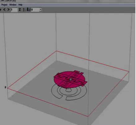
Meta Material based Micro strip patch antenna is designed using Sonnet Lite Simulator is shown in the figure
(1).
1. Desired frequency = 6 GHz
2. Substrate dielectric = 2.2 ( Rogers 5880)
3. Height of Substrate = 1.56 mm
4. Thickness of Conductor = 0.0023 µm.
There are four essential parameters for design of a Meta material based Microstrip Patch Antenna. The desired
frequency ( fo ) of the antenna must be selected appropriately. The frequency range used is from 5.5GHz to
6.5GHz and the design antenna must be able to operate within this frequency range. The desired
frequency selected for this design is 6 GHz. The dielectric material of the substrate (εr ) selected for this
design is ROGERS-5880 which has a dielectric constant of 2.2 and loss tangent equal to 0.001. The
dielectric constant of the substrate material is an important design parameter. Low dielectric constant is
used in the prototype design, because it gives better efficiency and higher bandwidth, and lower quality
factor Q. The low value of dielectric constant increases the fringing field at the patch periphery and
thus increases the radiated power. The proposed design has patch size independent of dielectric constant. So
the way of reduction of patch size is by using higher dielectric constant and ISOLA-IS640 is good in
this regard. The small loss tangent was neglected in the simulation. Height of dielectric substrate (h): For the
micro strip patch antenna to be used in cellular phones, it is essential that the antenna is not bulky. Hence, the
height of the dielectric substrate is selected as 1.56 mm.
III. SIMULATED RESULTS OF MICROSTRIP PATCH ANTENNA
The software used to model and simulate the microstrip patch antenna is Sonnet Lite software. Sonnet Lite is a
full-wave electromagnetic simulator. It analyzes 3D and multilayer structures of general shapes. An evaluation
version of the software was used to obtain the results for this thesis.
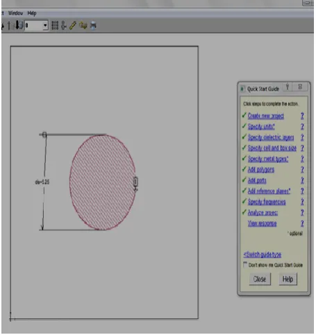
The Microstrip antenna consist of a planar resonant radiating element parallel to, but separated, from a ground
plane by a
thin dielectric substrate (t << ) was designed and simulated on Sonnet lite software. The Rogers5880 substrate
of The Microstrip antenna consist of a planar resonant radiating element parallel to, but separated, from a
ground plane by a dielectric 2.2 was used with height 1.56 mm. The input impedance of patch Rin is used to
calculate the 50 Ohm input impedance location of the patch where the feed line has to be connected. Fig. 2
shows the simulated single patch microstrip antenna with Microstrip line feed. The actual radiating element is
the large rectangle and the smaller rectangular section is a feed line. The impedance matching is necessary in
Fig 1: Meta Material Based Micro Strip Patch Antenna Designed Using Sonnet Lite Simulator
Fig.3: S-parameter Plot for Return Loss v/s Frequency for Meta Material Based Micro Strip
Antenna
Fig.5: S-Parameter Phase in Degrees
The above figure .5 represents the phase response of micro strip Patch Antenna at 6 GHz .Here the phase is
around 120.31 degree.
Now for the elevation pattern the antenna shall be simulated only at 6GHz, which is the operating frequency for
this design of the patch antenna. Here we have a few different specifications than for the S-Parameters, as
frequency at 6GHz.
IV. RESULTS AND DISCUSSION
There is a 40 % reduction in size of an antenna when it is loaded with CSRR and SRR structure. This is a very
major task to reduce the size of an antenna upto 40% . At resonant frequency of 6 GHz, the return loss is -27.18
dB and directivity is 2.8 dBi for antenna with CSRR and SRR structure, but when it is loaded with K-shaped
AMC then, return loss is -27.71 dB and directivity is 2.38. The radiation characteristics and impedance
characteristics for antenna are shown in Table 1.
Table 1. Impedance Characteristic and Radiation Characteristic for Antenna with K-Shaped
AMCS and with CSRR & SRR Structure
Parameter Patch Antenna With K-shaped AMC With CSRR & SRR
Band operation(GHz) 2.379-2.436 5.5-6.5 Return loss(S11)(dB) -27.71 -27.18 Impedance Bandwidth(%) 2.38 2.87
Antenna Size improvement (%) 10% 40% Antenna Directivity improvement 1.5dBi 2.8dBi Antenna Efficiency improvement (%) 8% 17%
REFERENCES
[1] M. S. Darak, S. Anand, and D. Sriram Kumar , “Bandwidth Enhancement of a Patch Antenna by Loading
Complementary K-shaped Artificial Magnetic Conductors in Ground Plane” Applied Electromagnetics
(APACE), pp. 224-227, Dec. 2014.
[2] S. Anand, D. Sriram Kumar, R. J. Wu, and M. Chavali, “Analysis and design of optically transparent
antenna on photonic band gap structures,”Optik, vol. 125, no. 12,pp. 2835-2839, 2014.
[3] K. Agarwal, Y. X. Guo, and A. Alphones, "Dual-band circularly polarized stacked microstrip antenna over RIS for GPS applications," In Wireless Symposium (IWS), 2013 IEEE International, pp. 1-4. IEEE, 2013.
[4] A. Lai C . Caloz, and T. Itoh, “Composite right/left- handed transmission line materials,” IEEE Microw Mag, vol.5, no. 3, pp. 34-50,Sep.2004.
[5] C. Caloz and T. Itoh, “Transmission line approach of left – handed(LH) materials & microstrip
implementation of an artificial LH transmission line,” IEEE Trans. Antenna Propag., vol.52, no. 5, pp.
1159-1166, May 2004.
[6] E. F. Knott , J.F. Shaeffer , and M.T. Tuley, Radar cross section , 2nd ed.; Scitech Publishing, 2004.
[7] A. Sanada , C. Caloz, and T. Itoh, “Characteristics of the composite right/ left- handed transmission lins,”
[8] A Lai, K. M. K. H. Leong, and T. Itoh , “ Dual – mode compact microstrip antenna based on fundamental
backward wave.” In Proc. Asia – Pacificx microw. Conf., Suzhov, China, dec. 2005, pp. 1- 4.
[9] D. Sievenpiper, L. Zhang, R. F. J. Broas, N. G. Alexopolous, and E. Yablonovitch, “High-impedance electromagnetic surfaces with a forbidden frequency band,” IEEE Trans. Microw. Theory Tech., vol. 47, no.
11, pp. 2059–2074, Nov. 1999.
[10] F. Yang and Y. Rahmat-Samii, “Reflection phase characteristics of the EBG ground plane for low profile wire antennas,” IEEE Trans. Antennas Propag., vol. 51, no. 10, pp. 2691–2703, Oct. 2003.
[11] D. Nashaat, H. A. Elsadek, E. A. Abdallah,M. F. Iskander, and H. M. EI Hennawy, “Ultrawide bandwidth 2 2 microstrip patch array antenna using electromagnetic band-gap structure (EBG),” IEEE Trans. Antennas
Propag., vol. 59, no. 5, pp. 1528–1534, May 2011.
[12]D. F. Seivenpiper, “High-impedance electromagnetic surfaces,” Ph.D. dissertation, Dept. Elect. Eng., Univ.
of California, Los Angeles, 1999.
[13] A. P. Feresidis, G. Goussetis, S.Wang, and J. C. Vardaxoglou, “Artificial magnetic conductor surfaces and their application to low profile high gain planar antennas,” IEEE Trans. Antennas Propag., Special Issue on
AMC, Soft Hard Surfaces and Other Complex Surfaces, vol. 53, no. 1, pp. 209–215, Jan. 2005.
[14]M. S. Darak, S. Anand, and D. Sriram Kumar, “Analysis and design of a K-shaped electromagnetic metamaterial structure,” In Light And Its Interactions With Matter, vol. 1620, no. 1, 2014 AIP publishing,
pp. 289-294. AIP, 2014.
[15]J. D. Kraus and R. J. Marhefka. Antenas for applications Mcgraw Hill, third edition, 2002.
[16] H. Nakano, K. Kikkawa, Y. Iitsuka, and J. Yamauchi, “Equiangu larspiral antenna backed by a shallow cavity with absorbing strips,” Antennas and Propagation, IEEE Trasactions on, vol. 56, no. 8, pp.2742–
2747, 2008.
[17] K. Louertani and T.-H. Chio, “Wideband and low-profile unidirectional spiral antenna with Meta-Material absorber,” in Antennas and Propagation Society International Symposium (APSURSI), 2013 IEEE, july
2013.