Conceptual Design of the ITER ECE Diagnostic – An Update
M. E. Austin1, H. K. B. Pandya2, J. Beno3, A. D. Bryant3, S. Danani2, R. F. Ellis4, R. Feder5, A. E. Hubbard6, S. Kumar2, A. Ouroua3, P. E. Phillips1, and W. L. Rowan1
1Institute for Fusion Studies, University of Texas, Austin, TX, USA
2ITER-India/Institute for Plasma Research, Bhat 382428, Gandhinagar, India 3Center for Electromechanics, University of Texas, Austin, TX, USA
4Inst. for Res. in Elec. and Applied Physics, University of Maryland, College Park, MD, USA 5Princeton Plasma Physics Laboratory, Princeton, NJ, USA
6Plasma Science and Fusion Center, Massachusetts Institute of Technology, Cambridge, MA, USA
Abstract. The ITER ECE diagnostic has recently been through a conceptual design review for the entire system including front end optics, transmission line, and back-end instruments. The basic design of two viewing lines, each with a single ellipsoidal mirror focussing into the plasma near the midplane of the typical operating scenarios is agreed upon. The location and design of the hot calibration source and the design of the shutter that directs its radiation to the transmission line are issues that need further investigation. In light of recent measurements and discussion, the design of the broad-band transmission line is being revisited and new options contemplated. For the instruments, current systems for millimeter wave radiometers and broad-band spectrometers will be adequate for ITER, but the option for employing new state-of-the-art techniques will be left open.
1 Introduction
The electron cyclotron emission (ECE) diagnostic on ITER will provide crucial measurements of electron temperature (Te), its fluctuation amplitude (δTe) for various MHD modes, as well as provide information on non-thermal electrons and the cyclotron power loss for the expected high temperature plasmas. In December 2011 a conceptual design review of the ITER ECE diagnostic was completed. The current plans for the front-end optics, waveguide transmission line, and back end instruments were presented. A number of issues were identified, some that will require further research and development to resolve. Here we present a few highlights of the design and some details of the problems that have been encountered.
2 Port plug layout
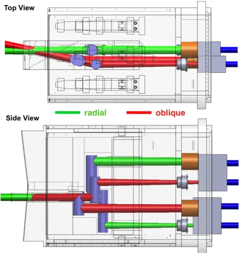
The layout of the ECE optics in the port plug has been through several iterations since the start of the conceptual design work. Fig. 1 shows the current configuration, with the components positioned in a vertical drawer. As in the original design there are two views, primarily for redundancy, but also one of the views is slightly oblique to be able to get additional information in the case of a non-Maxwellian electron distribution in ITER plasmas [1].
/
C
Owned by the authors, published by EDP Sciences, 2012
/
A major change in the port plug from earlier designs is the location of the calibration source. It was determined that in its original position in front of the first mirror that the source would be unlikely to survive for very long and then would be very difficult to repair or change out. Hence the source was relocated to the back of the port plug where it can be accessed via a special flange. However, there is a potential problem with this location due to the distance between the source and the first mirror and the additional optical bends involved. To properly function as a black body for calibration, the source must fill the view of the front end optics; with the larger distances, that may not be true for the longer wavelengths. A simple Gaussian beam analysis shows that the minimum mirror angle error fulfill the “3w” at the source opening is 0.15 degrees for 115 GHz. It is unlikely that this tolerance can be met. However, if the tube walls are sufficiently reflective, it may not matter if the radiation “bounces around”. This is something that should be tested in the laboratory.
Fig. 1. Layout of the ECE optics in ITER Port Plug 9 showing the top and sideways views. The plasma facing side is to the left. Both the radial and oblique views are shown along with the paths connecting
the front-end mirrors to the calibration sources (orange cylinders on the right).
An additional concern for the port plug optics is the mirror/shutter that rotates in front of the first mirror to couple in the calibration source. A design has been proposed employing special hinges that have never been used on a current fusion device hence some sort of real-world testing would be highly desirable.
3 Transmission line
One of the prime candidates for such a transmission line that has been used successfully for the ECE systems on a number of current fusion plasma devices is corrugated waveguide [2]. This waveguide has regular periodic grooves in the wall that produce a high surface reactance and thus low loss. It is constructed from metal tubing, typically aluminum, hence is rigidly strong and generally has good stability over the frequencies it is designed for. Due to the periodic deformations in the wall, this waveguide is susceptible to Bragg scattering which occurs when the half wavelength of the radiation approaches a corrugation period. However, for the lowest order propagating mode, the HE11 mode, it was expected that Bragg scattering would only produce large losses only over a few narrow bands at and above the Bragg frequency [3].
On the DIII-D tokamak, the Michelson interferometer ECE diagnostic has employed a corrugated waveguide transmission line since 1993 with stable low loss that permits good calibration of the instrument [4]. This transmission system has characteristics similar to one that was envisioned for ITER: a waveguide diameter of 63.5 mm, a narrow corrugation period of 0.38 mm with a depth of 0.25 mm, and a modestly long waveguide run containing several miter bends (15 m with 7 bends). For DIII-D ECE measurements only the range 70-300 GHz is used. However, since the Michelson interferometer is capable of measurements up to 1000 GHz, covering the ITER range, the opportunity was taken to test the broad-band attenuation of this line. This task was completed as part of a collaborative effort between the India and US ITER groups.
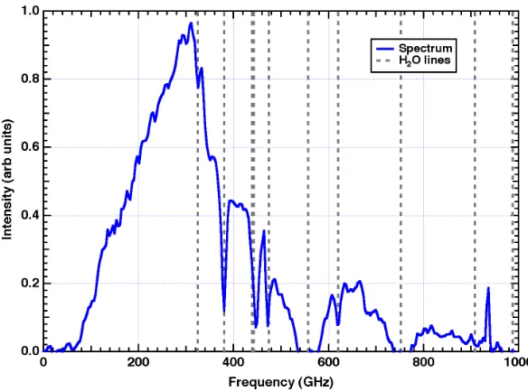
The millimeter wave source for these tests was a liquid nitrogen (LN2) blackbody source. To measure the transmission line loss the source was placed at the end of the line near the tokamak and directly in front of the Michelson instrument. A spectrum from a coherently averaged set of 10,000 scans was recorded for each location and the difference spectrum was calculated to get the total attenuation of the transmission line. A typical spectrum for the front end measurement is shown in Fig. 2. One problem for this test was the absorption of microwaves by water vapor since the DIII D line is operated in air. Above 300 GHz there are several lines, shown in the figure, that strongly attenuate the signal. However there are frequency windows not affected by these lines, around 600-700 GHz and 800-900 GHz for example, that still allow a measurement up to high frequency. One set of measurements was done with a partial nitrogen purge of the line which helped reduce the water absorption.
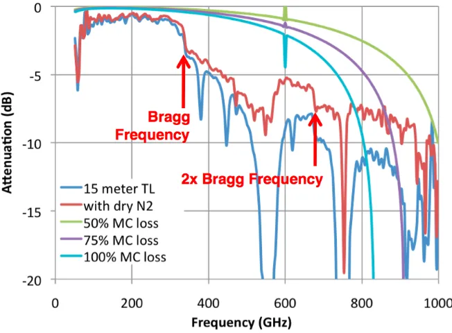
Fig. 3 shows the difference spectrum for the total transmission line of total length 15.4 m containing seven miter bends, for the measurements with and without the nitrogen purge. Immediately apparent is the sharp drop in transmission at the Bragg frequency and continuing up to the maximum frequency. As noted the water lines hamper the measurement over some frequency ranges but the overall trend is visible and a loss of roughly 8 dB is observed near 1000 GHz. Shown also in the figure are theoretical losses due to mode conversion for several assumed levels. It is clear that this type of loss does not fit the observed transmission; the losses exceed that expected for even 100% mode conversion and the trend is wrong. For a well aligned transmission line with precision miter bends one would expect mode conversion losses well below 50%.
These results have led the ITER ECE group to consider other type of transmission lines, including dielectric waveguide which has similar properties as corrugated waveguide but without the effects of Bragg scattering. The tests underscore the importance of measuring diagnostic components over the expected range of their use before committing to use them on ITER. Many current diagnostics will be used outside of their “standard” operating range, and their viability needs to be confirmed with experimental measurements.
Fig. 1. Measured attenuation of DIII-D transmission line with and without dry nitrogen purge and compared with theoretical losses due to mode conversion. A sharp increase in attenuation is seen near
the Bragg frequency.
4 Back-end instruments
The heterodyne radiometers are expected to be of the usual type, at least for the first harmonic range of frequencies, nominally 100-170 GHz. For the second harmonic, covering 200-300 GHz, the standard fundamental local oscillator/mixer setup will be impractical. Instead receivers will use DROs, multipliers, and subharmonically pumped mixers. In fact, a US company has recently completed a Department of Energy innovative research initiative and developed a such a receiver for use on the C-MOD tokamak, which requires a radiometer in the same ITER range. Hence, the heterodyne instrumentation for ITER is considered to be well in hand.
For the broad band multiharmonic measurement, the standard reciprocating Michelson interferometer is the current proposed instrument. It has the high throughput required for calibration and a proven history of success on tokamaks. However, its long dead-time intervals are a undesirable aspect and an improved option would be welcome. Being considered are a rotating Michelson with improved throughput and a possible Mach-Zehnder configuration that is being developed in the astronomy community. It is likely that one of these will prove viable for use in the years before ITER begins to run, but complete testing will be needed to verify.
5 Conclusions
Several design iterations for the ITER ECE system. have been completed in the years since planning started A number of early ideas have been shown to be unworkable, either through modelling or testing. The requirements for ITER-ECE are stringent and it will be necessary for the instruments to work under harsher conditions but with higher reliability than on current machines. What the experience up to now has shown is that it is critical to fully vet the various parts, front-end, transmission line, and back-end instruments, before they are committed for use on ITER.
References
1. G. Taylor and R. W. Harvey, Fus. Sci. Tech. 55, 64 (2009) 2. P. J. B. Clarricoats et al., Proc. IEE 122, 1173 (1975) 3. J. L. Doane, Fus. Sci. Tech. 53, 160 (2006)