Design & Implementation of a Universal
Communications Processor for Substation
Integration, Automation and Protection
Cagil Ramadan Ozansoy
SUBMITTED IN FULFILMENT OF THE REQUIREMENTS FOR THE DEGREE OF
DOCTOR OF PHILOSOPY
School of Electrical Engineering
Faculty of Health, Engineering and Science
Victoria University
I would like to dedicate this thesis to my wonderful
Declaration of Originality
Declaration of Originality
I, Cagil Ramadan Ozansoy, declare that the PhD thesis entitled “Design & Implementation of a Universal Communications Processor for Substation Integration, Automation and Protection” is no more than 100,000 words in length, exclusive of tables, figures, appendices and references. This thesis contains no material that has been submitted previously, in whole or in part, for the award of any other academic degree or diploma. Except where otherwise indicated, this thesis is my own work.
Contents
Contents
List of Figures ... v
List of Tables... x
List of Abbreviations ... xii
Acknowledgements ... xvii
Abstract ... xviii
List of Publications ... xxi
Chapter 1 Thesis Overview... 1
1.1 Introduction ...1
1.2 Aim of This Research...4
1.3 Research Methodologies and Techniques...6
1.4 Originality of the Thesis ...9
1.5 Organisation of the Thesis...10
Chapter 2 Literature Review ... 12
2.1 Introduction ...12
Contents
2.3 Automation, Integration and Communications...14
2.4 Protocols...17
2.4.1 The Ethernet Protocol ...18
2.4.2 The TCP/IP Internet Protocol Suite ...19
2.4.3 Protocols in Substations...20
2.5 Standardisation Developments ...21
2.5.1 The UCA Substation Communications Project...22
2.5.2 IEC 61850 Project...24
2.6 Middleware Architectures...26
2.6.1 Client/Server Architectures...28
2.6.2 Publish/Subscribe Architectures ...28
2.6.3 Popular Middleware Platforms ...30
2.7 Conclusion...35
Chapter 3 IEC 61850 Application View ... 37
3.1 Introduction ...37
3.2 Substation Automation Systems ...38
3.3 IEC 61850 Application View ...40
3.3.1 Logical Nodes ...41
3.3.2 Data...50
3.3.3 Data Sets ...62
3.3.4 Reporting and logging...67
3.4 Conclusion...85
Chapter 4 IEC 61850 Device View ... 86
4.1 Introduction ...86
4.2 IEC 61850 Device View...87
4.2.1 Logical Devices ...87
4.2.2 Server...91
4.2.3 The Generic Substation Event...94
4.2.4 The Transmission of Sampled Values...103
4.2.5 The Setting Group Control Block Model...110
Contents
Chapter 5
Communication Processor Design ... 119
5.1 Introduction ...119
5.2 IEC 61850 Communication View ...120
5.3 The Proposed Model...123
5.3.1 The Client/Server Communication Model ...125
5.3.2 The Publish/Subscribe Communication Model...126
5.4 The Design and Implementation of the IEC-MOM middleware ...134
5.4.1 IEC-MOM Architectural Overview ...134
5.4.2 IEC-MOM Implementation...138
5.5 The Design and Implementation of the Application Layer Modules...143
5.5.1 Server Application Layer Design and Implementation...143
5.5.2 Client Application Layer Design and Implementation...152
5.6 Performance Analysis of the System...155
5.6.1 The Bay Devices and Station Controller Simulation ...155
5.6.2 The GOOSE Demo Simulation...165
5.6.3 The Sampled Values Simulation...171
5.7 Conclusion...176
Chapter 6 Substation Time Synchronisation ... 178
6.1 Introduction ...178
6.2 Network Time Synchronisation...179
6.3 Simple Network Time Protocol ...182
6.3.1 SNTP Operation Modes...182
6.3.2 SNTP Implementation ...185
6.3.3 SNTP Filtering...186
6.4 Implementation of SNTP client and server applications...188
6.4.1 Application Layer Process Modelling of a SNTP Client ...189
6.4.2 Application Layer Process Modelling of a SNTP Server...192
6.4.3 Time Stamping...193
6.5 Performance Evaluation of the SNTP Protocol...196
6.5.1 No load case...197
6.5.2 5% load case ...199
Contents
Chapter 7
Hardware in the Loop Modelling & Simulation... 204
7.1 Introduction ...204
7.2 Hardware in the Loop Capability...205
7.3 Design and Implementation of the HITL Model ...206
7.3.1 The Client Gateway Design and Implementation ...207
7.3.2 The Server Gateway Design ...209
7.4 Hardware in the Loop Simulation ...212
7.5 Conclusions ...214
Chapter 8 Conclusions and Future Developments ... 215
8.1 Introduction ...215
8.2 Summary ...217
8.3 Future Work...220
References ... 223
Appendix A C++ Class Definitions of the Implemented Class Models ... 239
Appendix B Descriptions of Input and Output Parameters of Services ... 242
List of Figures
List of Figures
Figure 2.1 Digital relay with target interfaces [16] ... 13
Figure 2.2 Typical integrated substation protection and control system [23] ... 15
Figure 2.3 The OSI reference model ... 17
Figure 2.4 The Ethernet network concept [34]... 18
Figure 2.5 TCP/IP protocols and functional layers [26]... 19
Figure 2.6 The merging process [43]... 22
Figure 2.7 Three levels of UCA [44]... 23
Figure 2.8 The basic reference model [27]... 25
Figure 2.9 Relationship between the application and communication interfaces [27]... 26
Figure 2.10 Protocol stack incorporating the middleware layer... 27
Figure 2.11 A client/server communication model ... 28
Figure 2.12 Publish/subscribe communication model... 29
Figure 2.13 Basic CORBA Architecture [63] ... 31
Figure 2.14 The VMD Architecture [71] ... 33
Figure 3.1 An example of an application-view interoperable function... 40
Figure 3.2 Virtualisation... 41
Figure 3.3 A simple protection and measurement example ... 42
Figure 3.4 LN class diagram ... 43
Figure 3.5 Conceptual class models showing the LN and LLNO classes and their attributes ... 44
Figure 3.6 LN and LLNO class definitions ... 45
Figure 3.7 Flowchart diagram of the GetLogicalNodeDirectory service... 48
Figure 3.8 Flowchart diagram of the GetAllDataValues service ... 49
Figure 3.9 Data Classes of the XCBR LN... 50
Figure 3.10 Services operating on data ... 51
List of Figures
Figure 3.12 Data class diagram ... 53
Figure 3.13 CommonData class diagram ... 53
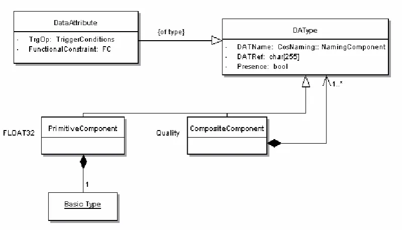
Figure 3.14 DAType conceptual class model... 55
Figure 3.15 Nested DataAttributes ... 55
Figure 3.16 FCDAType conceptual class model... 56
Figure 3.17 Example of a data instance... 57
Figure 3.18 Flowchart diagram of the GetDataDirectory service ... 58
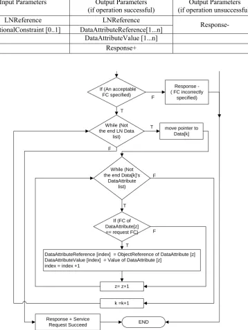
Figure 3.20 Continued flowchart diagram of the GetDataValues service... 61
Figure 3.21 DataSet members ... 63
Figure 3.22 DataSet class diagram ... 63
Figure 3.23 Flowchart diagram of the CreateDataSet service... 64
Figure 3.24 Flowchart diagram of the DeleteDataSet service... 65
Figure 3.25 Flowchart diagram of the SetDataSetValues service ... 66
Figure 3.26 Reporting and logging model... 67
Figure 3.27 BRCB class diagram ... 70
Figure 3.28 Flowchart diagram of the SetBRCBValues service ... 71
Figure 3.29 Report format ... 73
Figure 3.30 DataSet members and reporting... 75
Figure 3.31 Event_Monitor_Reporting service... 76
Figure 3.32 Report_Handler service... 77
Figure 3.33 LCB class diagram ... 79
Figure 3.34 Log class diagram ... 81
Figure 3.35 Flowchart diagram of the Log_Handler service... 84
Figure 4.1 Server conceptual model ... 88
Figure 4.2 Logical device building blocks ... 89
Figure 4.3 LD class diagram ... 89
Figure 4.4 Flowchart diagram of the GetLogicalDeviceDirectory service ... 90
Figure 4.5 Server building blocks... 91
Figure 4.6 Server class diagram ... 92
Figure 4.7 Flowchart diagram of the GetServerDirectory Service... 93
Figure 4.8 GOOSE model ... 95
List of Figures
Figure 4.10 Flowchart diagram of the SetGoCBValues service ... 97
Figure 4.11 Flowchart diagram of the GetGoCBValues service... 98
Figure 4.12 Flowchart diagram of the GetGoReference service ... 99
Figure 4.13 Flowchart diagram of the GetGOOSEElementNumber service ... 101
Figure 4.14 GOOSE message definition ... 101
Figure 4.15 SV Model ... 104
Figure 4.16 MSVCB class diagram... 105
Figure 4.17 SV message format ... 107
Figure 4.18 Flowchart diagram of the MSV_Handler service ... 109
Figure 4.19 Basic model of the SGCB ... 110
Figure 4.20 SGCB class diagram ... 112
Figure 4.21 Flowchart diagram the SelectActiveSG service... 113
Figure 4.22 Flowchart diagram of the SetSGValues service... 114
Figure 4.23 Flowchart diagram of the ConfirmEditSGValues service ... 115
Figure 4.24 Flowchart diagram of the GetSGValues service... 117
Figure 5.1 IEC 61850 communication models [84] ... 120
Figure 5.2 IEC 61850 communication profiles [11] ... 121
Figure 5.3 The overall communication processor architecture ... 123
Figure 5.4 Interaction between a client and a server ... 125
Figure 5.5 Multicast transmission ... 127
Figure 5.6 Feeder IED publishing to the subscribing IED [82]... 129
Figure 5.7 Priority queuing [118] ... 131
Figure 5.8 IEC-MOM architecture ... 134
Figure 5.9 Communication processor node model... 139
Figure 5.10 Process model of the IEC-MOM middleware module... 140
Figure 5.11 IEC-MOM child process model ... 142
Figure 5.12 Architectural components of the ACSI server application layer module . 147 Figure 5.13 ACSI server application layer module process model ... 150
Figure 5.14 ACSI client application layer module process model ... 153
Figure 5.15 BDASC simulation test set-up ... 155
Figure 5.16 Nested structure of the Circuit_Breaker... 156
List of Figures
Figure 5.18 BDASC simulation console output ... 161
Figure 5.19 Amount of traffic (bits/sec) received at the... 163
SUC and Circuit_Breaker... 163
Figure 5.20 Application-to-application delays of packets received at the SUC and Circuit_Breaker ... 164
Figure 5.21 GOOSE demo simulation test set-up ... 166
Figure 5.22 Nested structure of the Protection_Relay... 167
Figure 5.23 Nested structure of the AutoRecloser_Relay ... 167
Figure 5.24 Nested structure of the Switchgear_Relay ... 167
Figure 5.25 GOOSE Demo simulation console output ... 168
Figure 5.26 Amount of traffic received at the Switchgear_Relay... 169
Figure 5.27 Application-to-application delays of GOOSE messages received at the Switchgear_Relay... 170
Figure 5.28 Sampled Values simulation test set-up ... 172
Figure 5.29 Sampled Values simulation console output ... 173
Figure 5.30 SV traffic throughput (bits/sec) and the amount of GOOSE traffic received at the Protection_Relay ... 174
Figure 5.31 Application-to-application delays of GOOSE and SV messages received at the Protection_Relay... 175
Figure 6.1 The basic TS process... 179
Figure 6.2 IEC 61850 TS model... 180
Figure 6.3 SNTP message format... 183
Figure 6.4 ACSI server node Figure 6.5 SNTP TimeServer node ... 189
Figure 6.6 Application layer process model of an IEC 61850 server node... 190
Figure 6.7 Flowchart description of the ss_packet_destroy_sntp function ... 191
Figure 6.8 Application layer process model of an SNTP server node ... 192
Figure 6.9 MAC layer STD ... 196
Figure 6.10 Multilevel test set-up... 197
Figure 6.11 Sent and received SNTP traffic... 198
Figure 6.12 Round trip delay and local offset calculated in the Protection_Relay ... 198
Figure 6.13 Round trip delay and local offset calculated for the 5 % load case ... 200
List of Figures
Figure 6.15 Filtered and un-filtered local offset values... 202
Figure 7.1 Simulations linked through a real network ... 205
Figure 7.2 Client gateway node model... 207
Figure 7.3 STD of the “Client Network Interface” module ... 208
Figure 7.4 Flowchart diagram of the client’s sending process... 209
Figure 7.5 Flowchart diagram of the client’s receiving process... 209
Figure 7.6 Server gateway node model ... 210
Figure 7.7 STD of the “Server Network Interface” module... 210
Figure 7.8 Flowchart diagram of the server’s receiving process... 211
Figure 7.9 Flowchart diagram of the server’s sending process ... 211
Figure 7.10 HITL simulation test set-up ... 212
Figure 7.11 Simulation console output of D704-5 computer ... 213
List of Tables
List of Tables
Table 3.1 ObjectNames of LNs and LDs ... 46
Table 3.2 Parameters of the GetLogicalNodeDirectory service... 47
Table 3.3 Parameters of the GetAllDataValues of the service ... 49
Table 3.4 Parameters of the GetDataDirectory service ... 57
Table 3.5 Parameters of the GetDataDefinition service ... 59
Table 3.6 Parameters of the GetDataValues service ... 59
Table 3.7 Parameters of the SetDataValues service ... 62
Table 3.8 Parameters of the CreateDataSet service... 64
Table 3.9 Parameters of the DeleteDataSet service... 65
Table 3.10 Parameters of the SetDataSetValues service... 65
Table 3.11 Parameters of the GetDataSetValues service ... 66
Table 3.12 Parameters of the GetDataSetDirectory service ... 67
Table 3.13 Parameters of the SetBRCBValues service... 71
Table 3.14 Parameters of the GetBRCBValues service ... 72
Table 3.15 Parameters of the SetLCBValues service... 80
Table 3.16 Parameters of the GetLCBValues service ... 80
Table 3.17 Parameters of the QueryLogByTime service ... 81
Table 3.18 Parameters of the QueryLogAfter service... 82
Table 3.19 Parameters of the GetLogStatusValues service... 82
Table 4.1 Parameters of the GetLogicalDeviceDirectory service ... 90
Table 4.2 Parameters of the GetServerDirectory service ... 93
Table 4.3 Parameters of the SetGoCBValues service ... 97
Table 4.4 Parameters of the GetGoCBValues service... 98
Table 4.5 Parameters of the GetGoReference service... 99
List of Tables
Table 4.7 Parameters of the SetMSVCBValues service... 106
Table 4.8 Parameters of the GetMSVCBValues service... 106
Table 4.9 Parameters of the SelectActiveSG service ... 112
Table 4.10 Parameters of the SelectEditSG service ... 113
Table 4.11 Parameters of the SetSGValues service ... 114
Table 4.12 Parameters of the ConfrimEditSGValues service ... 115
Table 4.13 Parameters of the GetSGCBValues service ... 116
Table 4.14 Parameters of the GetSGValues service... 116
Table 6.1 IEC Classes T1-T5 ... 181
Table B.1 Input parameters ... 242
List of Abbreviations
List of Abbreviations
ACSI Abstract Communication Service Interface ALP Application Layer Protocol
API Application Programming Interface BDASC Bay Devices and Station Controller
BRCB Buffered Report Control Block CASM Common Application Service Models
CDC Common Data Classes
CmpCmp Composite Components
CompositeCDC Composite Common Data Class
CORBA Common Object Request Broker Architecture COTS Commercial off-the Shelf
CPU Central Processing Unit
CSMA/CD Carrier Sense Multiple Access/Collision Detection
CSWI Switch Controller
CT Current Transformer
DII Dynamic Invocation Interface
DLN Domain Logical Node
List of Abbreviations
EPRI Electric Power Research Institute
FC Functional Constraint
FCDA Functionally Constraint Data Attribute FCDATypes Functionally Constraint Data Attribute Types
FIFO First-In First-Out
FPGA Field Programmable Gate Array
FSM Finite State Machine
GIOP General Inter-ORB Protocol
GoCB GOOSE Control Block
GOMSFE Generic Object Models for Substation and Feeder Equipment GOOSE Generic Object Oriented Substation Event
GPS Global Positioning System
GsCB GSSE Control Block
GSSE Generic Substation State Event HITL Hardware in the LOOP
HMI Human Machine Interface
HTTP HyperText Transfer Protocol I&C Instrumentation & Control IDL Interface Definition Language
IEC International Electrotechnical Commission IED Intelligent Electronic Device
IEEE Institute of Electrical and Electronics Engineers IGMP Internet Group Management Protocol
List of Abbreviations
IP Internet Protocol
ISO International Standards Organization
LAN Local Area Network
LCB Log Control Block
LCO Local Clock Offset
LD Logical Device
LLNO Logical Node Zero
LN Logical Node
LPHD Physical Device Logical Node
MAC Media Access Control
MFC Microsoft Foundation Class MltcMS Multicast Membership Service
MMS Manufacturing Message Specification
MOM Message-Oriented Middleware
MSVCB Multicast Sampled Value Control Block
MV Measured Value
NTP Network Time Protocol
NTS Network Time Synchronisation
OM Object Models
OMA Object Management Architecture
OO Object Oriented
OOM Object Oriented Modelling
OOP Object Oriented Programming
List of Abbreviations
ORB Object Request Broker
OSI Open Systems Interconnection
PC Personal Computer
PIOC Instantaneous Overcurrent Device
PH Physical Device
PPAM Phase Angle Relay
PrmCmp Primitive Components
QoS Quality-of-Service
RMI Remote Method Invocation
RSVP Resource Reservation Protocol
RTD Round Trip Delay
RTU Remote Terminal Unit
SA Substation Automation
SAS Substation Automation System SCADA Supervisory Control and Data Acquisition SCL Substation Configuration Description Language SCSM Specific Communication Service Mapping SEL Schweitzer Engineering Laboratories
SG Setting Group
SGCB Setting Group Control Block
SI Substation Integration
SimpleCDC Simple Common Data Class
SNTP Simple Network Time Protocol
List of Abbreviations
STD State Transition Diagram
SV Sampled Values
SVM Sampled Values Model
SUC Station Unit Controller
TC Technical Committee
TCP Transmission Control Protocol
TCTR Current Transformer
TOS Type of Service
TPAL Transport Protocol Application Layer
TrgOp Trigger Option
TS Time Synchronisation
UCA Utility Communication Architecture
UDP User Datagram Protocol
UML Unified Modelling Language
URCB Unbuffered Report Control Block
US United States
USDM Utility Standard Device Model USVCB Unicast Sampled Value Control Block UTC Coordinated Universal Time VMD Virtual Manufacturing Device
VT Voltage Transformer
WRED Weighted Random Early Detection
XCBR Circuit Breaker
Acknowledgements
Acknowledgements
First and foremost, I would like to express my special appreciation to my supervisors, A/Prof. Aladin Zayegh and Professor Akhtar Kalam, for their guidance, assistance and encouragement during this research. Their timely advice and support have greatly contributed to the completion of this thesis.
I also would like to thank my colleagues in the School of Electrical Engineering for their valuable support. In particular, I would like to thank Amanullah Maung Than OO, David Fitrio, Alexander Stojcevski, Ronny Veljanovski, Hai Phuong Le and other friends in room D706, School of Electrical Engineering. In addition, I would like to express my gratitude to the administrative officer Maria for all the assistance in relation to administrative matter. I also wish to appreciate the technical officer, Foster Hayward, and the computer systems officer, Abdulrahman Hadbah, for all their technical and software related assistance.
Above all, I would like to give special thanks to my aunty, Emel Huseyin, and my mother, Meral Ekmekci, for their love, patience, understanding and encouragement during this research.
Abstract
Abstract
Substation Automation (SA) is a rapidly increasing area of interest in Electrical Engineering these days embracing numerous benefits to utilities. It is clearly the most dynamic and exciting new development in the substation industry with the ultimate goal of efficiently managing operations, maintenance and capital assets with minimal human intervention [1-4]. Intelligent Electronic Devices (IEDs), which are Instrumentation & Control (I&C) devices built using microprocessors, are the most important elements of a SA system. An IED is primarily used as a monitoring, control, protection or data processing device with at least a single serial communication interface.
Abstract
developed by the IEC Technical Committee (TC) 57. It describes how devices are to communicate in a substation as well as the related system requirements. It features support for all substation functions and their engineering with the use of OO data and service models [5]. However, it has only been abstractly modelled meaning that it focuses on describing what the OO models are indented to provide rather than how they are built. Consequently, the IEC 61850 standard can only be operational when mapped to a specific concrete application layer protocol such as the Manufacturing Message Specification (MMS) or ISO/IEC 8802-3, which are the two communication services put forward by the IEC 61850 standard.
The primary objective of this research is the OO implementation of the IEC 61850 standard as a concrete application layer protocol running on a middleware platform designed and implemented in a communication processor environment. In this research, the IEC 61850 implementation is founded on the C/C++ programming language development of the standard’s Abstract Communication Service Interface (ACSI) Object and Service Models (OSMs) as concrete programs based on their published definitions, hence transforming the IEC 61850 standard into a solid protocol. An alternative to the present implementation practice, the mapping process as proposed in the IEC 61850 standard, is recommended where virtual representations of real devices can be modelled and implemented at the application layer of a communication processor making use of the OO implemented OSMs of the standard itself rather than using the equivalent models of another application layer protocol.
Abstract
a network. Middleware design is based on architectural issues concerned with the organisation, overall structure and communication patterns dictated by applications as well as the middleware itself [6-7]. This thesis describes the design and implementation of a new middleware architecture aimed at providing diverse communication methods to IEC 61850 related applications. The designed middleware is of the Message-Oriented Middleware (MOM) category and considers the fact that communicating entities may take on different roles such as client/server or peer-to-peer, therefore allowing for different interaction modes such as synchronous invocations and asynchronous message passing. Several simulation studies are also presented in this thesis to demonstrate how IEC 61850 applications can be built at the application layer of a communication processor as well as to test and evaluate the performance of the middleware architecture implemented within the same communication processor environment.
Chapter 1: Thesis Overview
Chapter 1
Thesis Overview
1.1 Introduction
Substation Automation (SA) is a supervisory management and control system for industrial electrical distribution systems. The interest on SA has been increasing rapidly due to its numerous benefits to utilities. It has advanced further than a traditional Supervisory Control and Data Acquisition (SCADA) system providing additional capability and information that can be used to further improve operations, maintenance and efficiencies in substations [8]. The most significant elements of a SA system include relays and/or Intelligent Electronic Devices (IEDs) that perform various control, monitoring and protection related operations.
Chapter 1: Thesis Overview
standardisation, both users and suppliers arrive at economically suitable and reliable solutions. For the last decade, there has been lot of work done on standardising the language of communication between IEDs and relays [9-10]. As a result, two main protocols have evolved: the existing Utility Communication Architecture (UCA) [9] and the new International Electrotechnical Commission (IEC) 61850 [10]. The latter is expected to dominate the communications in the substation environment in the near future.
Chapter 1: Thesis Overview
IEC 61850. GOOSE is a fast connection-less communication service used for the transfer of time-critical data where high speed and security are achieved by the repetition of messages a number of times.
One of the most significant architectural constructs of the IEC 61850 is the adoption of an “abstracting” technique, which involves the creation of objects that are independent of any underlying protocol. The isolation of the information models and information exchange services from the underlying on-the-wire protocols is usually seen as one of the most powerful capabilities of the IEC 61850 standard. The abstract nature of the definitions permits the mappings of the data objects and services to any other protocol, which provides adequate communication procedures meeting the data and service requirements of the IEC 61850 standard [11]. Currently, IEC 61850 only specifies mappings on a communication stack that includes the Manufacturing Message Specification (MMS) over the Transmission Control Protocol/Internet Protocol (TCP/IP) and Ethernet. However, the potential need to support mappings to different communication models has clearly been recognised in the industry and examples do exist in the literature detailing such mappings.
Chapter 1: Thesis Overview
1.2 Aim of This Research
The overall goal of this research is the OO implementation of the IEC 61850 standard as a concrete application layer protocol running above a middleware layer specifically designed and implemented in a real-time communication processor environment to support all the communication needs required by the standard. The term “communication processor” is referred to a device, which has a set of network protocol layers that work together in controlling the connection, communication and data transfer between two computing endpoints. In this research, the software based design and implementation of various layers of a communication processor protocol stack is described. The specific tasks to achieve a successful completion of this research are:
• Object-oriented implementation of the IEC 61850 standard: This task involves the OO implementation of the IEC 61850 Abstract Communication Service Interface (ACSI) Object and Service Models (OSMs) as concrete programs. The implementation of the ACSI OSMs based on their published definitions in the standard involves a two-stage procedure. First the OSMs that form the standard’s application-view constituent are implemented followed by those, which form the standard’s device-view constituent. The main aim is therefore the transformation of the IEC 61850 standard from an abstract nature into a solid protocol with the development of the smaller components forming the standard. Overall, a standard C/C++ language based implementation is proposed.
Chapter 1: Thesis Overview
modules as part of a communication processor protocol stack where IEC 61850 client and server applications can be modelled and configured. The software based design and implementation of two application layer modules is presented for this purpose, one where ACSI clients can be constructed and the other where ACSI servers can be constructed. The designed modules permit the use of the developed OSMs from the first task when constructing various representations of real devices at the application layer.
• Design and implementation of a data delivery network middleware: This task includes the design and implementation of a data delivery network middleware, the IEC-MOM, as a separate module between the application and network access layers of a communication processor. The designed Message-Oriented Middleware (MOM) architecture enables IEC 61850 processes running on different machines to interact over a network by providing various communication procedures for the transmission of IEC 61850 related messages. It supports all messages types specified by the IEC 61850 standard and incorporates various communication techniques such as unicast and multicast providing a unique stand-alone communication interface to the IEC 61850 processes running at the application layer of the same communication processor. It also considers stringent IEC 61850 specific Quality of Service (QoS) requirements such as the need of repeating GOOSE messages a number of times to achieve higher reliability and integrates solutions in its architecture for such requirements.
Chapter 1: Thesis Overview
the harmonisation of the local clocks of all communicating nodes within a network, is also crucial in time-sensitive substation applications. This task focuses on the implementation of a Commercial off-the Shelf (COTS) TS protocol, the Simple Network Time Protocol (SNTP), and its incorporation into ACSI applications. The SNTP is implemented making use of the Object Oriented Programming (OOP) techniques and SNTP client applications are integrated into the designed ACSI application layer modules. On the other hand, SNTP server applications are configured in stand-alone communication processors. The IEC-MOM middleware is also modified such that it provides support for the SNTP request/reply messages as well as the QoS requirements concerned with TS applications. An adaptive filtering technique and a lower-layer time stamping technique are proposed and demonstrated to be beneficial in meeting the TS accuracy requirements imposed by the IEC 61850 standard.
• Design and implementation of a “Hardware in the LOOP” (HITL) capability: The objective of this task is to develop a capability that will permit for the testing of the designed components over a real network. The proposed HITL capability acts as a gateway between the simulation environment and the real Ethernet network establishing a link between the virtual simulation and the real network and enabling message passing between the two.
1.3 Research Methodologies and Techniques
Chapter 1: Thesis Overview
that runs on exclusively designed middleware architecture. The design, implementation, simulation and testing of various components will be carried out using appropriate software development and network design tools. The details of proposed methodology and techniques to achieve the requirements of this research project are as follows:
(i) Literature review
To start with, the IEC 61850 standard is to be examined in detail as well as identifying the most appropriate software development technique to achieve the successful implementation of the standard. The communication requirements set by the IEC 61850 standard will be investigated and the currently available communication architectures will be analysed in order to recognise their strengths and weaknesses. Finally, the exact detailed specifications for the middleware architecture will be drawn.
(ii) Implementation of the IEC 61850 standard
Implementation of the IEC 61850 standard is at the core of this research. Several components of the standard need to be examined, assessed and implemented based on their OO definitions. The OO features of the C++ programming language, its popularity and widespread use in engineering applications make it the most suitable candidate for this task. Therefore, this task will be carried out using Microsoft Visual C++ 6.0, which is part of Microsoft’s software development suite, the Visual Studio.
(iii) Design and implementation of IEC 61850 application layer modules
Chapter 1: Thesis Overview
design package. Optimised Network Engineering Tools (OPNET) has been chosen for this purpose, which is an OO discrete-event network simulator allowing for the modelling, implementation, simulation and performance analysis of communication networks and distributed applications.
(iv) Design and implementation of the middleware architecture
The design and implementation of a data delivery network middleware architecture with respect to the identified design constraints needs to follow and will be carried out once more making use of the OPNET network simulation & design package. Once this task is concluded, the overall communication system will be tested with regards to the identified communication requirements to evaluate the performance of the designed architecture in terms of speed, reliability and efficiency.
(v) Implementation of the time synchronisation protocol
This task comprises a two-stage procedure. First, the software development of various components of the SNTP TS protocol needs to be accomplished followed by the incorporation of the developed components into the designed application layer modules where TS processes can be modelled and constructed. Once successfully completed, simulations will be carried out to test the overall design with respect to TS accuracy requirements.
(vi) Design and implementation of the HITL capability
Chapter 1: Thesis Overview
as converters between the virtual simulation environment and the real Ethernet network. Once completed, the overall design will be tested for a real network scenario involving the use of real Ethernet links, switches, routers, etc.
1.4 Originality of the Thesis
This research will contribute to the knowledge in substation communication system design since it tackles major issues related to standardisation efforts and establishment of open and standard working environments following the path initiated by the UCA 2.0. This research will contribute to knowledge in the following specific areas:
(1) Contributes to the knowledge by addressing a previously neglected area that is the transformation of the IEC 61850 standard into a solid application layer protocol with the development of concrete programs for the standard’s application and device-view OSMs. No other such OO implementation of the standard exists in the literature other than implementation through the mapping processes. The proposed research will be immensely beneficial to power protection and control engineers since it further enhances the understanding of the IEC 61850 standard and simplifies its use by illustrating how the OO models discussed in the standard can as well be implemented using the OOP techniques. This research is significant since it fully isolates the standard from the underlying protocols by providing a standard universal OO implementation removing the standard’s dependency on the mapping process.
Chapter 1: Thesis Overview
all sorts of communication mechanisms to IEC 61850 based applications running within substations. This research is significant since it proposes a middleware architecture that integrates all required message distribution mechanisms in its architecture eliminating the need for the multiple communication service mappings that exists as a burden in the existing IEC 61850 standard. The proposed middleware only provides a communication interface to IEC 61850 and does not include any object or service models.
(3) The proposed research is significant since it further integrates a TS protocol into the communication processor architecture, which makes it possible to harmonise the local clocks of all the communicating IEDs within a substation network relative to a chosen reference so that sensing and actuation of time-sensitive data can be coordinated accurately across multiple nodes.
(4) Contributes to knowledge by describing a preliminary work carried out to demonstrate how the software design can be interfaced to a real network.
1.5 Organisation of the Thesis
This thesis contains eight chapters and is organised as follows:
Chapter 1: Thesis Overview
technologies are discussed highlighting the importance of middleware in the strategy of establishing an open and standard working environment.
The development implications and implementation details of all application-view constituent components of the IEC 61850 standard are presented in Chapter 3. The typical building blocks of the IEC 61850 application view comprise logical nodes, data, data sets, etc., where logical nodes are the key elements comprising all other building blocks. In-dept study of the standard and the use of OOP techniques and methodologies in the implementation of various ACSI OSMs are presented. Chapter 4 looks at the modelling and implementation aspects of the standard’s device-view constituent components such as logical devices.
Chapter 5 presents the software based design and implementation of the various protocol layers of a communication processor stack including the application layer modules and the middleware architecture. The design and implementation details of these components are individually discussed. Performance analysis of the overall communication system will be considered to justify proper function of the designed components as well as the appropriateness of design techniques and methodologies.
Chapter 2: Literature Review
Chapter 2
Literature Review
2.1 Introduction
The purpose of this chapter is to provide the necessary background required to understand the concepts that relate to power system communications, recent standardisation developments and the use of protocols and middleware architectures in substations. When designing any type of middleware, it is important to learn from past research experience, which has resulted in many contrasting middleware technologies with different strengths and weaknesses [13]. The evolution of the recent standards such as UCA 2.0 and IEC 61850 will eventually lead to the replacement of various existing proprietary solutions with a standard communication approach for all future equipment from all around the world [14, 15]. The use of middleware technologies is fundamental to the strategy of establishing an open and standard working environment complementing the works of the standardisation developments.
Chapter 2: Literature Review
Section 2.5 discusses the recently developed application layer protocols. The chapter follows with Section 2.6, which reviews the state-of-the-art middleware architectures with special attention given to their use in power system communications.
2.2 Intelligent Electronic Devices
Many of today’s electric utility substations include digital relays and other Intelligent Electronic Devices (IEDs) that record and store a variety of data in relation to their control interface, internal operation and about the power system they monitor, control and protect. Instrumentation & Control (I&C) devices, which are built using microprocessors, are commonly referred to as IEDs. Microprocessors are single-chip computers that can process data, accept commands and communicate information. Nowadays, digital relays are widely replacing the aging electromechanical and solid-state electronic component-type relays and relay systems [16].
Figure 2.1 shows a digital relay with its target interfaces. Digital relay’s popularity comes from their low price, reliability, functionality and flexibility. However, the most important feature that separates a digital relay from previous devices is its capability of collecting and reacting to data and then using this data to create information. Such information includes [16, 17]:
Chapter 2: Literature Review
• Protection Data: Fault location and fault type,
• Metering Data: Pre-fault, fault and post-fault currents and voltages,
• Breaker and relay operation data, and
• Diagnostic and historical data [18].
IEDs can also run automatic processes while communications are handled through a serial port similar to the communication ports on a computer. Some examples of IEDs used in a power system are [19]:
• Instrument transformers,
• Remote Terminal Units (RTUs), and
• Digital fault recorders.
2.3 Automation, Integration and Communications
Power system automation is the act of automatically controlling the power system via I&C devices whereas Substation Automation (SA) refers to the use of IED data and control commands from remote users to control the power system devices within a substation. Power system integration, on the other hand, refers to communicating data to, from, or amongst IEDs in an I&C system. Finally, Substation Integration (SI) stands for combining IEDs’ local data in a substation so that there is a single point of contact in the substation for all of the I&C data [19, 20].
Chapter 2: Literature Review
UCA Gateway
Legacy IED
IED IED
Ethernet
Hub Router
Substation HMI
WAN
SCADAMaster
Laptop Computer
Data Concentrator
Terminal Server
Terminal Server Engineering
Station
RS 485
RS 485
RS 485 RS 485
Ethernet Ethernet
RS 232
RS 232
diagnose faults. When voltages and currents are analysed only from one terminal, it cannot be concluded whether a fault near the far end terminal is internal or external to the protected line segment. This requires delayed tripping for such faults, which can endanger system stability or increase vulnerability. At the far end terminal, the decision whether the fault is internal or external is obvious not from a distance measurement but from the knowledge of the direction of the fault. This information can be transmitted to the other terminal enabling it to decide whether to send signal to trip or not to trip [21].
Power utilities are focused on increasing productivity and making electric power safer, more reliable and economical by providing innovative, simple to use and robust technologies. Development of appropriate communication technologies and protocols is at the heart of this strategy. When relays and IEDs are integrated together, they form a powerful and economical I&C system capable of supporting all aspects of electric power protection, automation and control [22]. Figure 2.2 shows how IEDs and relays can be interconnected together forming protection schemes for power systems.
Chapter 2: Literature Review
The relaying and measurement tasks have been well understood and standardised. On the other hand, the technical methods and operating impact of data communications continue to evolve dramatically. There is a wide variety of incompatible communication approaches and systems in the marketplace. Competing manufacturers have been following unique approaches when designing their communication interface circuits. As a result, the users could not directly interconnect competing products and had to provide a different communication system for each vendor. However, the use of competing products from different vendors offers a variety of protection and monitoring capabilities for users although they are often frustrated by the communication related variations [15].
The desire and the need of merging the communication capabilities of all relays and IEDs in a substation has thus been clearly recognised, which is capable of providing not only data gathering and setting capability but also remote control. Furthermore, multiple IEDs can share data or control commands at higher speeds to perform new distributed protection and control functions [15]. Interoperability [24, 25] needs to be achieved in a substation between protective relays from different manufacturers so that substation level interlocking, protection and control functions can be realised improving the efficiency of microprocessor based relay applications [26].
Chapter 2: Literature Review
of existing standards and commonly accepted communication principles together with the new standards such as IEC 61850 and UCA provides a solid base for interoperability leading to more flexible and powerful protection and control systems [27].
2.4 Protocols
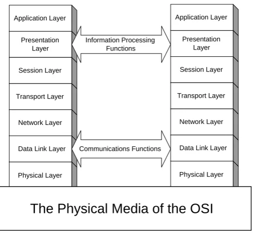
A protocol is basically a set of rules that must be obeyed for orderly communication between two or more communicating parties [28]. The International Standards Organisation (ISO) has divided the communication process into seven basic layers as shown in Figure 2.3, which is commonly referred to as the Open Systems Interconnection (OSI) model [28-30].
Figure 2.3 The OSI reference model
Each level operates independently of the others and has a certain function to perform. However, the successful operation of one level is mandatory for the successful operation of the next level. These layers define how data flows from one end of a
Application Layer Presentation
Layer Session Layer
Transport Layer
Network Layer
Data Link Layer
Physical Layer
Information Processing Functions
Communications Functions
Application Layer Presentation
Layer Session Layer
Transport Layer
Network Layer
Data Link Layer
Physical Layer
Chapter 2: Literature Review
communication network to another and vice versa. Two devices can only communicate if each layer in the model at the sending device matches with each layer in the model at the receiving device [29, 30]. Communication between data processing systems from different manufacturers has often been particularly difficult due to the fact that there has been separate development of data processing and data communication techniques, often resulting in complex and expensive interfaces.
2.4.1 The Ethernet Protocol
The Ethernet protocol [31, 32], a network concept illustrated in Figure 2.4, is one of the most widely used data link layer protocols designed for carrying blocks of data called frames as described by the IEEE 802.3 standard [33]. Ethernet uses an access method called Carrier Sense Multiple Access/Collision Detection (CSMA/CD) [33], which is a system where each host listens to the medium before transmitting any data to the network.
Figure 2.4 The Ethernet network concept [34]
Chapter 2: Literature Review
and wait a random amount of time before attempting to re-transmit. Although collisions affect the total throughput, the delay caused by the re-transmissions is very small normally not affecting the speed of transmissions on the network. Ethernet allows for the transmission of data from a speed of 10 Mbps to 1000 Mbps [35].
2.4.2 The TCP/IP Internet Protocol Suite
The Internet Protocol (IP) is a network layer protocol, which uses datagrams to communicate over a packet-switched network [36, 37]. It provides datagram services for transport layer protocols such as Transmission Control Protocol (TCP) and User Datagram Protocol (UDP). It is one of the subset protocols of the TCP/IP suite as illustrated in Figure 2.5.
Figure 2.5 TCP/IP protocols and functional layers [26]
The IP forms a computer network by connecting computers assigning each one a unique IP address [38]. Each IP packet carries an IP address [39], which consists of two parts: a destination address and a host address. The host address is the IP address of the sending computer, whereas the destination address is the address of the recipient or recipients of
OSI layers TCP/IP layers TCP/IP examples
Application Presentation
Physical Data Link
Network Transport
Session
Application
Transport
Internet
Network interface and
hardware
Telnet FTP SMTP DNS TFTP Telnet
TCP UDP
ARP RARP
IP
ICMP
Chapter 2: Literature Review
the packet. Routers, switches make use of the destination address when forwarding packets across interconnected networks.
The major concern with IP is that it makes no attempts to determine if packets reach their destination or to take corrective action if they do not. Therefore IP does not provide guaranteed delivery. This problem can be avoided in some applications where a transport protocol that carries out such a function is used. The best example for the latter is TCP [40], which makes up for IP's deficiencies by providing reliable, stream-oriented connections that hide most of IP's shortcomings. However, other applications requiring best effort services (faster transmission times) usually use UDP [41], which is a simple connection-less transport layer protocol without any real mechanisms for reliable delivery. UDP packets are delivered the same as the IP packets and may even be discarded before reaching their destinations.
Although the transmission of data requires the best-effort service in some substation applications, reliability is also a major concern. The best effort service requires the use of UDP, which has no support whatsoever for reliable transmission. This implies that certain primitives need to be implemented to achieve higher reliability in cases where IP is to be used alongside UDP. This is one of the major concerns being looked at in this research with a model being proposed in this thesis to solve this problem.
2.4.3 Protocols in Substations
Chapter 2: Literature Review
• MODBUS: A popular master-slave protocol with industrial users, which has become popular in substations. It issues simple READ/WRITE commands to addresses inside an IED.
• Distributed Network Protocol (DNP): An increasingly popular master-slave protocol mainly used in North America. DNP can run over multiple media, such as RS-232 and RS-485 and can issue multiple types of READ/WRITE messages to an IED.
• IEC-870-5-101: is considered as the European partner to DNP. It differentiates itself from DNP with its slightly different messaging structure and the ability to access object information from the IED.
2.5 Standardisation Developments
Chapter 2: Literature Review
aimed at creating a framework for not only common communication but also an architecture that will provide for interoperability. The ability to “plug and play” is referred to as interoperability, also meaning to be able to “share” data and functions [24].
UCA [9] was commissioned by the EPRI in 1994 to identify the requirements, overall structure and specific communication technologies to implement the standardisation scheme. The adopted approach defined the technical requirements for a system to control and monitor substations of any size [15]. The Technical Committee (TC) 57 of the IEC began work on IEC 61850 [10] in 1996 with a similar target. In 1997, the two groups joined together to define a common international standard that would combine the work of both groups. The result of the harmonisation process is the IEC 61850 standard, which is a superset of UCA 2.0 as shown in Figure 2.6 while offering some additional features [43].
Figure 2.6 The merging process [43]
2.5.1 The UCA Substation Communications Project
Chapter 2: Literature Review
effort to define and demonstrate a communication network stack [15]. With continued EPRI support, vendors have built UCA-compliant versions of their products. The equipment makers continue to modify and update the implementations in each of the products. Many US and overseas utilities have signed up to demonstrate UCA substation systems. The users can see an impressive and elaborate demonstration of interoperability amongst a broad variety of equipment from competing manufacturers in meetings held several times a year. The importance of achieving interoperable communication has forced collegial cooperation among competitors, who see the individual-product features and performance as the proper ground for competition [45].
The UCA is comprised of data object models, service interfaces to these models and communication profiles as illustrated in Figure 2.7 [44]. Data object models are at the highest level, i.e. at the application layer. Service interfaces include operations such as defining, retrieving and logging of process data.
Data Objects
Service Interface
Communication Profiles
Data
Device
How to describe data/devices ? How to access?
Communication channels ?
Data on the wire Data
Figure 2.7 Three levels of UCA [44]
Chapter 2: Literature Review
algorithms and capabilities [9]. Device models describe the communication related behaviour of devices by making use of a common set of services. The detailed interoperable structure for utility field devices can be fully specified by mapping these services onto the UCA Application Layer Protocol (ALP) when used in conjunction with the device models. The services and their mappings to the Manufacturing Message Specification (MMS) are defined in UCA Common Application Service Models (CASM) [46]. Device models can be specified independent of the underlying protocol. Active participation of groups outside the UCA activities has been encouraged due to this feature of protocol independence, which also simplifies migration through the construction of getaways to older existing protocols [44-46].
2.5.2 IEC 61850 Project
Chapter 2: Literature Review
Application
SCSM 1 SCSM 2 SCSM n
AL 1 AL 2 AL n
Layers 1-6 Application Layer
ACSI- Abstract Communication Service Interface
Specific Communication Service Mapping Neutral Interface
Specific Interfaces
Figure 2.8 The basic reference model [27]
One of the most important features of IEC 61850 is that it covers not only communication, but also qualitative properties of engineering tools, measures for quality management and configuration management. This is necessary since when utilities are planning to build a substation automation system with the intention of merging IEDs from different vendors, they expect not only interoperability of functions and devices, but also a homogenous system handling [27].
Chapter 2: Literature Review
play” capability becomes possible after adding the self-description of logical nodes and hence those of the devices [27]. The relationship between the application and communication views of the IEC 61850 standard is shown in Figure 2.9, which illustrates how applications can be defined using the standardised data and how this data can be retrieved or manipulated by using a number of specific services.
A pp lica tio n V iew Com m uni ca ti on V ie w
Services by which the information can be accessed or manipulated
Communication Objects and Services according to 7-2 mapped to a SCSM
Binding
Pr
oc
ess
Object Dictionary of a device contains all accessible
information
Objects According to 7-4 and 7-3
Logical Node Object
Data Objects Data Objects
Data Objects Data Objects
Network
Figure 2.9 Relationship between the application and communication interfaces [27] With the “plug and play” capability embedded in the standard and the immediate endorsement of the concept in pilot projects, IEC 61850 promises to be a great step forward in the development and acceptance of substation automation systems world-wide. This has brought the real benefits of automation and integration to utilities that were originally promised years ago [27].
2.6 Middleware Architectures
Chapter 2: Literature Review
Client Application
Middleware
Operating System
Communication Software
<<<< TCP/IP Network >>>
Server Application
Middleware
Operating System
Communication Software
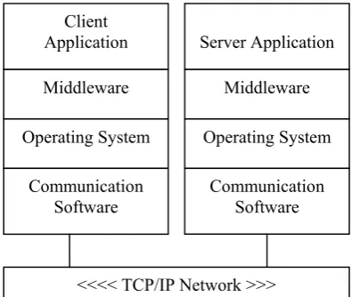
distributed objects that seamlessly communicate with each other [51]. Distributed objects, which can be subject of remote procedure calls, are objects distributed over the network residing in separate address spaces [50, 52 and 53]. A typical distributed processing environment consists of several nodes interconnected by means of a communication network. Each node consists of a CPU and a network interface board.
In some cases where distributed systems need to operate in a heterogeneous environment, it is high likely that different nodes will consist of different hardware and operating systems [53]. In such cases, there is a need for a layer of software as shown in Figure 2.10, which sits above the heterogeneous operating system in order to provide a uniform platform about which the distributed applications can run.
Figure 2.10 Protocol stack incorporating the middleware layer
Chapter 2: Literature Review
2.6.1 Client/Server Architectures
In a client/server model shown in Figure 2.11, the communication between the requesting client and the replying server exhibits a synchronous type of messaging since the client will be blocked once it makes the request until the corresponding reply arrives [56, 56].
Client
Request
Reply
….
Service1
Service n
Server
Figure 2.11 A client/server communication model
Client/server architectures are useful when the nodes on the network need to access centralised information. Substation database of configuration parameters and transaction processing between two relay IEDs are two common examples of this type of architecture [54].
2.6.2 Publish/Subscribe Architectures
Chapter 2: Literature Review
Figure 2.12 Publish/subscribe communication model
Subscribers make subscriptions using definitions of the information they are interested in. Publishers create instances of information, which get forwarded to the subscribers of this information. Distributed real-time communication in the substation environment can as well be realised using the publish/subscribe communication model.
IEDs perform two main tasks in a distributed publish/subscribe system enabling direct message exchange between the communicating IEDs. An IED will either [54]:
• Subscribe to data that it needs, or
• Publish information that it produces.
Any authorised IED may add itself as a subscriber to a particular publisher's list. That subscribing IED will then receive the publications directly from that publisher IED as they become available. Publish/subscribe systems are useful since [54]:
• They are good and quick distributors of large quantities of time-critical information even when unreliable delivery mechanisms are present,
• They can handle very complex data flow patterns, and
• The many-to-many model is very efficient in both bandwidth and latency [59]. Subscriber
1 Subscriber
2 Subscriber
3 Publish
Subscribe ()
Unsubscribe () Push event () Event Service
Publisher 1 Publisher
2 Publisher
Chapter 2: Literature Review
One of the important properties of the publish/subscribe middleware is that the applications running in publishers and subscribers are kept independent of each other. The most important of all is that it handles connections, failures and changes in the network only delivering the data that has been requested by the application software [54]. Although the publish/subscribe model is the best option for use in distributed substation systems, real-time substation systems have other unique needs that can not be served by a multi-purpose designed architecture. Specific architectures are needed to cater for the special needs and requirements of such systems. This is one of the issues being investigated in this thesis discussed in detail in the successive chapters.
2.6.3 Popular Middleware Platforms
Object-Oriented (OO) middleware is the current trend in developing open distributed system environments. It separates object interfaces from their implementations and supports the integration of various software technologies such as operating systems, programming languages and databases. The most important OO middleware platforms are usually listed as Common Object Request Broker Architecture (CORBA), Java-Based Remote Method Invocation (RMI) and Manufacturing Message Specification (MMS).
2.6.3.1 Common Object Request Broker Architecture
Chapter 2: Literature Review
illustrates the components of the CORBA standard. Some of the main parts of the CORBA framework are:
Interface Repository
IDL Compiler
Implementation Repository
SERVANT
DII
IDL
Stubs
CLIENT
OBJREF
ORB
INTERFACE
DSI SkeletonIDL
Object Adapter
Operation()
input arguments output arguments +
return values
ORB CORE
GIOP/IIOP
Figure 2.13 Basic CORBA Architecture [63]
Object Request Broker (ORB): The ORB [60, 61] forms the core of the middleware
facilitating communication between objects by providing a number of services. Such services include resolving object references to locations and marshalling/unmarshalling of parameter and return values when invoking a method on a remote object [13]. CORBA relies on a protocol called the Internet Inter-ORB Protocol (IIOP) for invoking methods on objects [64]. The General Inter-ORB Protocol (GIOP) is a standard protocol that enables interoperability among different CORBA-compliant ORBs [62].
Interface Definition Language (IDL): CORBA IDL [60, 61] specifies the interface of
Chapter 2: Literature Review
Dynamic Invocation Interface (DII): DII permits clients to directly access the
underlying request mechanisms at run time to generate dynamic requests to objects, whose type were not known at the time of the client compilation [62].
Interface and Implementation Repositories: The interface repository contains the
IDL definitions of interfaces for type-checking remote method calls. Correspondingly, the implementation repository contains all implementations of a remote interface at the server-side so that remote objects can be activated on demand [13].
Object Services: These services, also known as CORBA services, add to the basic
capabilities of ORB. They address different aspects of a distributed computing environment ranging from transactional support to security. The two most important ones are the CORBA Naming Service [66] and the CORBA Event Service [67]. The former associates object references with names so that clients and servers can use this for the purpose of locating and advertising CORBA objects. Whereas the latter enables many-to-many communication amongst the CORBA clients through the use of an event channel.
Chapter 2: Literature Review
Although CORBA has found widespread use in the business sector, it offers a lot for industrial applications as well. The use of CORBA in substation automation systems has drawn some attention particularly after the introduction of the UCA 2.0 and IEC 61850 protocols. A number of papers [69, 70] in the literature exploit the use of CORBA technology for implementing the IEC 61850 standard. Although these studies undertaken in [69, 70] have evaluated the use of CORBA as beneficial, the lack of its support for critical real-time requirements is also questioned.
2.6.3.2 Manufacturing Message Specification
MMS [71] is an application layer middleware used for exchanging real-time data and supervisory control information. Virtual Manufacturing Device (VMD), model representation shown in Figure 2.14, is the basic MMS component defining the behaviour of MMS servers from an external MMS client application point of view [72].
The Virtual Manufacturing Device (VMD) Model
Client Application
MMS
Network Interface
objects
` Server Device
variables programs
Network Interface
MMS
VMD
Service Response
S er
Service Request
Chapter 2: Literature Review
MMS provides a rich set of generic services, which can be used by a wide variety of applications independent of their type and industrial area [71, 73]. MMS clients use these services to manipulate objects residing in the servers. MMS objects can be divided into the following categories: variable and type objects, program control objects, event objects, semaphore objects, journal objects, operator station objects and files [74].
Each one of the MMS object types represents a different entity diverse in context and functionality. Each entity is associated with attributes and a simple set of services. For example, journal objects represent time based records contacting the state of an event, or the value of a variable. Clients can make use of the journal services to create, read, delete and clear journal objects [71, 74].
Interoperability and independence are the two most important advantages concerned with the MMS architecture. Interoperability is the ability of network applications to exchange data amongst themselves without the need to create the communication environment. Independence refers to the fact that interoperability can be achieved independent of the developer of the application, network connectivity and the type of function being performed [71]. However, there are also significant drawbacks associated with MMS such as the lack of any explicit support for publish/subscribe architectures. Although MMS preserves many technical advantages, it has not been completely successful. Main criticism to the MMS architecture includes the complexity, the poor performance and the high cost of ISO protocol stacks.
Chapter 2: Literature Review
suitable for such a purpose, is the fact that it provides provisions for supporting both centralised and distributed architectures.
The past few years have witnessed several successful studies based on the implementation of the UCA 2.0 and IEC 61850 application layer protocols making use of the MMS architecture. Quite few research papers exist in the literature detailing such implementations [77-80]. These papers all describe practical applications where the UCA 2.0 and IEC 61850 standards are implemented by means of mapping their abstract objects and services to the MMS object and services. Although MMS is widely believed to be the best option, the mapping process can still get very complex and tedious due to the massive effort that needs to be spent when modifying MMS Object and Service Models (OSMs) to match with the UCA 2.0 or IEC 61850 OSMs. Moreover, an application engineer with the desire of using either one of the standards will not only need to master himself in that standard but also in the use of MMS as well.
Therefore, the mapping process creates extra burden for the application engineers. A solution to this problem will be presented in this thesis eliminating the necessity of the mapping process. The solution involves the OO implementation of the IEC 61850 standard transforming it from an abstract nature into a concrete form. Once the standard is implemented, it will become a real communication mechanism and there will be no need for mapping it on either CORBA or MMS.
![Figure 2.2 Typical integrated substation protection and control system [23]](https://thumb-us.123doks.com/thumbv2/123dok_us/7935463.1317529/38.595.92.489.511.716/figure-typical-integrated-substation-protection-control.webp)
![Figure 2.5 TCP/IP protocols and functional layers [26]](https://thumb-us.123doks.com/thumbv2/123dok_us/7935463.1317529/42.595.100.518.412.621/figure-tcp-ip-protocols-functional-layers.webp)
![Figure 2.6 The merging process [43]](https://thumb-us.123doks.com/thumbv2/123dok_us/7935463.1317529/45.595.199.397.471.588/figure-the-merging-process.webp)
![Figure 2.8 The basic reference model [27]](https://thumb-us.123doks.com/thumbv2/123dok_us/7935463.1317529/48.595.152.442.96.315/figure-the-basic-reference-model.webp)
![Figure 2.9 Relationship between the application and communication interfaces [27]](https://thumb-us.123doks.com/thumbv2/123dok_us/7935463.1317529/49.595.89.504.241.467/figure-relationship-application-communication-interfaces.webp)
![Figure 2.14 The VMD Architecture [71]](https://thumb-us.123doks.com/thumbv2/123dok_us/7935463.1317529/56.595.205.390.457.736/figure-the-vmd-architecture.webp)