ANALYSIS OF PWM CONTROLLED BUCK-BOOST AC
VOLTAGE REGULATOR WITH MITIGATION OF
VOLTAGE SAGS AND SWELLS
P.M. Fayaz Khan
1, S K.Shareef
2, Dr.Abdul Ahad
31
Student, Dept.of EEE, Nimra Collage of Engineering & Technology, Ibrahimpatnam, VJA
2
Assistant Professor,
3Prof &Head, Dept.of EEE,
Nimra Collage Of Engineering & Technology, Ibrahimpatnam(India)
ABSTRACT
Thyristor based controlled method in AC voltage regulator has very low dynamic response and discharge large
amount of harmonic components. And a PWM Controlled Buck-Boost AC Voltage Regulator can efficiently and
economically used in low and medium power applications in the advantage of design simplicity with operation
reliability in a clear withstand of naturally commutated schemes. It has very fast response speed, low harmonics
component distortion and high power factor. In this paper we propose a voltage controller with output peak voltage
and reference as feedback signal and adopts conventional control strategy to regulate the output voltage. The
experimental results of PWM Controlled Buck-Boost AC Voltage Regulator is presented using MATLAB software.
Keywords: Boost Converter, AC Voltage Regulator, PID Controller, Pulse Width Modulation, Potential
Transformer.
I INTRODUCTION
AC voltage regulation is the important part of power conversion methods. There are some types of AC/AC converter
which regulate the input voltage and input current to a lower or higher output voltage. An ideal transformer is
widely used in the voltage regulation control fields such as power system, motor speed control and so on. The
winding ratio is changed by the servo motor or by manual regulation, and it has very low regulation speed. There are
also some other researches which use thyristor phase controlled circuit for voltage regulation. These converters have
been used as a soft starter and a speed regulator of pumps and fans. Even though it has a higher regulating speed
than winding transformer, the low input power factor and the large amount of the low order harmonic current are the
major problems. The size of the passive filter becomes larger.
The input voltage is chopped into segments and the output voltage is regulated by changing the duty ratio of the
control signal. The advantages are nearly sinusoidal input-output currents/voltage waveforms, improved power
factor, reduced harmonic current, a fast response speed and a smaller input filter size. It can protect sensitive
equipment such as a computer or communication equipment; it can also be used to solve power quality problems
the number of the switching devices. Three switches and four switches AC chopper were discussed in previously
presented papers. Different working
Principles have also been presented to ensure the safety of the converter. The switching patterns are critical and an
alternate path has to be established in dead time. DC regenerative snubber capacitor is used to realize the safe
commutation and enhance efficiency. Although there are various researches that focus on the topology of the AC
chopper converter, little attention has been given to the theoretical analysis of the input power factor. In addition,
because most of the previous proposed control methods are open loop control, voltage regulation performance is
restrained.
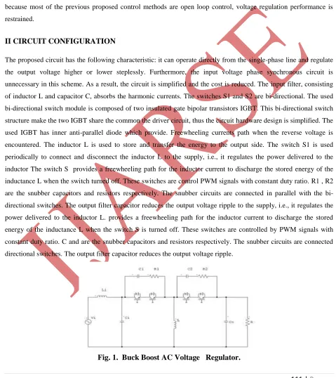
II CIRCUIT CONFIGURATION
The proposed circuit has the following characteristic: it can operate directly from the single-phase line and regulate
the output voltage higher or lower steplessly. Furthermore, the input voltage phase synchronous circuit is
unnecessary in this scheme. As a result, the circuit is simplified and the cost is reduced. The input filter, consisting
of inductor L and capacitor C, absorbs the harmonic currents. The switches S1 and S2 are bi-directional. The used
bi-directional switch module is composed of two insulated gate bipolar transistors IGBT. This bi-directional switch
structure make the two IGBT share the common the driver circuit, thus the circuit hardware design is simplified. The
used IGBT has inner anti-parallel diode which provide. Freewheeling currents path when the reverse voltage is
encountered. The inductor L is used to store and transfer the energy to the output side. The switch S1 is used
periodically to connect and disconnect the inductor L to the supply, i.e., it regulates the power delivered to the
inductor The switch S provides a freewheeling path for the inductor current to discharge the stored energy of the
inductance L when the switch turned off. These switches are control PWM signals with constant duty ratio. R1 , R2
are the snubber capacitors and resistors respectively. The snubber circuits are connected in parallel with the
bi-directional switches. The output filter capacitor reduces the output voltage ripple to the supply, i.e., it regulates the
power delivered to the inductor L. provides a freewheeling path for the inductor current to discharge the stored
energy of the inductance L when the switch S is turned off. These switches are controlled by PWM signals with
constant duty ratio. C and are the snubber capacitors and resistors respectively. The snubber circuits are connected
directional switches. The output filter capacitor reduces the output voltage ripple.
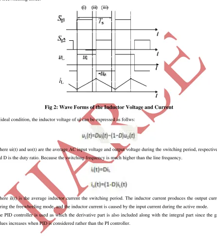
In the switching period, the input voltage ui and the output voltage uo are considered to be constant. When ui>0, the
waveforms of inductor voltage ul and current il. The inductor voltage ul is ui during the active mode or uo during
the freewheeling mode.
Fig 2: Wave Forms of the Inductor Voltage and Current
In ideal condition, the inductor voltage of ul can be expressed as follws:
Where ui(t) and uo(t) are the average AC input voltage and output voltage during the switching period, respectively,
and D is the duty ratio. Because the switching frequency is much higher than the line frequency.
Where il(t) is the average inductor current the switching period. The inductor current produces the output current
during the freewheeling mode, and the inductor current is caused by the input current during the active mode.
The PID controller is used as which the derivative part is also included along with the integral part since the gain
values increases when PID is considered rather than the PI controller.
III SIMULATION RESULTS
To show the feasibility of the proposed analysis method and control strategy, the simulation model of the proposed
Fig 3: PWM Controlled Buck Boost AC Voltage Regulator
According to the diagram, the simulation results are consistent with the theoretical analysis. The chopper type AC
voltage regulator has a high input power factor and can reach the unit power factor in working zone.
Fig 4: The input voltage and current waveforms PWM controlled
Buck-Boost AC voltage regulator
IV CONCLUSION
The PWM Controlled Buck-Boost AC Voltage Regulator has many advantages compared to the thyristor phase
controlled voltage regulator. The analysis method of the input power factor is presented. Compared with other
voltage regulator, the input current is in a sinusoidal waveform with less harmonic components. The output voltage
control system is designed using PID control method and the peak-voltage detector. The simulation results show that
the voltage controller has a good dynamic performance when input voltage swells or sags occur. The PWM
Controlled Buck-Boost AC Voltage Regulator can improve the power factor and reduce the power loss caused by
the reactive and harmonic currents. In addition, it has significant meaning in protecting the voltage sensitive load
against the line voltage swells and sags.
REFERENCES
[1] J.H. Kim, B.D. Min, and B.H. Kwon, “A PWM Buck–Boost AC Chopper Solving the Commutation Problem,” IEEE Transactions On Industrial
[2] Jin Nan, Tang Hou-jun, Lin Wei, “Analysis and Control of BuckBoost Chopper Type AC Voltage Regulator,” IEEE Transactions On Industrial Electronics Vol.36, No.1, pp.33-38, 2009
[3] N.A. Ahmed, Kenji Amei and Masaaki Sakui, “Improved Circuit of AC Choppers for Single-Phase System,” Proceedings of the IEEE Conference PCCON, vol.2, pp. 907-912,2010.
[4] Nabil A. Ahmed, Kenji Amei, and Masaaki Sakui, “A New Configuration of Single-Phase Symmetrical PWM AC Chopper Voltage Controller,” IEEE Transactions On Industrial Electronics, Vol. 46, No. 5, pp. 942-952, 2008.
[5] Shinichiro Fujikura, Akiteru Ueda, and Akihiro Torii, “Analysis of a Three-Phase Buck-Boost AC Chopper
P.M.Fayaz Khan received his Bachelor of technology from EEE- Nimra college of engineering & technology (JNTUK, Kakinada), Vijayawada. He is currently pursuing Masters in Nimra college of engineering & technology in the department of power industrial drives.
Shaik Shareef working as Asst.prof at Nimra college of engineering & technology. He is working from 2010 at Nimra group of colleges. He guided several UG projects & more than 10 PG projects. His areas of interests power systems, power electronics & Electrical Machines.
Dr.Abdul Ahad M.Tech;P.hd (NITK) is an eminent PROFESSOR & HEAD of EEE Nimra group of colleges,& Vice principal of Nimra institute of science & technology. He received M.Tech and was conferred Doctorate from NITK suratkal. He is expertized in power electronics, power systems, special machines, Electrical machines & industrial applications. He has over 15 years of teaching experience. He trains various students for various competitive exams like IES, IAS, GATE, APGENCO, APTRANSCO, DISCOMS and no of national competitive exams. He is the chair person for several national and technical symposiums.