Design and Allocation of UPFC and Generator
in IEEE Bus System for Improvement of
Voltage
Nishant Kumar Bagele1, Santosh kumar2
M.Tech Scholar, Department of Electrical & Electronics Engineering, MITS, Bhopal India1
Professor, Department of Electrical & Electronics Engineering, MITS, Bhopal, India2
ABSTRACT: Optimal location of FACTS (Flexible AC Transmission System) has a significant impact on the improvement of power system stability. In this research, proper placement of UPFC (Unified Power Flow Controller) is identified for voltage stability enhancement of IEEE 14-bus case study. As renewable energy plants are becoming more widely accessible, one trend of power grids’ evolution is decentralization which poses many challenges for grid management. This research work proposes a generator allocation method, based on community structure detection, for placing decentralized generators in IEEE-118 bus system as well as IEEE-300. Node-generator distance (DG) has been taken as an indicator of optimal generators’ locations and the underlying community structure is detected with a series of iterating steps. The existing work analyzed the critical zone location in IEEE 14 bus system and it has been found that bus 14 is the critical zone. Researchers analyzed the power loss at bus 14 in IEEE system. So, in case I, the best location of UPFC has been identified for the improvement of voltage stability of the IEEE 14-bus system in order to maximum compensation of voltage at bus 14 location. It has been demonstrated the effectiveness of properly placing UPFC. In fact, UPFC incorporated through line 9-14 in the critical zone, is very efficient in improving voltage magnitude. Thereby, the optimal placement of the UPFC is highly dependent on the objective of the integration. In other existing work generator location is identified in IEEE 118 bus system as well as IEEE 300 bus system in order to locate the optimal location of generator for proper power distribution. So, in case II, the e ects of the locations of generators is considered in power systems. Based on hybrid node-community structure detection, a generator allocation method is proposed to provide solutions for placing decentralized generators in power systems. Node-generator distance (DG) is used as an indicator of optimal generators’ locations. Simulation results show that the proposed method can e ectively achieve satisfactory allocation solutions as well as enhance the robustness of power systems.
KEYWORDS: Power Grid, UPFC, Generators, IEEE Standard System, Voltage Regulation.
I. INTRODUCTION
Power systems are of vital importance in the economic and industrial growth of countries. Therefore, it is primordial to ensure the continuity and the good quality of the electrical power. Nevertheless, with the continuous escalating power demand, this challenge becomes more and more difficult [1]. Power system is so operating close to its stability limits and several problems associated with system instability are emerging [2, 3]. Faced with these constraints, system planners are always striving to introduce efficient control devices with high response speed. Over the last decades, FACTS devices have opened new perspectives to deal successfully and rapidly with the problems of instability [4]. One of the prominent and powerful FACTS is UPFC. This device is able to control, selectively or simultaneously, phase angle, line impedance and bus voltages, thereby controlling power flow through transmission line and modulating line reactance.
The concept of “smart grid” [6] has emerged. Power generators based on renewable sources are introduced to the power systems. Compared to conventional power plants, these new energy generators are relatively small but in large quantity. One trend of the evolution is that the power grids are becoming more decentralized in terms of power generation. As the reliable operation of power grids is highly relevant to society, their robustness has always drawn much attention of the researchers and electrical engineers. By modelling power stations as nodes and transmission lines as links, complex network models can provide a comprehensive analysis of power systems. Previous works have investigated the influence of power generators’ decentralized allocation on the robustness of power systems from the perspective of complex networks [7].
The phenomenon of voltage instability is classified as local, but can lead to a widespread problem. In fact, after a series of disturbances, the voltage in one part or in the whole network can be very low, which leads to a voltage drop.The current flow through the transmission line is a function of line impedance, amplitude and phase angle of the bus voltage [8,9,10]. If these parameters can be controlled, the flow of current through the transmission line can be controlled in a predetermined manner.Many devices contribute to the compensation of the reactive power and to the voltage curve. Because of its physical properties, a transmission line provides reactive power at low load and consumes it under high load conditions [11]. The grid voltages are controlled by power and reactive energy consumption. The objectives of this research work are as follows:
Design of IEEE-14 bus system and comparative analysis depending on different allocation of UPFC. To improve voltage stability.
Design IEEE 118 Bus and IEEE 300 Bus based on generator allocation strategies.
II. METHODOLOGY
The proposed methodology is based on improving the voltage quality under IEEE standard bus system. This research work is intended with the proper placement of UPFC location as well as generator location in order to get regulated and stabilized voltage output in grid system. For this the dissertation work is divided into two case studies, i.e. case study I for proper placement of UPFC location and case study II for proper placement of generators for proper distribution of power to consumer nodes [12,13].
Case Study -I
In this case the standard IEEE 14-bus network is used for the numerical simulations. This system contains two generators each one is equipped with voltage and speed regulators and three synchronous compensators to produce reactive power. It also has two transformers with two windings, a three-winding transformer, fifteen transmission lines and eleven loads. The IEEE 14-bus network can be decomposed into: a transmission system referred by « zone A » and a distribution one referred by « zone B » interconnected through three step-down transformers. To identify the critical zone, this research work proceeded by an incremental load increase of each zone separately and it is found that bus 14 is the critical zone of IEEE bus system [14].
Case Study -II
This section introduced the method used to assess the robustness of power systems. Basic Model
In this model there are four kinds of nodes, namely, the generation node, the consumer node, the distribution node and the transformer node.
Consumer Nodes (Loads): A consumer node i dissipates power, and at the circuit level, it sinks current Ii. The current value is negative as the node consumes power, i.e.,
[− … … … … . … … … …− ]∗ = (1)
where V=[………….vi vjvk……….]T
vnis voltage at node n
Yij is the admittance of the transmission line connecting node I and j. If there is no transmission line between nodes
i and j, Yij= 0.
Distribution Nodes : A distribution node j is a connecting node that nether produces nor consumes power.
[0 … … … … . … … … … 0]∗ = (2)
where yn = 1, and vn is the voltage of node n.
Transformer Nodes: Transformer nodes connect the high-voltage grids with mid-voltage or low-voltage grids. The currents flowing in the transmission lines can be calculated as:
= − ∗ (3)
Weadopted the standard IEEE 118-bus and 300-bus network for the numericalsimulations.
Node-Generator Distance and Hybrid Algorithm for Allocation of Generators
In this research, we propose a generator allocation method, based on community structure detection, for placing decentralized generators. We take node-generator distance (DG) as an indicator of optimal generators’ locations and the underlying community structure is detected with a series of iterating steps.
A metric called node-generator distance (DG) is used for measuring the accessibility to generators of all consumers. DG is defined as the average e ective resistance (distance) to a nearest generator of all consumer nodes, i.e.,
= 1
( − ) ( ) (4)
whereN\G is the set of nodes excluding the generator nodes, nis the total number of nodes, and g is the number ofgenerators in the network. d(i) is the resistance distance of node i to itsnearest generator, as d(i) = min{Ris, s ∈ G}. R
isthe electrical distance between nodes i and s.
DG indicates the extent of decentralization, whose value can be smaller when one big power plant is replaced by several small decentralized plants or when the same number of generators are more evenly distributed in the network. Thus, there should be community structures underlying the huge inter connected power system. If we can detect these underlying community structures and place generators evenly in the communities, DG can be e ectively reduced [15].
Hybrid Algorithm for Allocation of Generators
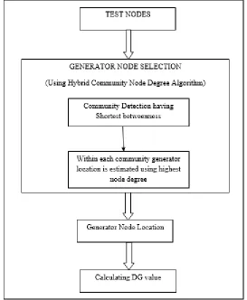
Power grid networks evolve under geographical and anthropic influences, with spacial and human residential embeddings. Regions exist in both systems. Within a region (community)the nodes are closely inter connected, and among the regions the connections are sparser. Thus, there should be community structures underlying the huge inter connected power system. If we can detect these underlying community structures and place generators evenly in the communities, DG can be e ectively reduced. In this algorithm the consumer and generator nodes of IEEE 118 bus system as well as IEEE 300 bus system are distributed and grouped together using community detection algorithm. After dividing the IEEE nodes into communities, generator location is detected in each community. The nodes having the highest degree as well as having lowest betweenness among community in each community is selected as a location for generator for proper distribution of power in case of any failure in the grid system or in case of failure of any generator node. Figure 3.3 shows the flow chart of case II work.
In proposed algorithm, first of all, we detect a power grid’s community structure with the method of finding shortest distance and betweenness among nodes. the links with high betweenness carries heavy tra c and they are likely to be the links among communities. By deleting links with highest betweenness, the network can be decomposed into communities gradually.
For any link between nodes, the betweenness is calculated as:
= ( ) (5)
Where, σij is the total number of shortest paths from node i to node j, and σij(p) is the number of those paths that pass
through link p.
= 1
( ) (6)
In this algorithm
The algorithm for finding betweeness is as follows: Procedure {Community Detection}
{
1. Calculate betweenness for all links between nodes 2. find the link with the highest betweenness 3. Remove it from the node list
4. Recalculate betweenness for all remaining links 5. Repeat Step 2
}
After allocating communities then within each community generator location is estimated using highest node degree as well as having lowest betweenness at node among community. For IEEE 118 bus system 10 communities with 10 generator location are calculated as well as for IEEE 300 bus system 24 communities with 24 generator location are calculated.
Figure 1: Flow Chart of Hybrid Algorithm for Allocation of Generators
III.RESULT ANALYSIS
Results Analysis for UPFC Placement
In this case the standard IEEE 14-bus network is used for the numerical simulations. The IEEE 14-bus network can be decomposed into: a transmission system (69 KV) referred by « zone A » and a distribution one (13.8 KV) referred by « zone B » interconnected through three step-down transformers. The part of the network experiencing voltage collapse rapidly is considered as the critical zone. According to steady state, we noted that bus 14 is the most insecure bus; it has got the lowest magnitude compared to the other buses. For this reason, we choose to adopt this bus as an index for voltage stability assessment. This case is analyzed by placing UPFC at different locations in IEEE 14 bus system. For this research eight UPFC locations are analyzed whose voltage graphs are represented below:
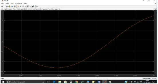
Figure 2: Voltage at Bus 14 in IEEE 14 Bus System without UPFC
Figure 2 represents the voltage graph using without UPFC condition for IEEE bus system at bus 14 as it is the critical zone of IEEE 14 standard bus system.
Figure 3: Voltage at Bus 14 in IEEE 14 Bus System with UPFC Placement between Bus 9 and 10
Figure 4: Voltage at Bus 14 in IEEE 14 Bus System with UPFC Placement between Bus 9 and 13
Figure 4 represents the voltage graph using with UPFC conditionbetween 9 and 13 for IEEE bus system at bus 14 as it is the critical zone of IEEE 14 standard bus system.
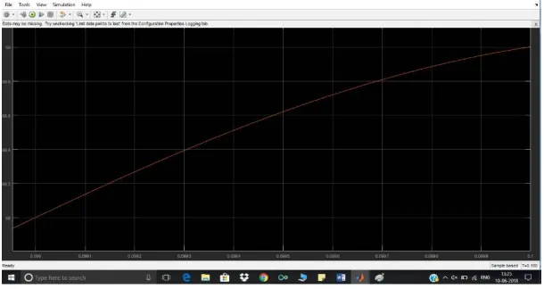
Figure 5: Voltage at Bus 14 in IEEE 14 Bus System with UPFC Placement between Bus 9 and 14
Figure 5 represents the voltage graph using with UPFC conditionbetween 9 and 14 for IEEE bus system at bus 14 as it is the critical zone of IEEE 14 standard bus system.
Figure 6 represents the voltage graph using with UPFC conditionbetween 10 and 11 for IEEE bus system at bus 14 as it is the critical zone of IEEE 14 standard bus system.
Figure 7: Voltage at Bus 14 in IEEE 14 Bus System with UPFC Placement between Bus 10 and 14
Figure7represents the voltage graph using with UPFC conditionbetween 10 and 14 for IEEE bus system at bus 14 as it is the critical zone of IEEE 14 standard bus system.
Figure 8: Voltage at Bus 14 in IEEE 14 Bus System with UPFC Placement between Bus 11 and 12
Figure8represents the voltage graph using with UPFC conditionbetween 11and 12 for IEEE bus system at bus 14 as it is the critical zone of IEEE 14 standard bus system.
Figure9represents the voltage graph using with UPFC conditionbetween 11 and 14 for IEEE bus system at bus 14 as it is the critical zone of IEEE 14 standard bus system
Figure 10: Voltage at Bus 14 in IEEE 14 Bus System with UPFC Placement between Bus 12 and 14
Figure10represents the voltage graph using with UPFC conditionbetween 12and 14 for IEEE bus system at bus 14 as it is the critical zone of IEEE 14 standard bus system
After analyzing the voltage stability in IEEE 14 bus system it has been concluded that UPFC location between 9 and 14 is the best location to be placed in order to stabilize the voltage fluctuation in the network. Table I represents the result analysis of all the locations.
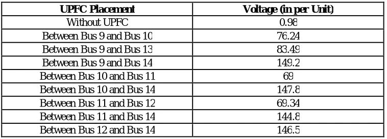
Table I: Result Analysis of UPFC Placement in IEEE 14 Bus System
UPFC Placement Voltage (in per Unit)
Without UPFC 0.98
Between Bus 9 and Bus 10 76.24
Between Bus 9 and Bus 13 83.49
Between Bus 9 and Bus 14 149.2
Between Bus 10 and Bus 11 69
Between Bus 10 and Bus 14 147.8 Between Bus 11 and Bus 12 69.34 Between Bus 11 and Bus 14 144.8 Between Bus 12 and Bus 14 146.5
Results Analysis for Generator Location
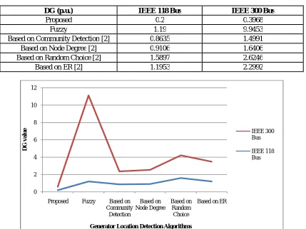
TableII below gives the DG values of IEEE 118 Busand IEEE 300 Bus based on di erent generator allocation strategies, with thepercentage of generators all fixed at 8% i.e. 10 and 24 generators respectively.
Table II: Result Analysis of Generator Placement in IEEE 118 and IEEE 300 Bus System
DG (p.u.) IEEE 118 Bus IEEE 300 Bus
Proposed 0.2 0.3968
Fuzzy 1.19 9.9453
Based on Community Detection [2] 0.8635 1.4991
Based on Node Degree [2] 0.9106 1.6406
Based on Random Choice [2] 1.5897 2.6246
Based on ER [2] 1.1953 2.2992
Figure 11: Comparative Analysis of DG Value for IEEE 118 and IEEE 300 Standard Bus System
IV.CONCLUSION
This research work is intended towards finding the optimal location of UPFC devices as well as generator nodes for proper voltage regulation in entire network. For this two scenarios or cases are identified in which first of all UPFC location is identified in order to compensate the voltage requirement in critical zone of the entire network under any disturbance in network. Whereas in another case proper generator location is identified in order to compensate the power supply in entire network for IEEE 118 and IEEE 300 bus system.
In case I, the best location of UPFC had been identified for the improvement of voltage stability of the IEEE 14-bus system. We have demonstrated the effectiveness of properly placing UPFC. In case II, the e ects of the locations of generators is considered in power systems. Based on hybrid node-community structure detection, we propose a generator allocation method to provide solutions for placing decentralized generators in power systems. Node-generator distance (DG) is used as an indicator of optimal generators’ locations.
Following conclusion are analyzed in this research work:
In case I, UPFC incorporated through line 9-14 in the critical zone i.e. bus 14, is very efficient in improving voltage magnitude.
Thereby, the optimal placement of the UPFC is highly dependent on the objective of the integration.
Simulation results in case II showed that the proposed work has achieved satisfactory allocation solutions as well as enhance the robustness of power systems.
0 2 4 6 8 10 12
Proposed Fuzzy Based on
Community Detection Based on Node Degree Based on Random Choice
Based on ER
D G v a lu e
Generator Location Detection Algorithms
IEEE 300 Bus
In future work this research will be extended while determining the efficient UPFC location in IEEE 39, IEEE 69 and IEEE 118 bus system for improving voltage magnitude, reducing active power losses as well as increasing maximum loading capacity of the network.
REFERENCES
[1] J.SteffyAmirtham, V, Uma, “Optimal Location of Unified Power Flow Controller Enhancing System Security”, IEEE, 2017.
[2] Xi Zhang and Chi K. Tse, “An E ective Generator-Allocating Method to Enhance the Robustness of Power Grid”, IEEE 2016.
[3] Mausam Yadav ; Ankur Soni, “Improvement of power flow and voltage stability using unified power flow controller”, IEEE, 2016.
[4] H. Jmii, A. Meddeb, S. Chebbi, “Proper placement of UPFC for the improvement of voltage stability of IEEE-14 bus system”, IEEE, 2016.
[5] X. Zhang and C. K. Tse, “Assessment of robustness of power systems from a network perspective,” IEEE Journal on Emerging and Selected
Topics in Circuits and Systems, vol. 5, no. 3, pp. 456–464, 2015.
[6] Fadi M. Albatsh, Shameem Ahmad, Saad Mekhilef, “Optimal Placement of Unified Power Flow Controllers to Improve Dynamic Voltage
Stability Using Power System Variable Based Voltage Stability Indices”, PLOS, 2015.
[7] Xi Zhang ; Chi K. Tse, “Assessment of Robustness of Power Systems from the Perspective of Complex Networks”, IEEE, 2015.
[8] P Harshavardhan Reddy, M Padma Lalitha, Satish Babu, “Enhancement of Voltage Stability by optimal location of UPFC using MPSO and
Power Flow Analysis using ECI Algorithm”, IOSR Journal of Electrical and Electronics Engineering, 2014.
[9] Lokman H. Hassan, Mahmoud M. Haider, A. F. Almurib, and Kashem M. Muttaqi, “ A coordinated design of PSSs and UPFC-based stabilizer
using Genetic Algorithm”, IEEE Trans. on Industry Applications, vol. 50, no. 5, pp. 2957-2966, 2014.
[10] Seung-MookBaek, Jung-Wook Park and Hiskens, “I.A.Optimal Tuning for Linear and Nonlinear Parameters of Power System Stabilizers in
Hybrid System Modeling” IEEE Trans. on Industry Applications, vol. 45, no. 1, pp. 87-97, 2014.
[11] S. Pahwa, D. Weerasinghe, C. Scoglio, and R. Miller, “A complex networks approach for sizing and siting of distributed generators in the
distribution system,” in Proc. NAPS, pp. 1–5, 2013.
[12] M. Rohden, A. Sorge, M. Timme, and D. Witthaut, “Self-organized synchronization in decentralized power grids,” Physical Review Letters,
vol. 109, no. 6, pp. 64–101, 2012.
[13] Wartana, Jai Govind Singh, WeerakornOngsakul, “Optimal Placement of UPFC for Maximizing System Loadability and Minimize Active
Power Losses by NSGA-II”, IEEE, 2012.
[14] V.P.Rajderkar and V.K.Chandrakar, “Comparison of series FACTS Devices Via Optimal Location in a Power System for Congestion
Management”, APPEEC Conference, 2009, pp. 534-543.