Modeling and Analysis of Non-Pneumatic Tyre by Using
Ansys
1.NANDIKANTI SUPRIYA REDDY ,2. Mr. G. VINOD REDDY
1 Pg Scholar,Department of Mechanical Engineering, elleniki college of enginnering and
technology
2.Asst.Prof, Department of Mechanical Engineering, elleniki college of enginnering and
technology
Abstract
—
Non-pneumatic tires (NPT) or Tweels are the new developments at present increased attention because of potential advantages over pneumatic tires as these are having low mass, no run flat, good contact pressure distribution, and low rolling resistance (RR).
In the pres work focuses on modeling and design with reference to vertical stiffness properties, contact pressure and energy loss due to rolling. The finite element analysis using Ansys software is used to study parametrically the vertical stiffness effect and the contact pressure influence with the rolling resistance response by considering the three design variables such as 1. Spokes thickness, 2. Thickness of shear band and 3. Shear modulus.
It is observed that the first two are geometric dependent and where as the third the material dependent parameter. The contact pressure will have more response or effect on the tyre analysis. During the analysis it is assumed to consider the static contact pressure of a non pneumatic tyre spokes as a function of vertical loads which are applied at the centre of hub. The shear band is as a rolling resistance from the shear friction of elastomers.
The design is modeled with CATIA. Where the hub of the Non-pneumatic tire is made with the Aluminium Alloy (Al:7075-T6) and the spokes and shear band with the PU and inner reinforcement and the outer reinforcement are made with the high strength steel (AISI-4340) and the thread is made up of rubber. The design is modeled for 3D lattice honeycomb spoke and the linear spokes. The models were imported to ANSYS work bench to evaluate the results of deflection of the pneumatic tire, von misses stress of the pneumatic tire and the contact pressure of the Non-pneumatic tire with the road. The load at the hub centre were 3500N and 4000N respectively. Results indicate that all the design variables have significant effect on RR, with the shear band thickness and shear modulus having the greater effect. The Non-pneumatic tire is modeled in CATIA and analysis is validated through ANSYS.
1. INTRODUCTION
The comfort and safety for a vehicle mainly depends on the good working state and mostly obtained between the components such as vehicle suspension system during
any external disturbances occurred by interaction with a roughened ground while advising the driver to keep an efficient and safe control over his vehicle. In a vehicle if one of those components is badly designed, manufactured, mounted or used, severe consequences which can disturb the comfort of people inside the vehicle while driving and even it consider their safety. Purpose as vehicles has designed more robust, reliable and sophisticated, drivers became less awareness over their tires. Tires have significantly developed in terms of safety, performance and wear, but they still need more attention than most of the vehicle components.
There are many issues or problems that can result in a tire failure (puncture or blowout). Such as unpleasant event that can occur at any instant when a tire loses suddenly or gradually its internal air pressure. The pressure drop which prevents the tire from accomplishing its principal task; that is to support the weight of the vehicle and thus, makes the driver failure to maintain a straight and safe trajectory which leads very frequently to a harmful vehicle accident. The development of non-pneumatic tires (NPT) from the Michelin Tweel is received increasing attention due to the potential advantages over the pneumatic tires.
Non Pneumatic Tyre design are driven by few characteristic properties such as rolling resistance, mass, stiffness, durability and contact pressure mainly. Rolling resistance is one of the major characteristics of interest that contributes to the fuel consumption of vehicles. Stiffness and contact pressure distribution are major properties to be addressed when designing a Non Pneumatic Tyre.
A tire is a product of complex engineered composites. It contains mainly a reinforced rubber toroid mounted to a metallic rim. The air trapped inside the tire creates an inflation pressure which is responsible for carrying the
load, transmitting forces, absorbing shock, providing grip and resisting wear.
1.1 Non-Pneumatic Tire Design (NPTD)
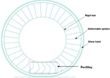
The Non Pneumatic Tyre is consists of a composite ring, with at least two circumferential reinforcements separated by a radial distance and is treated as shear beam then it made of a low modulus material which is sandwiched with the reinforcements. During operation, the material with the reinforcements is loaded to shear and deforms in pure shear.
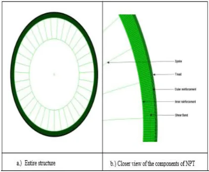
A uniform, and the distribution of pairs of spoke is designed with the ring and to the hub of the wheel. They then deform by buckling. Figure 1.1 represents the structure of the Non Pneumatic Tyre model.
In the design of shear beam and spokes which allows the uniform surface contact pressure with the road surface under the load. With moulding the spokes and the ring together are manufactured with the reinforcements. The outer ring bonded with rubber thread to provide traction.
Figure 1.1 Non-Pneumatic Tire Model (NPTM)
When the load is applied on the Non Pneumatic Tyre then the hub center, and the composite ring then flattens at the contact surface, which then forms a patch contact. There is a buckling deformation in the spokes with the load applied.
The spokes then under tension without undergoing the deformation. The buckling behaviour of the Tyre is shown in Figure 1.2 when the static load is acted upon.
Figure 1.2 Deformed tyre under the load
The Non Pneumatic Tyres with the 2D hexagonal cellular spokes and 3-D hexagonal cellular spokes are to have a load carrying capacity and they are analysed under the contact pressures which are given as a vertical loading. Because of complexity of
geometric and material non linearity’s the analysis should be of large deformation induced geometric nonlinearity, FEA software, ANSYS, is used for computation for contact pressure of Tyres.
Fig 1.3 Model of a honey comb lattice structure
1.2 Resistance of Rolling
Figure 1.4 Variation of stress with strain
It is considered to be the main contributor to the energy loss in tires are due to Hysteresis as it is mainly contributes 95% of the total energy loss in tires. Therefore the viscoelastic materials used in tyres will results in energy loss thereby resulting in rolling resistance also.
Friction between the road and the tyre is the other factor resulting in energy loss which typically occurs because of the slip of the tire on the road surface. This factor also makes to contribute to a level of 8 % of the total energy loss in tires.
The third most and the least factor influencing to the energy loss in tires is Wind age. This is due to the aerodynamic resistance over the vehicle. It makes to be at the level of 3% of the total energy loss in tires. The rolling resistance (RR) of the tyre can be part of the energy dissipated or/ and energy lost per distance rolled during the motion is given by
eq(1.1)
Where, FR = Rolling resistance, Wd = Energy dissipated or energy lost, and
D = Distance rolled by the tire.
The coefficient of rolling resistance is given by the equation
eq(1.2)
crr = coefficient of rolling resistance
z = is the shrinkage depth or
deflection = δ
d = diameter of the wheel
The rolling resistance force is given by the equation is given by
Eq(1.3)
Crr = Coefficient of rolling resistance
N = Normal force or load
Rolling resistance of the tire is depends on the vehicle fuel consumption and it also increases the temperature in the tire. In the current scenario of automotive fleet, tires have a short lever on (i) fuel economy; roughly 10% decrease in rolling resistance and 1% better fuel economy. (ii) Rolling resistance is influenced by a number of factors which are the i. load, ii. tire geometry, iii. speed, iv. temperature, and v. contact pressure.
2. PROBLEM STATEMENT
The objective of the work is to model, simulate and perform static analysis of a Non Pneumatic tyre used in a four wheeler under working conditions. The Non Pneumatic tyre consists of hub (aluminium alloy), spokes(polyurethane), inner reinforcement (high strength steel), shear band (polyurethane), outer reinforcement (high strength steel) and thread (rubber).
induced, deformation and contact pressure developed. Based on deformation of the Non Pneumatic tyre, the rolling resistance is calculated. Based on this the best geometric structure for a Non Pneumatic tyre for the given working conditions is realised.
Fig 2.1 Two dimensional view of linear spoke Non Pneumatic tyre
Fig 2.2 Two dimensional honey comb model of a Non Pneumatic Tyre
3.RESEARCHMETHODOLOGY
In this thesis the Non Pneumatic Tyre is modelled in CATIA. The dimensions of the Non Pneumatic Tyre are obtained from previous study for 3D honey comb lattice structure and for the linear spokes the dimensions are taken arbitrary.
The Non Pneumatic tyre is modelled in CATIA and the models are imported to the ANSYS 15 in IGES format. Analysis is done in ANSYS 15 for the deflection, Von mises stress and maximum contact pressure of the Non Pneumatic Tyre.
3.1 Dimension of the Non Pneumatic Tyre with linear spoke
Outer diameter of the NPT =593mm
Thickness of the thread = 5mm
Outer reinforcement diameter=583mm
Thickness of the outer reinforcement=4mm
Shear band diameter=575mm
Thickness of the shear band=12.5mm
Inner reinforcement diameter=550mm
Thickness of the inner reinforcement=3mm
Length of the spokes =150mm
Thickness of the spoke=9mm
Width of the spoke =100mm
Width of the NPT =100mm
In this thesis the design of NPT has
modelled all the parts separately and all the part diagrams were assembled with constraining them without gap.
Dimensions of the 3D honey comb lattice structure of NPT
The design of 3D honeycomb lattice
spokes for the NPT. The outer dimensions of the NPT are considered form BMW mini tyre and the 3D honeycomb structure are taken from the previous studies.
The honey comb lattice design is considered from previous studies and an optimal value of the structure is taken into the consideration.
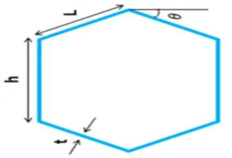
Fig 3.2 Honey comb unit cell structure for spoke
Hexagonal honeycombs are modelled with a cell wall thickness(t), the cell angle(θ), vertical cell length(h) and the inclined cell length(l). When designing honeycombs, numerous configurations are available with cell angle(θ), cell height(h), and cell length(l).The dimensions of the honeycomb spokes which are obtained arbitrarily. It contains three different types of hexagonal spoke. These dimensions are shown in table 1.
Table 1 Dimensions of honey comb unit cell structure
Outer diameter of the NPT =593mm
Thickness of the thread = 5mm
Outer reinforcement diameter=583mm
Thickness of the outer reinforcement=4mm
Shear band diameter=575mm
Thickness of the shear band=12.5mm
Inner reinforcement diameter=550mm
Thickness of the inner reinforcement=3mm
Length of the 3D honeycomb lattice structure =150mm
Honey comb cell wall thickness is =5mm
Hub diameter = 250mm
Width of the NPT =100mm
In this thesis the design of NPT has modelled all the parts separately and all the part diagrams were assembled with constraining them without gap.
From the above dimensions, type C unit cell dimension is considered because, from the previous study the type C is having less deflection, the von misses stress is low and having minimum contact pressure.
Fig 3.3 Model of NPT with honey comb lattice structure in CATIA
Material properties
Material Density,
ρ(Kg/m3
.
Young modulus,, E(MPa)
Poisons ratio, ν
Shear modulus,
µ0(MPa)
Aluminium alloy
2800 72 x 103 0.33 26x103
Polyurethane 1200 32 0.49 10.81
High
strength steel ANSI 4340
7800 210 x 103 0.29 80x103
Rubber 1043 11.9 0.49 4
4. RESULTS AND ANALYSIS
Ansys Simulation Results for Linear Spoke Non Pneumatic Tyre
Two different cases has analysed for each model of linear spoke Non Pneumatic Tyre, through ANSYS successfully.
Case(1): for load of 3500N at the hub centre for linear spokes Non Pneumatic Tyre.
Result showing the deflection of the Non Pneumatic Tyre for a load of 3500N
Fig 4.1 Deflection for load of 3500N
Maximum deflection of the Non Pneumatic Tyre with respect to road for a load of 3500N =3.57932mm
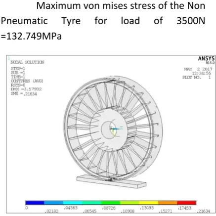
Fig 4.2 Von Mises stress for load of 3500N
Maximum von mises stress of the Non Pneumatic Tyre for load of 3500N =132.749MPa
Fig 4.3 Maximum contact pressure for load of 3500N
Maximum contact pressure of Non Pneumatic Tyre for load of 3500N=0.21634Mpa
Fig 4.4Deflection for load of 4000N
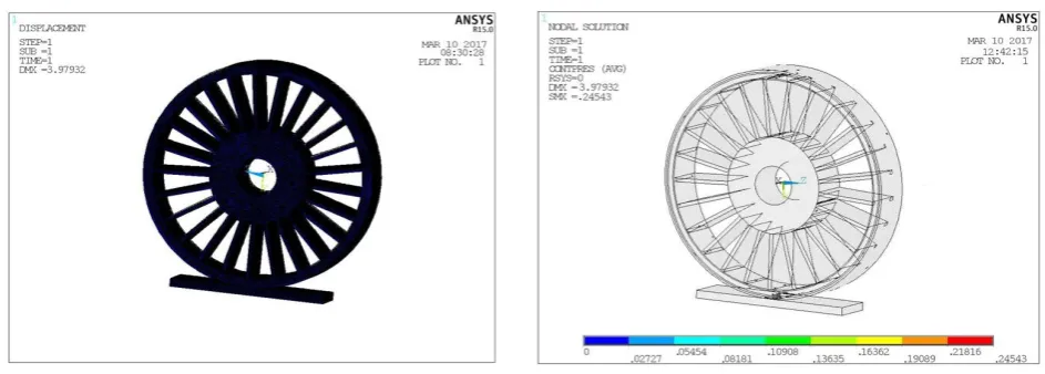
Maximum deflection of the Non Pneumatic Tyre with respect to road for a load of 4000N = 3.97932mm
Fig 4.5 Von Mises stress for load of 4000N
Maximum von mises stress of the Non Pneumatic Tyre for load of 4000N = 150.749MPa
Fig 4.6 Maximum contact pressure for load of 4000N
Maximum contact pressure of the Non Pneumatic Tyre for load of 4000N = 0.24543Mpa
ANSYS Simulation Results for 3D Honey Comb Lattice Structure Non-Pneumatic Tyre
Two different cases has analysed for each model of 3D honey comb lattice structure spoke Non Pneumatic Tyre, through ANSYS successfully.
Case(1): for load of 3500N at the hub centre for 3D honeycomb lattice structure spokes Non Pneumatic Tyre.
Fig 4.7 Deflection for load of 3500N
Fig 4.8 Von Mises stress for load of 3500N
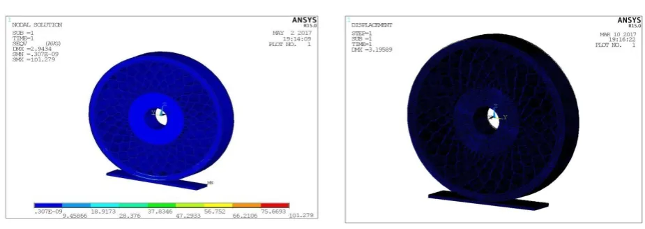
Maximum von mises stress of the Non Pneumatic Tyre for load of 3500N = 101.279Mpa
Fig4.9 Maximum contact pressure for load of 3500N
Maximum contact pressure of the Non Pneumatic Tyre for load of 3500N=0.28156Mpa
Case(2): for load of 4000N at the hub centre for 3D honeycomb lattice structure spoke Non Pneumatic Tyre
Fig4.10 Deflection for load of 4000N
Maximum deflection of the Non Pneumatic Tyre with respect to road for a load of 4000N = 3.19589mm
4.11 Von Mises stress for load of 4000N
4.12 Maximum contact pressure for load of 4000N
Maximum contact pressure of the Non Pneumatic Tyre for load of 4000N=0.29331Mpa
5. CALCULATION OF ROLLING RESISTANCE COEFFICIENT
The coefficient of rolling resistance is given by the equation
crr= coefficient of rolling resistance
z= is the shrinkage depth or
deflection = δ
d = diameter of the wheel
Coefficient of rolling resistance for a load of 3500N of linear spokes NPT is
Coefficient of rolling resistance for a load of 4000N of linear spokes NPT is
Coefficient of rolling resistance for a load of 3500N of 3D honeycomb NPT is
Coefficient of rolling resistance for a load of 4000N of 3D honeycomb NPT is
5.1 Calculations of Rolling Resistance Force
The rolling resistance force is given by the equation is given by
Crr = Coefficient of rolling
resistance
N = Normal force or load
Rolling resistance force for a load of 3500N of linear spoke NPT is
Rolling resistance force for a load of 4000N of linear spoke NPT is
Rolling resistance force for a load of 3500N of 3D honey comb NPT is
N
Rolling resistance force for a load of 4000N of 3D honey comb NPT is
Table 3 Results of Non Pneumatic Tyre
Linear spoke @ load 3500N
Linear spoke @ load 4000N
3D
honeycomb spoke @ load 3500N
3D
honeycomb spoke @ load 4000N
Deflection(δ) in (mm)
3.57932 3.97932 2.9434 3.19589
Von mises stress in (MPa)
132.749 150.749 101.279 116.163
Contact pressure
In (MPa)
0.21634 0.24543 0.28156 0.29331
Coefficient of Rolling Resistance
0.0776913 0.081917 0.0704526 0.0734122
Rolling Resistance force( N )
271.91 327.668 246.58 293.64
6. CONCLUSION
The percentage reduction in Rolling Resistance of 3D honeycomb lattice structure of Non Pneumatic Tyre to the linear spokes of Non Pneumatic Tyre is 11.13% and 10.38% for load of 3500N and 4000N respectively. The contact pressure of 3D
honeycomb lattice structure of Non Pneumatic Tyre to the linear spokes of Non Pneumatic Tyre has increased by 27.69% and 16.32% for a load of 3500N and 4000N respectively. The percentage reduction in Rolling
Resistance force of 3D honeycomb lattice structure of Non Pneumatic
Tyre to the linear spokes for Non Pneumatic Tyre is 11.27% and 10.38%.
Deflection of the 3D honeycomb Non Pneumatic Tyre is less than the linear spoke Non Pneumatic Tyre.
3D honeycomb lattice structure of Non Pneumatic Tyre is giving better performance compared to the linear spokes Non Pneumatic Tyre.
REFERENCES
model for polyurethane foam: MIPS, Université de Haute Alsace, 21ème Congrès Français de Mécanique.
3. Rutika Gotad, Sukanya Yadav , Aarti Dung. , Tweel Tire Technology of NPT In Science & Engineering (IJAFRSE). 4. C. Manibaalan, Balamurugan.S, Keshore, Dr.Joshi.C.Haran.
Static analysis of airless tire, in the IJSER Publications, V3, n8, 2013, ISSN 2250-3153.
5. A.M. Aboul-Yazid, M.A.A. Emam, S. Shaaban1 and M.A. El-Nashar. , Effect of spokes structures on characteristics performance of non-pneumatic tires (IJAME) ISSN: 2229-8649, ISSN: 2180-1606.
6. Anuj Suhag, Rahul Dayal. In this method Static Analysis on Custom Polyurethane Spokes of Airless Tire, which is obtained in IJSER , V3, Issue 11, 2013, ISSN 2250-3153. 7. Kwangwon Kim, Seunghye Kim, Jaehyung Ju and Doo-Man
Kim. , Contact pressure of a non-pneumatic tire with three dimensional cellular spokes, proceedings of the ASME 2011 International Mechanical Engineering Congress & Exposition IMECE2011 November 11-17, 2011, Denver, Colorado, USA.
8. K.Periasamya, S.Vijayanb. Design and development of air-less car tire, Sept., 2014. ©IJAET ISSN: 22311963. 9. Niranjan Thyagaraja Clemson University, Determination
Of A Novel Non Pneumatic Wheel Shear Beam For Low Rolling Resistance,11-2005.