Comparative Analysis of 31-level
Asymmetrical Inverter Using Different
Control Techniques
Madhusudhana J1, Rakshitha R Prabhu2, P S Puttaswamy3
Assistant Professor, Dept. of Electrical Engineering, UVCE, Bangalore, Karnataka, India1
PG Student [PE], Dept. of Electrical Engineering, UVCE, Bangalore, Karnataka, India2
Professor, Dept. of Electrical and Electronics, PESCE, Mandya, Karnataka, India3
ABSTRACT: Multilevel inverters(MLI) generate stepped AC output voltage using input DC voltage sources. For a Cascade H-bridge (CHB) MLI, several H-bridges are connected in cascade and each of the H-bridges consists of a separate DC source. In case of Symmetrical CHB inverters, the magnitudes of the input voltage sources are identical. Where as in case of Asymmetrical CHB inverters the input voltage sources are unequal,thus requiring less number of H-bridges to produce higher level in the output waveform. In this paper, a Cascaded H-Bridge Multilevel Inverter in asymmetrical configuration with four unequal DC sources is operated to produce 31-level output using control techniques such as Equal Phase Angle and Genetic Algorithm. In Equal Phase Angle technique the switching angles are considered to be spaced at equal intervals to obtain the output voltage. Where as in Genetic Algorithm technique, the SHE non linear equations are solved using MATLAB code to obtain optimum values of the switching angles. The circuit for both the techniques are simulated with MATLAB/ Simulink software & the results obtained are analyzed and presented.
KEYWORDS: Multilevel Inverter (MLI), Cascaded H-Bridge (CHB), Equal Phase Angle Technique, Genetic Algorithm (GA), Selective Harmonic Elimination (SHE), Total Harmonic Distortion (THD).
I. INTRODUCTION
With Multilevel Inverter (MLI) is broadly used in high & medium power applications. Different types of MLI are present like: Flying Capacitor Inverter (FC) [1], Neutral Point Clamped Inverter (NPC) [2] & Cascaded H-Bridge Inverter (CHB) [3]. NPC topology makes use of large number of diodes to give different voltage levels to the series connected capacitor banks making it unsuitable. FC topology uses capacitors to transfer the voltage to the electrical devices but suffers from voltage imbalance[4]. In CHB topology, several H-Bridges are connected in cascaded manner & each H-Bridge consists of a separate DC voltage source. Among these topologies, CHB is preferred due to its simple structure, easy expandability to higher voltage levels, modularity, reliability & interfacing capability with renewable energy resources[5].
Depending upon the input DC voltage sources, the CHB MLI has two types: Symmetrical CHB inverter in which all input voltage sources will have same magnitude and Asymmetrical CHB inverter in which the input DC voltages have unequal magnitude. Among these types the Asymmetrical CHB MLI is advantageous as it uses less number of power devices for producing higher level output voltage waveform[6]. Due to this reason, the switching losses are also reduced significantly.
number of levels in the output waveform. In this paper, a 31-level Asymmetrical CHB MLI having four H-bridges and four input DC voltage sources with ratio 1:2:4:8 is considered.
The stepped output from a MLI can be obtained using Equal Phase Angle technique where the thickness of every step is considered equal and the corresponding switching angles are obtained. These stepped outputs contain fundamental & other multiples frequency components which results in significant THD. This THD can be minimized using different modulation techniques. The most popular Pulse Width Modulation (PWM) techniques [8] are Sinusoidal PWM technique, Space Vector PWM technique & Selective Harmonic Elimination PWM technique. Here SHE-PWM technique is incorporated to reduce specific lower order harmonics in the output voltage. Finding solution to different non-linear equations in SHE technique is quite complex. Therefore intelligent methods such as Particle Swarm Optimization technique(PSO)[9], Genetic Algorithm technique(GA)[10], Ant Colony Optimization technique(ACO)[11] etc can be adopted. Among these Genetic Algorithm technique is efficient and most commonly used procedure to eliminate specific order harmonics & to minimize THD[12].
In this paper, a 31-level Asymmetrical CHB-MLI is considered & a comparative study on the performance of the same has been made for different control techniques namely Equal Phase Angle & Genetic Algorithm. The simulation results obtained from both these techniques are studied and conclusions are drawn.
II.PRINCIPLE OF OPERATION OF PROPOSED CIRCUIT
In a symmetrical CHB MLI, if ‘N’ is the number of H-bridges that are connected, it produces upto ‘M’ levels in the output voltage related by the equation given as
M=2N+1
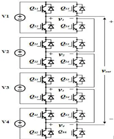
A symmetrical CHB MLI uses 15 H-bridges to generate 31-level output voltage waveform as shown in Figure 1. Thus in this paper, an Asymmetrical CHB MLI making use of 4 H-bridges is considered to generate 31-level output voltage waveform. The values of input voltage DC sources are in ratio V1:V2:V2:V3=1:2:4:8. Hence we can obtain the following relation for Asymmetrical CHB MLI
M=(2Nx2)-1
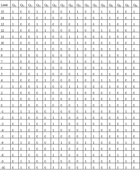
Where, M = number of levels in output voltage waveform & N = number of H-bridges in the circuit. Table 1 shows the switching states to generate 31-level output voltage.
Table 1. Switching table designed for 31-level asymmetrical CHB inverter for source ratio 1:2:4:8
Level Q11 Q12 Q13 Q14 Q21 Q22 Q23 Q24 Q31 Q32 Q33 Q34 Q41 Q42 Q43 Q44
15 1 0 0 1 1 0 0 1 1 0 0 1 1 0 0 1
14 1 0 0 0 1 0 0 1 1 0 0 1 1 0 0 1
13 1 0 0 1 1 0 0 0 1 0 0 1 1 0 0 1
12 1 0 0 0 1 0 0 0 1 0 0 1 1 0 0 1
11 1 0 0 1 1 0 0 1 1 0 0 0 1 0 0 1
10 1 0 0 0 1 0 0 1 1 0 0 0 1 0 0 1
9 1 0 0 1 1 0 0 0 1 0 0 0 1 0 0 1
8 1 0 0 0 1 0 0 0 1 0 0 0 1 0 0 1
7 1 0 0 1 1 0 0 1 1 0 0 1 1 0 0 0
6 1 0 0 0 1 0 0 1 1 0 0 1 1 0 0 0
5 1 0 0 1 1 0 0 0 1 0 0 1 1 0 0 0
4 1 0 0 0 1 0 0 0 1 0 0 1 1 0 0 0
3 1 0 0 1 1 0 0 1 1 0 0 0 1 0 0 0
2 1 0 0 0 1 0 0 1 1 0 0 0 1 0 0 0
1 1 0 0 1 1 0 0 0 1 0 0 0 1 0 0 0
0 1 0 0 0 1 0 0 0 1 0 0 0 1 0 0 0
-1 0 1 1 0 0 1 0 0 0 1 0 0 0 0 1 0
-2 0 1 0 0 0 1 1 0 0 1 0 0 0 0 1 0
-3 0 1 1 0 0 1 1 0 0 1 0 0 0 0 1 0
-4 0 1 0 0 0 1 0 0 0 1 1 0 0 0 1 0
-5 0 1 1 0 0 1 0 0 0 1 1 0 0 0 1 0
-6 0 1 0 0 0 1 1 0 0 1 1 0 0 0 1 0
-7 0 1 1 0 0 1 1 0 0 1 1 0 0 0 1 0
-8 0 1 0 0 0 1 0 0 0 1 0 0 0 1 1 0
-9 0 1 1 0 0 1 0 0 0 1 0 0 0 1 1 0
-11 0 1 1 0 0 1 1 0 0 1 0 0 0 1 1 0
-12 0 1 0 0 0 1 0 0 0 1 1 0 0 1 1 0
-13 0 1 1 0 0 1 0 0 0 1 1 0 0 1 1 0
-14 0 1 0 0 0 1 1 0 0 1 1 0 0 1 1 0
-15 0 1 1 0 0 1 1 0 0 1 1 0 0 1 1 0
III.CONTROL TECHNIQUES FOR MULTILEVEL INVERTER
3.1. Equal Phase Angle Technique
In this technique, the switching angles are equally spaced. Hence, for a particular inverter level required, the width of every level in the output waveform is considered equal.
Let θ1, θ2…….θ15be the switching angles. For 31-level inverter, the conduction period of each level is equal i.e
Δθ=180̊ / 31=5.79̊
Therefore the switching angles are:
θ1=5.79̊; θ2=θ1+5.79̊=11.592̊; θ3=θ2+5.79̊=17.388 θ4=θ3+5.79̊=23.184̊; θ5=28.98̊; θ6=34.77̊; θ7=40.572̊; θ8̊=46.368;
θ9=52.164̊; θ10=57.96̊; θ11=63.756̊; θ12=69.552̊; θ13=75.348̊; θ14=81.144̊; θ15=86.94̊.
3.2. Genetic Algorithm (GA) Technique
This isa soft computingtechnique which applies biological evolution in the optimization process. This method is straightforward & trouble-free because it doesn’t involve any mathematical modeling and initial guess. Hence, this technique can be readily used to evaluate the non-linear equations.Here the purpose of using GA is to find the optimum switching angles such that the objective function value gets minimized so that the THD is reduced. The procedure to apply Genetic Algorithm for optimization is as follows:
1) Initialization of the population: Algorithm is initialized with a population size which gives the number of general solutions(chromosomes). Every switching angle is a Gene.
Here the population size is chosen to be 20 and 15 genes are the switching angles θ1,θ2, θ3,….. θ15 for a 31-level CHB MLI. Initial population is chosen arbitrarily to comply with the constraint which says that the angles have to be in ascending order between 0° to 90°.
2) Evaluation of fitness function: Objective function is associated with a fitness value which gives the measure of the quality of answer. Here objective function is the THD, which is to be minimized for getting better quality of output.
3) Selection: Parents are chosen by the selection rules to generate offspring that produce the next generation. The individuals that are fittest survive and the rest get eliminated.
4) Crossover & Mutation: Genes are interchanged during crossover to reproduce superior offspring. Mutation is a operator in which the changes take place within the same gene. This broadens the search space & avoids the algorithm to fall into local minimum.
5) Stop Criterion: Is the condition in which the algorithm terminates. The algorithm is set to 250 iteration as the stop criterion.
technique etc to find the optimum solution for the equations . In this paper, Genetic Algorithm technique is incorporated for solving the SHEPWM nonlinear equations.
SHE method is illustrated bellow:
The Fourier series expansion of the staircase voltage waveform of multilevel inverter is given as,
( ) = ( sin( ) + cos( ) )………. (1)
Due to quarter symmetry of the waveform, the even harmonics are canceled (bn=0) and only odd harmonics are considered. The value of an is computed from Fourier series factor & only the first quadrant switching angles, α1, α2,
…, αm, is expressed due to symmetry as:
an= (4V /nπ) cos (nα )……….……….. (2)
0< < < <…….. < ……….…….. (3)
For any harmonics, (2) is expressed up to kth term, where ‘m’ is the number of variables corresponding to switching
angles α1 to αm of the first quadrant satisfying equation (3). In selective harmonic elimination, M is designated as
desired value for fundamental component & the other harmonics to be removed are equated to zero as shown in equation (4),(5),(6)
= (4 / ) cos ( ) = M……….………. (4) = (4 /5 ) cos (5 ) = 0……….……….. (5) = (4 /n ) cos (n ) = 0 .……….……. (6)
By solving the above equations using GA MATLAB code, we obtain the optimum switching angles for fixed population size and number of iterations as shown below.
Switching Angles Switching Angles Switching Angles
θ1 2.96° θ6 22.23° θ11 47.60°
θ2 7.26° θ7 27.58° θ12 55.64°
θ3 14.87° θ8 39.38° θ13 61.27°
θ4 16.99° θ9 45.57° θ14 61.79°
θ5 19.27° θ10 47.21° θ15 84.78°
IV.SIMULATION OF PROPOSED CIRCUIT & DICUSSION OF RESULTS
The circuit for 31-level Asymmetrical CHBMultilevel Inverter is developedin MATLAB/Simulink software and simulation studies are conducted using both the techniques.
The output voltage of inverter is fixed as Vorms=230V
Thus, the peak voltage is calculated Vm= √2 * Vorms=√2 * 230=324V
The DC voltage sources are in ratio 1:2:4:8 to generate 31-levels, having magnitudes:
V1 V2 V3 V4 Vm =V1+V2+V3+V4
21.6V 43.2V 86.4V 172.8V 324V
Figure 2 shows the MATLAB/Simulink circuit for Asymmetrical CHB 31-level inverter in which four H-bridges and 16 switching devices (MOSFETs) are used.The pulses are given to switches by connecting pulse generator to the gate terminal of each switch.
Figure 2. MATLAB Simulink circuit for 31-level Asymmetrical CHB inverter
Figure 3 & Figure 4 gives the output voltage waveform and its FFT analysis for load R=25Ω, L=100mH using Equal
Angle and GA technique respectively.nThe simulated results obtained by FFT analysis of output voltage waveform for
load R=25Ω & inductance varying from 20mH to 100mH is tabulated in Table 2 & Table 3 using Equal phase angle
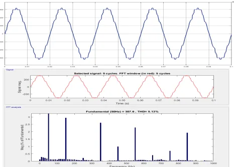
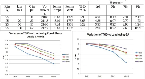
technique and GA respectively. By using Genetic Algorithm technique,particular lower order harmonics can be eliminated. In table 3 we can observe that the 5th harmonic has been eliminated thereby reducing the overall %THD. Alsousing GA the 3rd harmonic is minimizedbecause optimum switching angles are obtained.
Figure 3.Output voltage waveform and FFT analysis with R=25 Ω, L=100mH using Equal angle criteria
Table 2. Results for various parameters obtained for 31-level CHB-MLI using Equal Phase Angle technique Harmonics R in Ω L in mH C in µF Vo rmsVol ts Io rms Amps Po rms Watt THD in %
3rd 5th 7th 9th
25 0 0 187.7 7.5 1408 12.27 10.9 3.7 1.8 1.3
25 20 30 188.4 7.3 1375 11.89 10.7 4 1.6 1.5
25 50 57 190.2 6.4 1217 11.69 10.5 4.3 1.4 1.6
25 100 62 193 4.8 926 11.38 10.1 4.5 1.3 1.5
Table 3. Results for various parameters obtained for 31-level CHB-MLI using GA technique Harmonics R in Ω L in mH C in µF Vo rmsVol ts Io rms Amps Po rms Watt THD in %
3rd 5th 7th 9th
25 0 0 210.8 8.43 1779 6.96 4.76 0.13 2.31 2.13
25 20 30 211.8 8.19 1737 6.68 4.38 0.07 2.70 1.73
25 50 57 214.0 7.24 1551 6.22 3.93 0.22 2.90 1.24
25 100 62 217.7 5.47 1192 5.13 2.94 0.22 2.60 0.99
Figure 5.Variation of THD Vs RLC-Load using Equal Phase Angle criteria & GA respectively
V.CONCLUSION
In this paper a comparative study on performance of 31-level Asymmetrical CHB MLI using Equal Phase Angle Technique and Genetic Algorithm technique is carried out. The simulation for both the techniques is done using MATLAB/ Simulink and the results obtained are presented.
From the obtained results it is clear that the 4 H-bridge Asymmetrical Inverter considered is able to generate 31-level in the output. This topology uses only 16 switches compared to 60 switches in the Symmetrical configuration. The simulation results shows that the THD obtained for load R=25 Ω & L=100mH the THD obtained is 11.38% for Equal Phase Angle technique, where as for GA is 5.13%. Hence it can be concluded that GA is able to generate output voltage waveform having the THD values within the standards defined.
REFERENCES
[1] T. A. Meynard and H. Foch, "Multi-level choppers for high voltage applications," Eur. Power Electron. Drives J., vol. 2, no. I, p. 41, Mar.l
992.
[2] A. Nabae, 1. Takahashi, and H. Akagi, "A new neutralpoint clamped PWM inverter," IEEE Trans. Ind. Applicat., vol. IA-J7, pp. 518-523,
Sept./Oct. 1981.
[3] J. S. Lai and F. Z. Peng, "Multilevel converters-A new breed of power converters," IEEE Trans. Ind. Applicat., vol. 32, pp. 509-517,
May/June. 1996.
[4] L.Nanda, A.Dasgupta, U.K.Rout, “Comparative studies of different topologies of Multilevel Inverter with SIMULINK”, IEEE Conf.,
International Conference on Inventive Systems and Control,ICISC-2017.
[5] Bharti,K.Verma, A.Gupta “A Review on Switching Function of Multi Level Inverter and Applications” , IEEE-2016
[6] Rakshitha R. Prabhu, J. Madhusudhana and P. S. Puttaswamy, “Comparative Study of 31-LevelSymmetrical and AsymmetricalCascaded
H-Bridge Multilevel Inverter,” Springer Nature Singapore Pte Ltd. 2019 V. Sridhar et al. (eds.), Emerging Research in Electronics, Computer Science and Technology, Lecture Notes in Electrical Engineering Vol 545, ICERECT-2018, pp.1185-1197.
[7] J. Madhusudhana, Mohamed Rafiq A. Chapparband, P. S. Puttaswamy, “Design and Development of 15-LevelAsymmetrical Cascaded
MultilevelInverter,”, Springer Nature Singapore Pte Ltd. 2019 V. Sridhar et al. (eds.), Emerging Research in Electronics, Computer Science and Technology, Lecture Notes in Electrical Engineering Vol 545, ICERECT-2018, pp.1169-1183.
[8] T. Bruckner and D. G. Holmes, “Optimal pulse-width modulation forthree-level inverters,” IEEE Trans. Power Electron., vol. 20, no. 1,
pp.82–89, Jan. 2005..
[9] M.Sarvi, M.R.Salimian, “Optimization of specific harmonics in multilevel converters by GA &PSO ”,UPEC2010, 31st Aug- 3rd September .
[10] Madhusudhana J, P S Puttaswamy, SunilKumar, “Geneticalgorithm based 15-level modified multilevel inverter for stand alone photovoltaic
applications,” IJMTER-2016, pp. 355-367
[11] Sarika D Patil ,Sumant G Kadwane,Snehal P Gawande , “Ant colony optimization applied to selective harmonic elimination in multilevel
inverters ,” 2nd International Conference on Applied and Theoretical Computing and Communication Technology (iCATccT),IEEE-2016, pp-637-640.