Design and Simulation of PV Based Fuzzy Logic
controller for the Compensation of Utility
Current Using Active Power Filter for the Non
Linear Load
Puvvula Hemanth Prithvia
1& A.S.S. Veerendra Babu
2PG Scholor1 Assistant Professor2 , Adithya College Of Engineering, JNTU Kakinada
ABSTRACT
The photovoltaic (PV) generation is increasingly popular nowadays, while typical loads require more high-power quality. Basically, one PV generator supplying to nonlinear loads is desired to be integrated with a function as an active power filter (APF). In this paper, a three-phase three-wire system, including a detailed PV generator, dc/dc boost converter to extract maximum radiation power using maximum power point tracking, and dc/ac voltage source converter to act as an APF, is presented. The instantaneous power theory is applied to design the PV-APF controller, which shows reliable performances. The MATLAB/Sim power Systems tool has proved that the combined system can simultaneously inject maximum power from a PV unit and compensate the harmonic current drawn by nonlinear loads.
INTRODUCTION
Power supply and power quality has been critical issues in power system recently. The grid-connected photovoltaic (PV) generator has nowadays become more popular because of its reliable performance and its ability to generate power from clean energy resources [1]–[3]. The dc output voltage of PV arrays is connected to a dc/dc boost converter using a maximum power point tracking (MPPT) controller to maximize
their produced energy [5]. Then, that converter is linked to a dc/ac voltage source converter (VSC) to let the PV system push electric power to the ac utility. The local load of the PV system can specifically be a nonlinear load, such as computers, compact fluorescent lamps, and many other home appliances, that requires distorted currents [4]. Development of a means to compensate the distribution system harmonics is equally urgent. In this case, PV generators should provide the utility with distorted compensation capability, which makes currents injected/absorbed by the utility to be sinusoidal [7]. Therefore, the harmonic compensation function can be realized through flexible control of dc/ac VSC.
Instantaneous power theory has successfully completed active power filter (APF) designing with good performance [8]. However, the PV-APF combination has just been gradually developed for several years [9]. This combination is capable of simultaneously compensating power factor, current imbalance, and current harmonics, and also of injecting the energy generated by PV with low total harmonic distortion (THD). Even when there is no energy available from PV, the combination can still operate to enhance the power quality of the utility. To the best of our knowledge, this idea was initiated in 1996 by
Kim et al. [10]. In this study, the PV system
increase the entire cost. Besides, the mathematical demonstration was not sufficiently provided. After that, the control techniques have been improved in some later efforts to develop PV inverters with real power injection and APF features [11]–[16]. However, their research did not show consistent results obtained by their proposed theories, and they are applicable for a single-phase PV only. The most recent completely released paper in 2013 [17] uses current references as the main functions of the dc/ac controller, which coincides with the basic ideas of this paper. By another manner in this paper, the proposed PV-APF controller utilizing power references shows some significant improvements in theory and a simple control topology. The PV-APF system helps the utility supply a unity power factor and pure sinusoidal currents to the local nonlinear loads by generating the oscillating and imaginary components. When there is an excess power, that PV unit will only inject average power to the utility. As a result, this system can be considered as a distributed APF, which is a better solution than adopting passive filters or centralized APFs [18]. The main contributions of this paper are threefold
1) For the first time, a fully complete PV-APF combination system is presented.
2) The controller based on instantaneous power theory and instantaneous power balance is proposed to replace the conventional dq-current controller for a PV unit. 3) Flexible operation modes of the PV-APF combination system are possible in the proposed model.
The rest of this paper is organized as follows. Section II briefly introduces the implemented PV-APF combination system with the PV modeling technique and the selected MPPT topology. Section III describes the instantaneous power balance among the parts of the system mentioned in Section II. Section IV explains the proposed
controller. Section V evaluates the performance of the proposed method based on simulated test cases in the MATLAB/ Simpower Systems environment. Finally, the conclusion is drawn in Section VI
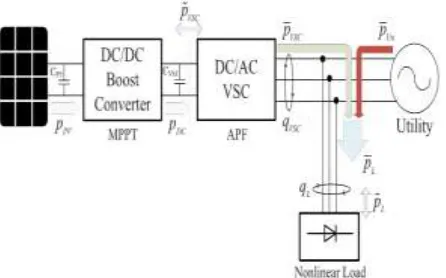
FIGURE1. Proposed design of PV-APF combination .
II.
PV-APF
COMBINATION
SYSTEM
The detailed PV-APF configuration is shown in Fig. 1, which consists of the following.
1) The PV 5series-66parallel array, which is Sun Power SPR-305-type, delivers a maximum of 100-[kW] power at 1000-W/m2 solar irradiance, assuming that there is no battery storage system connected to the dc bus.
2) A 5-kHz boost dc/dc converter implements MPPT by an incremental conductance–integral regulator technique, which automatically varies the duty cycle in order to generate the required voltage to extract maximum power.
3) The dc bus is connected to a two-level three-phase dc/ac VSC with a CVSC capacitor. The dc/ac VSC converts the 500 [V] dc to 260 [V]/60 [Hz] ac supplying to local nonlinear loads and connects to a stiff utility. The dq-current and PV-APF and PV-APF controllers are applied for this dc/ac VSC subsequently.
5) The loads include a three-phase diode rectifier supplying a current of 450 or 50 [A] at dc side and one phase diode rectifier with 50-[A] dc current connecting between phase A and phase B to make an overall unbalanced load.
6) This PV-APF combination system is connected directly to the utility for shunt active filter implementation.
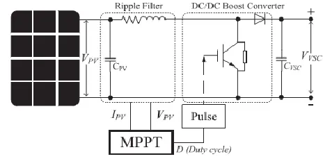
DYNAMIC MODEL OF PV ARRAY
The PV array involves N strings of modules connected in parallel, and each string consists of
M modules connected in series to obtain a suitable power rating. The dynamic model of PV cell is shown in Fig. 2 [3]
FIGURE 2. Equivalent electrical circuit of the PV cell
The output-terminal current I is equal to the light generated current IL, less the diode-current Id and the shunt leakage current (or ground-shunt current) ISh. The series resistance RS represents the internal resistance to the current flow. The shunt resistance RSh is inversely related to leakage current to the ground. In an ideal PV cell,
RS = 0 (no series loss) and RSh = infinite (no leakage to ground). In a typical high-quality 1-in2 silicon cell, RS = 0.05–0.10 [•] and RSh = 200–300 [•]. The PV conversion efficiency is sensitive to small variations in RS, but is insensitive to variations in RSh. A small increase in RS can decrease the PV output significantly. The two most important parameters widely used for describing the cell electrical performance are the open-circuit voltage Voc = Vout + RSI
obtained when the load current is zero (I = 0) and
the short-circuit current Isc. Ignoring the small diode and the ground-leakage currents under zero terminal voltage, the short-circuit current under this condition is the photocurrent IL. The PV modules are modeled approximately as a constant current source regarding the electrical analysis. The basic equation describing the I–V
characteristic of a practical PV cell is
(1)
Where ID is the saturation current of the diode, Q
is the electron charge (1.6 × 10⁻¹⁹ C), A is the curve fitting constant (or diode emission factor),
K is the Boltzmann constant (1.38×10⁻²³ J/◦K),
andT (◦K) is the temperature on absolute scale.
The ISh, that, in practical cells, is smaller than IL
andId, can be ignored. The diode-saturation current can, therefore, be determined experimentally by applying voltage Voc in the dark (IL = 0) and measuring the current entering the cell. This current is often called the dark current or the reverse diode-saturation current Id.
B. MPPT IN DC/DC CONVERTER
FIGURE 3. I–V curve and remarkable points.
The regulator output of MPPT is the duty cycle correction for semiconductor switches. In summary, the controller of the dc/dc boost converter is shown in Fig. 4.
FIGURE 4. Controller mechanism of the boost converter.
III. INSTANTANEOUS POWER
BALANCE
Instantaneous power flow among the parts of the PV-APF system simplified in Fig. 5 is a
compromise between technical constraints and designed targets. The dc/dc boost converter regulates its semiconductor switches to extract the maximum power generated by
FIGURE 5. Instantaneous power flows among the PV-APFsystem.
PV array (pPV). The MPPT methods could be chosen appropriately in any specific circumstance. Beyond that converter with the power output pDC, the dc/ac VSC keeps a significant role in implementing a given control duty. At the dc side, the power concept is consistent. However, at the ac side, the instantaneous power includes both the active part (pVSC) and the imaginary part (qVSC) [8]. The losses at the dc/dc boost converter and the dc/ac VSC are ignored
pPV ≈ pDC ≈ pVSC.
The load demand includes real power and imaginary power. In general, the real and imaginary power include two parts: 1) an average (superscript ¯) one, and 2) an oscillating (superscript ˜) one, which are realized through a low-pass filter (LPF) (or rarely a high-pass filter)
sinusoidal currents from the utility. Consequently, the PV-APF combination has to supply the oscillating components and one part of the average component of both real and imaginary power demand utilizing the PV output power.
In general, there are two cases of utility power flow:
1) PV supplies enough power for local nonlinear loads and injects its excess power to the utility; 2) PV supplies one part of nonlinear loads consuming and the other part of load power is received from the utility.
Real power p is calculated using v, i at ac side which is the same as in dc side VPV × IPV of the PV if no loss while the imaginary power is calculated at ac side only. The average real power
p¯ represents the energy flow per time in one direction only that is effectively converted into work
and, therefore, has to be supplied from the utility if the PV does not provide enough of this power to the load demand, while oscillating real power
p˜ represents oscillating energy
flow per time. q¯ power corresponds to conventional threephase reactive power and does not contribute to transferred power while q˜
power is exchanged among three phases. Since the oscillating components make no contribution to instantaneous or average energy flow and their average value is zero, they should be supplied by the PV-APF combination via the dc/ac VSC. The PV-APF combination has a better advantage that
it also can supply real power compared with a normal APF configuration.
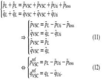
There is an instantaneous power balance among the three parts at the point of common coupling (PCC). If the PV-APF combination can supply undesirable owers to the load, the utility will supply only average part of the real power. Under that circumstance, sinusoidal currents are obtained. The controlling mechanism is to define those undesirable powers from the load and then to make the PV-APF combination generate it. Obviously, the rest of the required power is supplied from the utility. Fig. 5 illustrates case 2, where the utility has to inject one part of active power (pUti) for the load. In this case, the pure fed currents from the utility will be easily realized using an APF function, which means that it provides only the average components. The oscil
latin g com pone nts of the real power and all components of the imaginary power of the load in any status are supplied by the PV-APF combination. The balanced relation among instantaneous powers in Fig. 5 is clarified in the following equations :
The dc/ac VSC modulates real and imaginary power balance among those parts of system.
The dc/ac VSC modulates real and imaginary power balance among those parts of system.
IV. CONTROLLERS FOR DC/AC CONVERTER
conventional way, the dq-current controller is used to inject maximum real power from PV and zero
reactive power to keep unity power factor of the utility. While a nonlinear load is connected close to PV position, the proposed unique PV-APF controller should be used to compensate the harmonics and help transfer the PV power. At night (no irradiance and no battery) or when there is no PV array, the APF controller is switched into the system in order to operate the CVSC capacitor just for an APF purpose.
A. PV-APF CONTROLLER
The dc/ac VSC integrated by an APF function should provide the harmonic elimination and reactive power compensation and simultaneously inject the maximum power generated by PV units. The controller is established based on the instantaneous power theory, where all the parameters are processed instantaneously. The input signals of that controller include utility voltages (vabc), nonlinear load currents (iabcL), output currents of dc/ac VSC (iabcVSC), utility injected currents (iabcUti), and dc-link voltage VVSC (to prevent overcharge dc-link capacitor). Instantaneous power balance at the dc/ac VSC-utility-load connection point makes (regardless of utility flow direction)
Since the target is laid on the load, its consuming power is continuously measured and analyzed. Using the Clarke transformation, the
instantaneous real power (pL) and imaginary power (qL) of the load can be calculated, as shown in the following equations:
In general, the real and imaginary power include two parts: 1) an average (superscript¯ ) one, and 2) an oscillating (superscript ˜ ) one, which are realized through an LPF (or rarely a high-pass filter). The LPF cutoff frequency must be selected carefully as to the inherent dynamics of loads that lead to compensation errors during transients. Unfortunately, the unavoidable time delay of the LPF may degrade the controller performance. In practice, a fifth-order Butterworth LPF with a cutoff frequency between 20 and 100 [Hz] has been used successfully depending on the spectral components in oscillating part that is to be compensated
The average part derives from the fundamental component of nonlinear load current, while the oscillating part results from the harmonics and negative-sequence components. After successful compensation, the imaginary power and the oscillating part of the real power will come from the
dc/ac VSC. The utility, in that case, supplies only one fraction of the average power required from the load.
energy to (from) the dc-link capacitor CVSC in order to keep its voltage around a fixed reference value (VVSCref ). That real power is fed by the utility. Furthermore, the dc-link voltage regulation passes through a PI-controller via the LPF, which filters out the switching harmonics existing in the dc capacitor voltage. Eventually, reference powers are passed to a current references calculation block. These ideas make the following equations:
If the p¯ loss is supplied by the PV unit and the PV-APF combination compensates all imaginary power of load demand, (12) is changed to
After finding out the reference power for dc/ac VSC, using the reverse Clarke transformation, the reference current values in the three phases are generated as seen in the following equations:
Fig. 6 summarizes the complete algorithm of a controller for three-phase three-wire dc/ac VSC that compensates oscillating real power and oscillating imaginary power, and supplies real power of load. The hysteresis control technique is used to switch insulated-gate bipolar transistor gates [19].
B. APF CONTROLLER
This section reminds the topology of well-known APF controllers based on instantaneous power theory. The APF applications mentioned in [7] use this Akagi technique. The utility currents are not measured by this controller. Only the load currents and the output currents of the APF are measured. The greatest difference of this controller compared with the PV-APF controller is the calculated reference values generated from
C VSC, which are oscillating powers as in
In this cas
e, the utility must supply the constant dc-link voltage regulation p¯ loss.
V. SIMULATION VALIDATION
FIGURE 6. Controller topology of dc/ac VSC in the PV-APF combination.
TABLE 1. System parameters in simulation.
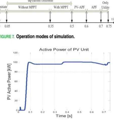
harmonic of nonlinear loads. The main parameters of the system used in the simulation study are indicated in Table 1. The simulation is run in a period of 0.75 s. The important time instances are: 1) at 0.05 s, turn ON MPPT and VSC dq-current controller; 2) at 0.35 s, activate MPPT; 3) at 0.5 s, switch VCS dq-current controller to PV-APF controller; 4) at 0.6 s, switch to APF controller without PV; 5) at 0.7 s, switch PV-VSC out of system; and 6) at 0.75 s, stop simulation. As mentioned, the controller in PV-APF mode requests the PV unit to implement both duties, which are injecting power to the local load and compensating that nonlinear load as well. The APF controller mode requires only
CVSC for the APF purpose when the PV unit
generates zero power. In short, there are four modes of running simulation, as clarified in Fig. 7.
A. PV UNIT PERFORMANCE
The PV power output is shown in Fig. 8. Without the MPPT control when the dc/dc converter uses constant duty cycle, PV power output could not reach maximum
FIGURE 8. Output power of PV during running time
FIGURE 9. Duty cycle and VPV changed by MPPT. (a) Outputvoltage of PV unit. (b) Duty cycle of MPPT.
From 0.6 s, the duty cycle running in PV-APF mode slightly increased to adapt to power dynamic response of compensation. Because the PV unit runs in the conventional dq -currentcontroller until 0.5 s, the power output, including 100-[kW] active power and 0-[kVAr] reactive power, makes the CVSC voltage at a constant value of 500 [V]. During APF mode in [0.6–0.7] s, the PV unit is switched out from the entire system and then the output active power is gradually reduced. In this duration, the nonlinear load is supplied by the utility.
ACTIVE POWER FILTER PERFORMANCE
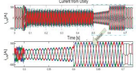
The high load is natural diode rectifiers consuming 450- [A] dc current for three phases and 50-[A] dc current for one phase. Then, the total load power demand is ∼ 130 [kW]. This six-ripple dc current brings higher fifth-order and seventh-fifth-order harmonics. If a three-phase-controlled rectifier load is used, the THDs increase while the commuted angles increase. In this case, both the PV unit and the utility should supply power to the load. The current from the utility is the most important point that should be considered in this paper and it is shown in Fig. 10.
FIGURE 10. Utility supplied current waveform.
higher than the utility currents in the PV-APF mode as seen in Fig. 10. Switching out the PV unit, the utility have to supply the entire loads. From 0 to 0.05 s, during the starting time of simulation, the waveforms of the utility currents look like the load demand current. In addition, from 0.7 to 0.75 s, its waveform is exactly similar to the load current. Both of them have almost rectangular shapes. This is the typical waveform of a three-phase diode rectifier, since the constant dc current is applied at the dc side and commutation interval is considered .
The current and voltage of phase A is superimposed in Fig. 11 to show the effect of the APF controller in modifying power factor. The utility current and voltage are at the same phase, since the PV-APF unit compensated all imaginary powers of load demand showing the effect of the APF controller in modifying power factor.
FIGURE 11. Utility supplied current and PCC voltage waveform.
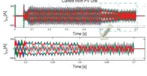
The THD of currents in each mode of operation is analyzed using fast Fourier transform (FFT), as shown in Fig. 12, to make a comparison among those modes and the advantage of the APF function, which is integrated in the PV unit. During dq-current mode, the current from the utility is distorted (THD is 70.05%), since the current from the PV unit is sinusoidal as in Fig. 13.
FIGURE 12. THD in four modes of PV system operation while utility supplies power. (a) dq -current mode. (b) PV-APF mode. (c) APF mode. (d) Only utility supplies load.
FIGURE 13. PV supplied current waveform.
and PV-APF mode, the even-order harmonics appear at higher magnitudes.
As a result, when a PV unit run by conventional dq-current controllers is connected to the utility feeding a nonlinear load, the utility current suffers the highest THD values. Therefore, from the power quality viewpoint, the PV unit should run in the proposed PV-APF mode instead of dq-current mode. In the PV-APF mode, the load consumes a huge amount of power and its configuration significantly impacts the APF performance, or, in other words, a link between the PV-APF unit and the load is tighter and so the utility has to supply its power to the load. That is why the load commutation switching affects the utility current performance.
The instantaneous real power balance (p) among three parts, including the PV unit, the utility, and the local load, is shown in Fig. 14, while those of imaginary power balance (q) are presented in Fig. 15.
FIGURE 14. Real power from the (a) utility, (b) PV unit, and (c) load, while the utility supplies power.
The instantaneous real and imaginary powers are addressed in the following comments.
1) dq-CurrentMode:pUti contains both average
and oscillating components while p PV does the same thing since the dq-current controller in this simulation is affected by nonlinear loads. In general, PV units should inject in only average components. In the same manner, q Uti and qPV have both components.
2) PV-APF Mode: pUti contains only average
component under the proposed controller; pPV also has two components. However, pPV tends to reduce because qPV contains both the components that gradually increase.
FIGURE 15. Imaginary power from the (a) utility, (b) PV unit, and (c) load, while the utility supplies power.
3) APF Mode: pUti and qUti supplies only
average components; the oscillating part of load is fed by CVSC in p˜PV and q˜PV.
4) Utility Mode: pUti and qUti are exactly equal
to the consuming load while the PV unit generates no power.
As the PV-APF controller is designed based on instantaneous power balance, the filtering effect is also feasible in the case that the utility receives power from PV
shows the system response while the local load consumes only 50-[A] dc current for a three-phase rectifier and 50-[A] dc current for a one-phase rectifier. In this case, the utility receives power from the PV units instead of supplying currents to that local load as in the cases mentioned above.
FIGURE 16. Utility received current waveform.
In PV-APF mode and APF mode, the utility currents are sinusoidal using those controllers. The THD of currents in each mode of operation is analyzed using FFT, as shown in Fig. 17, to make a comparison between those modes and the advantage of the APF function integrated in the PV unit
FIGURE 17. THD in four modes of PV system operation while utility receives power. (a) dq-current mode. (b) PV-APF mode. (c) APF mode. (d) Only utility supplies load.
During dq-current mode, the current from the utility is distorted (THD is 30.9%), since the current from the PV unit is sinusoidal, as explained previously. In PV-APF mode, when the PV unit generates normal power and filters out harmonics as well, the THD is relatively small (3.67%). In the APF mode when the PV unit generates zero power and CVSC is utilized, the THD is also small (6.76%). As stated before, the PV unit should run in the proposed PV-APF mode instead of dq-current mode. Since the load power is low, the utility plays a significant role in power balancing, and the THD level during PV-APF
mode is reduced in this case.
In this case, the instantaneous real power balance (p) among three parts, including the PV unit, the utility, and the local load, is shown in Fig. 18. The real power from the utility has a minus sign. The PV unit generates ∼100 [kW] in which 50 [kW] is
consumed by the load and 50 [kW]
is supplied to the utility. As stated previously, the utility real power during APF mode and PV-APF mode contains average components. The oscillating parts of real power consuming are provided by dc/ac VSC instead. In addition, the imaginary power balance (q) is presented in Fig. 19. The PV unit supplies all imaginary components during PV mode and PV-APF mode to let zero imaginary power come to the utility.
FIGURE 19. Imaginary power from the (a) utility, (b) PV unit, and (c) load, while the utility receives power.
CONCLUSION
Regarding the multifunctional DG concept, in this paper, a dynamic grid-connected PV unit is built and the PV-APF combination system with a local controller is proposed. The controller implements two purposes, which are supplying power from the PV unit and filtering the harmonics of the local nonlinear load. The new controller based on instantaneous power balance has been explained accordingly. The MATLAB/SimpowerSystems simulation shows good performances of this controller. The positive influence of MPPT on maximizing PV power output is also validated. The switching among three controllers to dc/ac VSC brings different current waveforms. As a result, the conventional
dq-current controller should not be applied when PV is connected to a local nonlinear load regarding power-quality viewpoint. Preferably, the PV-APF controller compensates the utility currents successfully. While a PV unit is deactivated, the APF function can still operate. It is, therefore, technically feasible for these power electronics-interfaced DG units to actively regulate the power quality of the distribution system as an ancillary service, which will certainly make those DG units more competitive.
REFERENCES
[1] L. Hassaine, E. Olias, J. Quintero, and M. Haddadi, ‘‘Digital power factor control and reactive power regulation for grid-connected photovoltaic inverter,’’ Renewable Energy, vol. 34, no. 1, pp. 315–321, 2009.
[2] N. Hamrouni, M. Jraidi, and A. Cherif, ‘‘New control strategy for 2-stage grid-connected photovoltaic power system,’’ Renewable Energy, vol. 33, no. 10, pp. 2212–2221, 2008.
[3] M. G. Villalva, J. R. Gazoli, and E. R. Filho, ‘‘Comprehensive approach to modeling and simulation of photovoltaic arrays,’’ IEEE Trans.
Power Electron., vol. 24, no. 5, pp. 1198–1208,
May 2009.
[4] N. R. Watson, T. L. Scott, and S. Hirsch, ‘‘Implications for distribution networks of high penetration of compact fluorescent lamps,’’ IEEE
Trans. Power Del., vol. 24, no. 3, pp. 1521–1528,
Jul. 2009.
[5] I. Houssamo, F. Locment, and M. Sechilariu, ‘‘Experimental analysis of impact of MPPT methods on energy efficiency for photovoltaic power systems,’’ Int. J. Elect. Power Energy
Syst., vol. 46, pp. 98–107, Mar. 2013.
[6] M. A. G. de Brito, L. P. Sampaio, G. Luigi, G. A. e Melo, and C. A. Canesin, ‘‘Comparative analysis of MPPT techniques for PV applications,’’ in Proc. Int. Conf. Clean Elect.
Power (ICCEP), Jun. 2011, pp. 99–104.
[7] M. El-Habrouk, M. K. Darwish, and P. Mehta, ‘‘Active power filters: A review,’’ Proc. IEE –
Elect. Power Appl., vol. 147, no. 5, pp. 403–413,
Sep. 2000.
Power Electron., Tokyo, Japan, 1983, pp. 1375– 1386.
[9] Y. W. Li and J. He, ‘‘Distribution system harmonic compensation methods: An overview of DG-interfacing inverters,’’ IEEE Ind. Electron. Mag., vol. 8, no. 4, pp. 18–31, Dec. 2014.
[10] S. Kim, G. Yoo, and J. Song, ‘‘A bifunctional utility connected photovoltaic system with power factor correction and UPS facility,’’
in Proc. Conf. Rec. 25th IEEE Photovolt.
Specialists Conf., May 1996, pp. 1363–1368.
[11] Y. Komatsu, ‘‘Application of the extension pq theory to a mains-couple d photovoltaic system,’’ in Proc. Power Convers. Conf. (PCC), vol. 2. Osaka, Japan, 2002, pp. 816–821.
[12] L. Cheng, R. Cheung, and K. H. Leung, ‘‘Advanced photovoltaic inverter with additional active power line conditioning capability,’’ in
Proc. IEEE Power Electron. Specialists Conf.,
vol. 1. Jun. 1997, pp. 279–283.
[13] T.-F. Wu, C.-L. Shen, C.-H. Chang, and J. Chiu, ‘‘1φ grid-connection PV power inverter with partial active power filter,’’ IEEE Trans.
Aerosp. Electron. Syst., vol. 39, no. 2, pp. 635–
646, Apr. 2003.
[14] H. Calleja and H. Jimenez, ‘‘Performance of a grid connected PV system used as active filter,’’
Energy Convers. Manag., vol. 45, nos. 15–16, pp.
2417–2428, 2004.
[15] X. Chen, Q. Fu, S. Yu, and L. Zhou, ‘‘Unified control of photovoltaic gridconnection and power quality managements,’’ in Proc. Workshop Power Electron. Intell. Transp. Syst.
(PEITS), Aug. 2008, pp. 360–365.
[16] S. Y. Mosazadeh, S. H. Fathi, M. Hajizadeh, and A. R. Sheykholeslami, ‘‘Adaptive hysteresis