ISSN (Print) : 2320 – 3765 ISSN (Online): 2278 – 8875
I
nternational
J
ournal of
A
dvanced
R
esearch in
E
lectrical,
E
lectronics and
I
nstrumentation
E
ngineering
(A High Impact Factor, Monthly, Peer Reviewed Journal)
Website: www.ijareeie.com
Vol. 6, Issue 10, October 2017
Digital Simulation of Closed Loop Controlled
Micro Grid System with Four Different
Sources
R.Bharathidasan, Dr.Prakash
PG Scholar, Dept. of EEE, Bharath University, Chennai, India
Asst. Professor, Dept. of EEE, Bharath University, Chennai, India
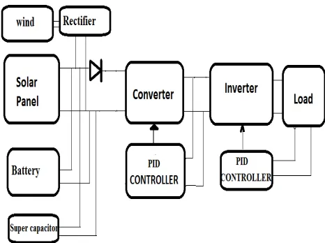
ABSTRACT: Interleaved boost converter is a good interface between four different source and inverter. This Work deals with design, modelling and simulation of the interleaved boost converter inverter based PID controlled four different source systems. Interleaved boost converters to reduce the ripple in the DC output. The DC from the solar cell is stepped up using interleaved boost converter. The output of the interleaved boost converter is converted to 50Hz AC using a single phase full bridge inverter. The objective of this work is to improve dynamic response of closed loop system using PID controller. The simulation results of PI and PID controlled closed loop systems are compared. This paper has presented a simulink model for the closed loop controlled four different source systems.
KEYWORDS: Bidirectional inverter, Interleaved Boost Converter, Maximum power point trackers (MPPTs), Proportional integral derivative (PID), Proportional Controller (PI), Pulse Width Modulation (PWM), DC-distribution applications, Sim Power System.
List of Abbreviations:
ILBC – Interleaved Boost Converter PID – Proportional integral derivative ZVS - Zero Voltage Switch
PWM - Pulse Width Modulation PV - Photo voltaics
WG- Wind generation SC- Supper capacitor BS- Battery source
MPPT- Maximum Power Point Tracker MATLAB- Matrix Laboratory
I. INTRODUCTION
ISSN (Print) : 2320 – 3765 ISSN (Online): 2278 – 8875
I
nternational
J
ournal of
A
dvanced
R
esearch in
E
lectrical,
E
lectronics and
I
nstrumentation
E
ngineering
(A High Impact Factor, Monthly, Peer Reviewed Journal)
Website: www.ijareeie.com
Vol. 6, Issue 10, October 2017
and control scheme. However, it presents the disadvantage of higher number of components and, consequently, low power density and high cost. On the other hand, multiple-port or multiple-input converters (MIC) have recently been introduced and have attracted increased research interest. In these topologies, the common characteristic is the shared output stage by the different input ports, reducing the cost by reducing the number of components, and increasing the system efficiency and power density. However, the control and power management system tend to become more complex. Some of the proposed MIC does not allow bidirectional operation as the input ports are completely decoupled, and therefore they PID be used in systems requiring of energy storage units.
Systems interconnecting a renewable energy source and an energy storage unit are usually known as dual-input converters or three-port converters. In such a system, the mismatch power is handled by the energy storage unit, which will absorb the surplus energy at light load and will supply the energy deficit at heavy load conditions. Therefore, different power flows can take place depending on the power of the renewable energy source and load consumption.
Four Quadrants Integrated Transformers for Dual Input Isolated dc converters is given by Z. Ouyang (2012). Full-Bridge Three-Port Converters with Wide Input Voltage Range for Renewable Power Systems is given by (2012). Interleaved Boost-Half-Bridge Dual-Input DC-DC Converter with a PWM Plus Phase-Shift Control for Fuel Cell Applications is given by Z. Zhang (2013). Multiport Converters Based on Integration of Full-Bridge and Bidirectional DC–DC Topologies for Renewable Generation Systems is given by H. Wu (2014). Dual-Input DC-DC Converter Combining a Boost-Half-Bridge Cell and a Voltage-Fed Full-Bridge is given by Z. Zhang ( 2013). Buck boost dc–dc converter topology with soft switching is given by M. Pavlovsky (2013). A Novel Capacitor-Switched Regenerative Snubber for DC / DC Boost Converters is given by J. Bauman (2011). High- efficiency two- switch tri-state buck-boost power factor correction converter with fast dynamic response and low inductor current ripple is given by M. He (2013). A dual full- bridge resonant class-e bidirectional dc-dc converter is given by S. Jalbrzykowski (2011). Single-inductor dual-output Buck boost power factor correction converter is given by X. Liu (2015). A novel buck-boost converter Combining KY and Buck converters is given by K. I. Hwu (2012). A high-efficiency positive buck boost converter with mode select circuit and feed-forward techniques is given by J.-J. Chen (2103). A Review of Power Decoupling Techniques for Microinverters with Three Different Decoupling Capacitor Locations in PV Systems is given by H. Hu (2013).
The above literature does not cover comparison of PI and PID based closed loop controlled Interleaved boost converter inverter based systems. This work aims to develop closed loop simulink model for ILBC inverter based solar system employing the PID. The PID is proposed for the control of ILBC based wind, battery, supper capacitor & solar system. The Photovoltaic system Using PID is shown in Fig. 1. The output of PV system stepped up using ILBC. The
ISSN (Print) : 2320 – 3765 ISSN (Online): 2278 – 8875
I
nternational
J
ournal of
A
dvanced
R
esearch in
E
lectrical,
E
lectronics and
I
nstrumentation
E
ngineering
(A High Impact Factor, Monthly, Peer Reviewed Journal)
Website: www.ijareeie.com
Vol. 6, Issue 10, October 2017
Fig.2. Circuit of ILBC
II. SIMULATION RESULTS
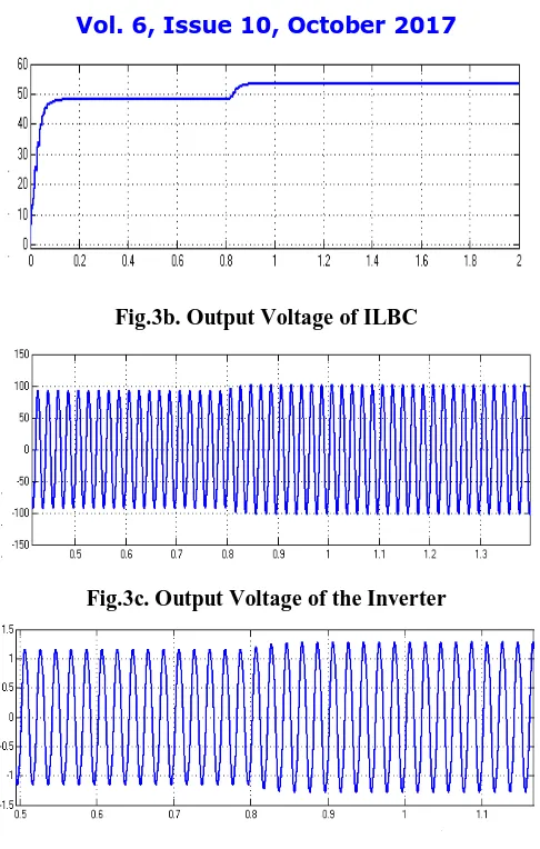
Open loop system with step change in input is shown in Fig. 3. The step change in input due to increase in the wind generation voltage is shown in Fig. 3a. The output voltage of ILBC is shown in Fig. 3b. The voltage increases from 56V to 96V. The AC output voltage and load current are shown in Fig. 3c and Fig. 3d respectively. It can be seen that the steady state errors in the output voltage and current are higher.
Fig.3. Open loop Controlled system with step change in Input
ISSN (Print) : 2320 – 3765 ISSN (Online): 2278 – 8875
I
nternational
J
ournal of
A
dvanced
R
esearch in
E
lectrical,
E
lectronics and
I
nstrumentation
E
ngineering
(A High Impact Factor, Monthly, Peer Reviewed Journal)
Website: www.ijareeie.com
Vol. 6, Issue 10, October 2017
Fig.3b. Output Voltage of ILBC
Fig.3c. Output Voltage of the Inverter
Fig.3d. Output Current of the Inverter
ISSN (Print) : 2320 – 3765 ISSN (Online): 2278 – 8875
I
nternational
J
ournal of
A
dvanced
R
esearch in
E
lectrical,
E
lectronics and
I
nstrumentation
E
ngineering
(A High Impact Factor, Monthly, Peer Reviewed Journal)
Website: www.ijareeie.com
Vol. 6, Issue 10, October 2017
Fig.4. Simulink Model of the Closed Loop System with PI Controller
Fig.4a. Input Voltage of the wind generation System
Fig.4b. Output Voltage of the ILBC
ISSN (Print) : 2320 – 3765 ISSN (Online): 2278 – 8875
I
nternational
J
ournal of
A
dvanced
R
esearch in
E
lectrical,
E
lectronics and
I
nstrumentation
E
ngineering
(A High Impact Factor, Monthly, Peer Reviewed Journal)
Website: www.ijareeie.com
Vol. 6, Issue 10, October 2017
Fig.4d. Output Current of the Inverter
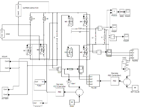
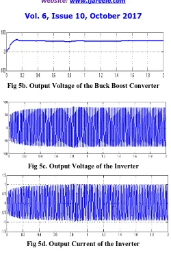
Closed loop system with the PID is shown in Fig 5.The PI controller is replaced by the PID. The inputs to the PID are the error and its derivative. The increase in input due to increase in insulation is shown in Fig 5a. The input voltage increases from 48V to 56V. The output of the ILBC is shown in Fig 5b. The output voltage and current of the inverter are shown in Fig 5c and Fig 5d respectively. The comparison of responses between PI and PID is given in Table – I. The settling time and steady state error are very much reduced using PID.
Fig 5. Simulink Model of the closed loop System with PID
ISSN (Print) : 2320 – 3765 ISSN (Online): 2278 – 8875
I
nternational
J
ournal of
A
dvanced
R
esearch in
E
lectrical,
E
lectronics and
I
nstrumentation
E
ngineering
(A High Impact Factor, Monthly, Peer Reviewed Journal)
Website: www.ijareeie.com
Vol. 6, Issue 10, October 2017
Fig 5b. Output Voltage of the Buck Boost Converter
Fig 5c. Output Voltage of the Inverter
Fig 5d. Output Current of the Inverter
Table – I
Comparison of responses with PI and PID Controllers Controllers Rise
time (s)
Peak time (s)
Settling time (s)
Steady state error (v)
PI controller
0.2 0.21 1.1 5
PID 0.17 0.15 0.9 3.1
III. CONCLUSION
ISSN (Print) : 2320 – 3765 ISSN (Online): 2278 – 8875
I
nternational
J
ournal of
A
dvanced
R
esearch in
E
lectrical,
E
lectronics and
I
nstrumentation
E
ngineering
(A High Impact Factor, Monthly, Peer Reviewed Journal)
Website: www.ijareeie.com
Vol. 6, Issue 10, October 2017
like improved response and reduced steady state error. The disadvantage of this system was that it had limited voltage tracking range.
The scope of this work is the simulation of closed loop controlled converter – inverter system with PI and PID controllers. The closed loop simulation using Fuzzy logic based controller will be done in future.
IV. ACKNOWLEDGEMENT
The authors would like to acknowledge the HOD & Vice Chancellor, Bharath University for providing the facilities to conduct simulation studies.
REFERENCES
[1] Z. Ouyang, Z. Zhang, M. Andersen and O. Thomsen, "Four Quadrants Integrated Transformers for Dual Input Isolated dc dc converters," IEEE Transactions on Power Electronics, vol. 27, no. 6, pp. 2697-2702, 2012.
[2] H. Wu, K. Sun, R. Chen, H. Hu and Y. Xing, "Full-Bridge Three-Port Converters With Wide Input Voltage Range for Renewable Power Systems," IEEE Transactions on Power Electronics, vol. 27, no. 9, pp. 3965-3974, 2012.
[3] Z. Zhang and M. Andersen, "Interleaved Boost-Half-Bridge Dual-Input DC-DC Converter with a PWM Plus Phase-Shift Control for Fuel Cell Applications," in 39th PIDual Conference of the IEEE IndustrialElectronics Society, IECON 2013, 2013.
[4] H. Wu, P. Xu, H. Hu, Z. Zhou and Y. Xing, "Multiport Converters Based on Integration of Full-Bridge and Bidirectional DC–DC Topologies for Renewable Generation Systems," IEEE Transactions on IndustrialElectronics, vol. 61, no. 2, pp. 856-869, 2014.
[5] Z. Zhang, O. Thomsen and M. Andersen, "Soft-Switched Dual-Input DC-DC Converter Combining a Boost-Half-Bridge Cell and a Voltage-Fed Full-Bridge Cell," IEEE Transactions on Power Electronics, vol. 28, no. 11, pp. 4897-4902, 2013.
[6 ] M. Pavlovsky, G. Guidi, and A. Kawamura, “Buck boost dc–dc converter topology with soft switching in whole operating region,”IEEE Trans. Power Electron., vol. PP, no. 99, p. 1, 2013. DOI:10.1109/ TPEL.2013.2258358.
[7] J. Bauman, M. Kazerani, and S. Member, “A Novel Capacitor-Switched Regenerative Snubber for DC / DC Boost Converters,” IEEE, Trans. Ind.Electron., vol. 58, no. 2, pp. 514–523, 2011.
[8] M. He, F. Zhang, J. Xu, P. Yang, and T. Yan, “High- efficiency two- switch tri-state buck-boost power factor correction converter with fast dynamic response and low- inductor current ripple,” IET Power Electron., vol. 6, no. 8, pp. 1544–1554, Sep. 2013.
[9] S. Jalbrzykowski, A. Bogdan, and T. Citko, “A dual full- bridge resonant class-e bidirectional dc-dc converter,” IEEE Trans. Ind. Electron., vol. 58, no. 9, pp. 3879– 3883, Sep. 2011.
[10] X. Liu, J. Xu, Z. Chen, and N. Wang, “Single-inductor dual-output Buckboost power factor correction converter,” IEEE Trans. Ind. Electron.,vol. 62, no. 2, pp. 943–952, Feb. 2015.
[11] K. I. Hwu and T. J. Peng, “A novel buck-boost converter Combining KY and Buck converters,” IEEE Trans. Power Electron., vol. 27, no. 5 pp. 2236–2241, May 2012.
[12] J.-J. Chen, P.-N. Shen, and Y.-S. Hwang, “A high-efficiency positive buck boost converter with mode select circuit and feed-forward techniques,” IEEE Trans. Power Electron., vol. 28, no. 9, pp. 4240– 4247, Sep. 2013.