Power System Based Simulation Study of
UPFC in a Single Transmission Line System
K.N.Babu
1, Deepika M
1, Jaishri D
1, Prasad R R
1, Jisma M
2UG Student, Dept. of EEE, Amrita University, Coimbatore, Tamilnadu, India1
Assistant Professor, Dept. of EEE, Amrita University, Coimbatore, Tamilnadu, India2
ABSTRACT: As the complexity of the power system increases the necessity for carefully designed devices becomes a requirement to monitor and control the changes in the transmission line power flow. Unified Power Flow Controller (UPFC) is used in regulating the transmission line power flow by controlling impedance, voltage magnitude and phase angle. The working region of UPFC forms a locus within which it could be operated at any point to control the power flow in the system. This paper discusses the concept of operation of UPFC based on the above mentioned techniques distinctively. The locus of operation of UPFC is found to understand the region of operation for the connected load. The simulations are performed in MATLAB Simulink.
KEYWORDS: UPFC, locus, MATLAB, power flow, Simulink model.
I.INTRODUCTION
UPFC is a device devised for static and dynamic compensation with real time control on the power system. It can be used to solve various problems faced in the power transmission because of its multifunctional flexibility. The main advantage of UPFC is its access over the power flow parameters in real time and thereby control the real and reactive power independently. The functioning of UPFC can be studied as combined effect of a Static Synchronous Series Compensator (SSSC) placed in series with the transmission line which can control the real and reactive power transmitted and a Static Synchronous Compensator (STATCOM) placed in parallel with the transmission line which can control the bus voltage by injecting reactive power. The combined effect of both these Flexible AC Transmission System (FACTS) devices is achieved because UPFC can control the power flow parameters individually and simultaneously.
This paper presents the simulation of UPFC as a power system device that is, as a voltage source capable of generating power at a specified voltage (V) and required load angle (). UPFC is capable of performing the conventional control capabilities like voltage regulation, line impedance compensation and phase angle regulation. Every single control had been simulated, analysed, studied and the combination effect with the locus was obtained.
II.UNIFIED POWER FLOW CONTROLLER
The FACTS device UPFC was introduced by Gyugyi in 1991 [1]. Figure 1 shows the representation of the structure of UPFC. It consists of two back to back converters operated with a common DC-link. The link allows bidirectional power flow through the series connected Static Synchronous Series Compensator (SSSC) and the shunt connected Static Synchronous Compensator (STATCOM). This allows controlled real and reactive power exchange thus providing series compensation with no external source requirement. The shunt converter supplies the active power demand of the series connected converter. This power is transfer through the DC-link. Also, shunt compensation is possible if the shunt converter is allowed to operate independently. Series converter offers the necessary compensation required for voltage regulation by injecting voltage at an appropriate magnitude and phase angle. The effect of UPFC was explained as a combination of series and shunt compensation by N.G.Hingorani in 1993 [2] and the locus of operation was also determined. In 2011, S.IzadpanahTous, and M. Gorji [4] explained the various modes of operating UPFC. One possible type of modelling a UPFC was done by A. J. F. keri [7] in 1999.
Fig 1. Structure of UPFC Fig 2. UPFC Electric Circuit
III. SIMULATION MODEL
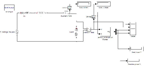
Figure 3 shows the two bus single transmission line model used for the power system based simulation where the power flow parameters can be varied if a FACTS device is introduced.
Fig 3. Single Transmission system model for UPFC study
IV.SIMULATION MODEL PARAMETERS
The values of the each device used in the above simulation model is shown in Table 1. With the assumption of the above parameters, the working of the UPFC is studied by injecting required voltage at specific load angles.
Generator Voltage 22KV, 50Hz
Generator impedance 1+j0.314 Ω
Transmission line impedance j9.424 Ω
Series injection transformer 1:1 ratio, Nominal voltage: 22KV
Load impedance 25+j7.854 Ω
V. NORMAL OPERATING CONDITION (Without UPFC)
The readings in Table 2 present the values of the power system parameters when operating in normal condition without any faults, overloading or compensation from any Flexible AC Transmission System (FACTS) devices.
Load Voltage 19720V, 50Hz
Load Current 788.8 A
Real power transferred 1.555 x 10⁷ W
Reactive power transferred 1.995 x 10⁵ Var
Table 2. Normal operating parameters of the single transmission system
VI. CONTROL CAPABILITIES OF UPFC
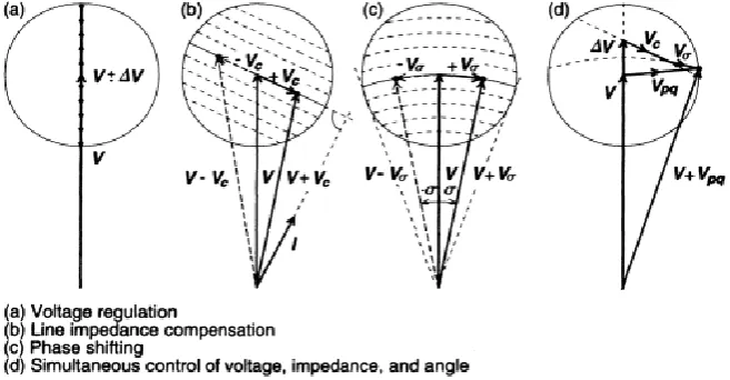
UPFC has the feature of fulfilling all the functions achieved in conventional power transmission system thereby meet multiple control objectives. Figure 4 shows the various transmission control capabilities of UPFC.
VII.CONCEPTUAL STUDY ON UPFC
VOLTAGE REGULATION
UPFC can be used to regulate the voltage level of the buses by injecting voltage in phase with the generated voltage that is, the voltage generated from the generator/grid. Voltage regulation is mainly incorporated when overloading of any buses in the power system network causes reduction in the bus voltage levels. To restore the voltage and the stability of the system, the required ceiling of the bus voltage to be achieved is calculated and the difference of it with the stable voltage level is injected in phase with addition to the existing load angle () of the specific bus.
Calculations:
Initially,
Finally, after injecting voltage of 0.1p.u in series with the sending end.
P = VI sin => sin = 1.882 x 10⁷ / (22000 x 867.6) = 0.986 => = 80.40 - (2) Thus this proves that power transfer can be improved and the voltage level can be brought back to stable condition by injecting a voltage in phase to the sending end voltage. Here the maximum permissible value of injection is 0.1 p.u and this results in an increase of 1.97KV in the receiving end.
Table 3 shows the abnormal operating condition considering the voltage dip in receiving bus has violated the nominal bus voltage.
Parameters Without UPFC With UPFC
Load Voltage 19720V, 50Hz 21690V, 50Hz
Load Current 788.8 A 867.6 A
Real power transferred 1.555 x 10⁷ W 1.882 x 10⁷ W
Reactive power transferred 1.995 x 10⁵ Var 2.356 x 10⁵ Var
Table 3: Voltage regulation
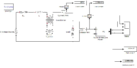
Figure 5 shows the power system based implementation of voltage regulation using UPFC. Thus addition of UPFC helps to improve the voltage and power flow levels.
Fig 5. UPFC – Voltage Regulation
LINE IMPEDANCE COMPENSATION
UPFC can be used in compensate the line impedance. If the power is transferred from the sending end bus to receiving end through a long transmission line it causes significant power loss and voltage drop because of the resistance and reactance present in the transmission line. To reduce this losses and voltage sag, UPFC can be used. By calculating the angle difference between the voltage and current waveforms the phase shift produced due to the transmission line reactance are obtained. Thus a suitable voltage is injected to partially nullify the reactance. This is done by injecting the specific voltage at an angle which is 90 plus angle between voltage and current. When such a voltage is introduced it acts like a capacitance effect partially nullifying the impedance effect on the transmission line.
Calculations:
From figure 4b, the value of Vc must be injected 90 + (the angle created between V and I because of the impedance)
Angle between Voltage and current = 1 + j0.314 + j9.424 + 25 + j7.854 = 26 + j17.592 Ω - (3)
Voltage injected must be cancelling out this impedance effect => = tan-1 (17.592/26) = 34.08(lagging) - (4)
Parameters Without UPFC With UPFC
Load Voltage 19720V, 50Hz 20890V, 50Hz
Load Current 788.8 A 835.5 A
Real power generated 1.618 x 10⁷ W 1.76 x 10⁷ W
Real power transferred 1.555 x 10⁷ W 1.745 x 10⁷ W
Reactive power generated 6.274 x 10⁶ Var 5.289 x 10⁶ Var
Reactive power transferred 1.995 x 10⁵ Var 2.193 x 10⁵ Var
Table 4: Line impedance compensation
Table 4 gives the comparison of all power flow parameters when UPFC is used for line impedance compensation. Figure 6 shows the power system based implementation of line impedance compensation using UPFC.
Fig 6. UPFC – Impedance compensation
PHASE SHIFTING
UPFC also serves the purpose as a controllable phase shifting power electronic system. By exactly determining the phase angle at which the system needs to operated, the value of reactive power flow can be controlled within proper ceiling and floor values. The calculation is done by calculating the present load angle of the system and finding the voltage to be injected to achieve the aimed load angle in the system. Here the magnitude of the supply voltage will not change rather the phase angle of the supple side bus will reach a new value. This method is used to supply the reactive power involved with the transmission angle control by internal Var generation.
Calculations:
Here the value of injected voltage is chosen in such a way that it does not change the magnitude of Vs rather it just
alters the load angle of the sending end bus voltage. Thus the reactive power required for compensation is generated since the generated voltage is in quadrature with the source voltage. We can observe from Table 5 that the sending end voltage has a very minimal change but the reactive power generated from the supply side is significantly reduced when UPFC is used. The voltage injected is 0.03p.u at 90 with respect to Vs as this value changes only the phase angle of the
Parameters Without UPFC With UPFC
Load Voltage 19720V, 50Hz 19730V, 50Hz
Load Current 788.8 A 789.1 A
Real power generated 1.618 x 10⁷ W 1.636 x 10⁷ W
Real power transferred 1.555 x 10⁷ W 1.557 x 10⁷ W
Reactive power generated 6.274 x 10⁶ Var 5.789 x 10⁶ Var
Reactive power transferred 1.995 x 10⁵ Var 1.956 x 10⁵ Var
Table 5: Phase shifting
Table 5 gives the comparison of all power flow parameters when UPFC is used for phase shifting. Figure 7 shows the power system based implementation of line impedance compensation using UPFC.
Fig 7. UPFC – Phase shifting
MULTIFUNCTIONAL POWER FLOW CONTROL
The controls which were discussed above are independent control over the power flow parameters of the system. The major advantage of UPFC over all other Flexible AC Transmission System (FACTS) device is its characteristic of controlling more than one power flow parameters simultaneously. Multifunctional control is executed by simultaneous terminal voltage, series capacitive line compensation and phase shifting as shown in figure 4d. This functional capability is unique to UPFC and thus allows to control real and reactive power individually.
Calculations:
VINJ=V+VC+V=0.1+0.155.92+0.0390=0.19235.869
But the maximum value of voltage injection allowed is considered for a FACTS device as 0.1p.u. Thus the voltage is injected at a magnitude of 0.1 and the same angle as calculated. Thus for a UPFC the net effect can be combined and the real and reactive power flow can be calculated from (6)
- (6)
Parameters Without UPFC With UPFC
Load Voltage 19720V, 50Hz 21350V, 50Hz
Load Current 788.8 A 853.9 A
Real power generated 1.618 x 10⁷ W 1.785 x 10⁷ W
Real power transferred 1.555 x 10⁷ W 1.823 x 10⁷ W
Reactive power generated 6.274 x 10⁶ Var 5.835 x 10⁶ Var
Reactive power transferred 1.995 x 10⁵ Var 2.291 x 10⁵ Var
Table 6: Multifunctional control
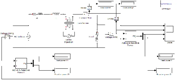
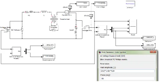
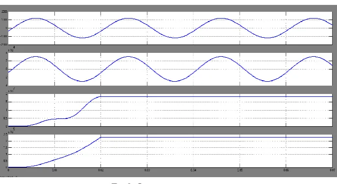
Figure 8 shows the power system based implementation of multifunctional control using UPFC and Figure 9 shows the waveforms of load voltage, load current, real and reactive power transferred.
FIG 8.UPFC–MULTIFUNCTIONAL CONTROL
FIG 9.OUTPUT WAVEFORMS
FIG 10.LOCUSOFOPERATIONOFUPFC
VI.CONCLUSION
The power system based study on Unified Power Flow Controller show that this FACTS device is highly effective when implemented in the modern day power system network. The values in Table 6 gives the idea of overall control and access of all the P, Q, V, parameter by UPFC. The reactive power generated can also be minimized by reducing the transmission line losses. Also the results shows that introduction injection with a maximum of 0.1p.u can only partially reduce the transmission line losses. In order to improve the system efficiency there is also need to use capacitor banks and other condensers working parallely. Thus it proves that UPFC can be used for dynamic power stability during fault and overloading conditions where power can controlled within determined boundaries and also power rerouting, voltage stability can be maintained with the introduction of UPFC in power system network.
REFERENCES
[1] L. Gyugyi, “A Unified Power Flow Control Concept for Flexible AC Transmission Systems”, IEE Proceedings-C, vol. 139, no. 4, pp.
323-331, July 1992.
[2] N. G. Hingorani, “Flexible AC Transmission”, IEEE Spectrum, vol. 30, no. 4, pp. 40-45, April 1993.
[3] N. Dizdarevic, “Unified Power Flow Controller in alleviation of voltage stability problem”, Ph.D. thesis, University of Zagreb, Faculty of Electrical Engineering and Computing, Dept. Power Systems, October 2001.
[4] S. IzadpanahTous, and M. Gorji, “Unified Power Flow Controller and its working modes”, Presented at 2011 World Congress on Engineering
and Technology, China, 2011.
[5] E. M. Saied, and M. A. EL-Shibini, “Fast reliable unified power flow controller (UPFC) algorithm Steady-state and Dynamic Models of
Unified Power Flow Controller (UPFC) for Power System Studies”, Seventh International Conference on AC-DC Power Transmission, 2001,
pp. 321-326.
[6] L Gyugyi and C D Schauder, The Unified Power Flow Controller: A New Approach to Power Transmission Control.„ IEEE Transactions on
Power Delivery, vol 10, no 2, April 1995, p 1085.
[7] A. J. F. keri, A. S. Mehraban, X. Lombard, A. Eiriachy, and A. A. Edris, “Unified power flow controller (UPFC): modeling and analysis”,