964 | P a g e
SHUNT ACTIVE POWER FILTER WITH 3 LEVEL 4
LEG FCC FOR POWER QUALITY IMPROVEMENT
Prof.K.ChandraObula Reddy
1, Miss. Gayatri G.Pannam
2Assistant professor1, PG Student [EPS]2
1,2
Dept. of EE, MSS’S CET, Jalna, Maharashtra, (India)
ABSTRACT
This paper presents the various causes of poor power quality, their effects and solutions are proposed with
respect to present nonlinear load patterns of the power system. It also presents the new implementation of the
system ,which includes shunt active power filter with three level four leg flying capacitor converter which is
solution for compensating current into the distribution line by using residual current, The three main issues
regarding the algorithm development are described and the solutions are proposed. The first is addressed to
modelling of the four-wire system, the second relates to the control of FCC (Flying Capacitor Converter), i.e., a
proper interpretation of the FCC switching states and control of flying capacitor (FC) voltages, which was
moved from the prediction loop. This paper develops mathematical model of shunt active power filter with three
level flying capacitor converter in which current waveforms are presented with the help MATLAB–Simulink
Keywords:Four-leg converter, multilevel converter, power quality, predictive control, shunt active
filters (SAPFs).
I.INTRODUCTION
Fig.1 Basic block diagram of proposed system
The electricity has been widely used in various application such as motors, resistive heating and incandescent
lighting. Nowadays, with the wide application of the non-linear loads and electronic equipment in distribution
systems such as switch-mode power supplies, light controllers, interruptible power supplies, electric furnaces,
AC voltage regulators, Domestic loads, Adjustable Speed Drives (ASD), etc… the problem of power quality has
965 | P a g e
characteristics of the electrical supply provided under normal operating conditions that do not disturb the consumer’s processes. Therefore, a power quality problem exists if any voltage, current or frequency deviation results in a failure or in bad operation of customer’s equipment. These modern devices are becoming widely
adopted due to their energy efficient operation. The generalization of static converters in industrial activities and
by consumers leads to an increase in harmonic injection in the network and a lower power factor. These large
increasing of non-linear loads results in a deterioration of the quality of voltage /current waveforms and affects the reliability of power electronic equipment’s. Although the effects of harmonic currents and voltages in power
systems are varied, the result is that harm is often caused to other equipment connected to the same power
system.
The active Power filters (APF) are a highly flexible solution to the problem of harmonic pollution in power
networks and also solution to this problem is to install active filters for each nonlinear load in the power system
network. Although presently very uneconomical, the installation of active filters proves essential for solving
power quality problems in distribution networks such as harmonic current compensation, reactive current
compensation, voltage sag compensation, voltage flicker compensation and negative phase sequence current
compensation. Ultimately, this would ensure a polluted free system with increased reliability and quality
II. SYSTEM MODEL AND ASSUMPTIONS
The figure 1 shows systematic diagram of shunt active power filter with three level four leg FCC which is
connected to the grid (PCC) i.e. point of common coupling, the three level four leg flying capacitor converter which is acting as a shunt active power filter having a combination of IGBT’s is connected to the distribution
system. The load which is used into the system is nonlinear load due to this load there is a problem of harmonic
injection into the system so this system is also deals with total harmonic distortion.
The main objective of this system is to compensate the current into the line by using the residual current it is
nothing but most of the electronic gadgets like Computers TVs etc. convert AC power into DC for actual
functioning such process of conversion taking place inside the instruments when you put off the instrument such
converted power will be therefor few seconds/minute or hours in a coils this is called static power or residual
current It is also important to noted that in case of full compensation of load neutral wire current, the shunt
active power filter also operates as a load a symmetry compensator which may require a higher output
966 | P a g e
III.DESIGN OF SAPF’S WITH FCC
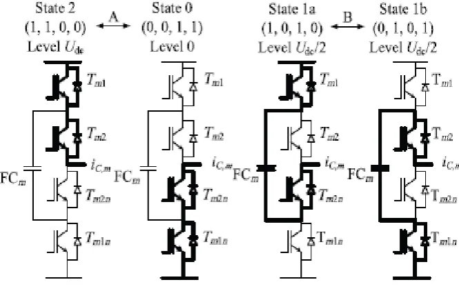
The Design of Shunt Active Power filter includes the number of IGBTs, fig 2 shows available switching states
for single leg of FCC(Flying Capacitor Converter), Let us consider two of possible types of transitions between
states : A) State 2 (1100) ↔ State 0 (0011) B) State 1a (1010) ↔ State 1b (0101)
It is clearly seen that transitions types A and B will cause a simultaneous switching of all transistors in
considered leg leading to high voltage shock on the power component and increase switching losses. Therefore,
these undesirable conditions should be avoided to improve the robustness of the converter. This task can be
handled by the control algorithm.Elimination of the transitions A and B is a step in FS-MP optimization, which
provides a further reduction in the computational demand at every sampling period
Fig. 3Available switching states for single leg of FCC.
The developed approach is based on the comparison of the switching state selected in the previous sampling
time and the state considered in the actual run of the prediction loop. If the undesirable transition is detected in
any of converter
Leg, one of the two actions is chosen:
1) Action 1: the state is eliminated if transition A would occur; the prediction is skipped.
2) Action 2: if transition B would occur the prediction runs normally with a condition that the state will not
change
Nevertheless, Action 2 can influence the dynamics of FCs voltages control. This can be avoided, by adding the
absolute values of the respective FCs voltages errors to the cost function. Thanks to that the FCs voltages fluctuations are insignificant, while elimination of step changes of converter’s output voltage considerably
reduces switching losses and current ripples.This section will be focused on some specific aspects regarding
FCC control with FS-MPC.The three-level FCC contains one FC for each leg and the required voltage level is
half of the dc voltage. The operation of the SAPF system requires ac mains to supply real power needed to the
load and some losses (switching losses of devices, losses in the reactor, and dielectric losses of dc capacitor) in
the SAPF. The reference source currents are used to decide the switching of the SAPF. The system parameter is
967 | P a g e
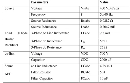
Table 1. System ParametersIV. CONTROL STRATEGY
Instantaneous Reactive Power (IRP) Theory
The method offers the technique to calculate the real and reactive power requirements of the load
instantaneously. The method is mostly applied to calculate the reference current of the SHUC or shunt active
filter.The transformations involved are given in equations (2.1)-(2.8). Three phaseto two-phase transformation is
applied on measured voltages and currents using equations (2.1) and (2.2) where T is the transformation
matrix.A new definition of instantaneous reactive power is presented. This definition has a clear physical
meaning that includes both the conventional instantaneous reactive power and the instantaneous power of a
zero-phase component. A simple control algorithm for the active filter derived from the new definition is
described. Simulations verified the control algorithm. This theory is based on the transformation of three-phase
quantities to two-phase quantities in α–β frame and the calculation of instantaneous active and reactive power in
this frame..The systematic use of active power filters, APF, to compensate non-linear loads, has extended the
use of the instantaneous reactive power theory. Originally, p–q theory appeared; it obtained constant
instantaneous power in the source side after compensation. Later, other formulations have been developed. They
have allowed different compensation objectives to be obtained. Nevertheless, all of them can only be applied to
three-phase systems .This paper presents a new approach which can be applied to multi-phase power systems.
Thus, a new product is introduced that allows an operative definition of the instantaneous reactive power tensor
and the derived instantaneous reactive current component. According to these expressions, different
compensation strategies can be defined in multi-phase systems.
Parameters
Value
Source
Voltage
Vsabc
400 VP-P rms
Frequency
f
50/60 Hz
Source Resistance
Rs abc
0.0287 Ω
Source Inductance
Lsabc
0.2047 mH
Load
(Diode
Bridge
Rectifier)
3-Phase ac Line Inductance
LLabc
2.5 mH
3-Phase dc Inductance
L
dc5mH
3-Phase dc Resistance
R
dc25 Ω
dc-link
Voltage
VDC
700 V
Capacitor
CDC
2000 μF
Shunt
APF
ac Line Inductance
LCabc
4.25 mH
Filter Resistor
RCabc
5 Ω
968 | P a g e
The powers and currents expressions derived from the formulations presented up now can be obtained applying
this new approach. In this work, original p–q and modified p–q formulations expressions are derived in the new
approach framework. In addition, a series of practical examples has been included to improve the understanding
of the proposed formulation The transformations involved are given in equations (2.1)-(2.8). Three phaseto
two-phase transformation is applied on measured voltages and currents using equations (2.1) and (2.2) where T is the
transformation matrix. The instantaneous real and reactive power can be calculated by transformed voltages and
currents using equation (2.3). The calculated instantaneous power has both DC and AC components (2.4 and
2.5). The AC components of the powers originate from harmonics and negative sequence components.
Therefore a high pass filter can be applied to separate the AC components and the compensator reference
current can be calculated using equations (2.6), (2.7) and (2.8). T1 is the reverse transformation matrix
IV. SIMULATION AND RESULTS
Results obtained for the source, injected, load current waveform
Fig 4 Simulation Result For Source Current
969 | P a g e
fig 6 Simulation result for Load CurrentAbove fig shows the MATLAB Simulation results for current waveform, Fig 1 shows the input waveform for
source current Vs time and when any fault occurs in a Distribution System the continuity of supply is not
maintained. Fig 2 shows Injected current, this waveform represent Injection of current by using residual current
at that point where supply is cut off. Fig 3 shows output load current Vs time waveform this shows continuity
supply is maintained.
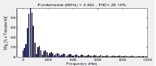
Fig 4 Shows FFT Analysis for total harmonic distortion in which harmonic obtained for input 1shows harmonic
present in source is around 28.15%. Input 2 shows value of total harmonic distortion after injecting current is
13.49. Input 3 shows load side total harmonic distortion which is reduced and value is 0.19%
Harmonics obtained for input 1
Harmonics obtained for input 2
970 | P a g e
Fig.4 FFT Analysis for total harmonic distortionVI.CONCLUSION
In thispaper reference current generation by using IRP (Instantaneous Reactive Power) has been proposed. The
mathematical derivation of the IRP, theory has been employed to Simulated results have verified the
effectiveness of these control algorithms. The simulation results showed that the proposed control algorithm has
good performance in the harmonic compensation and performance under distorted supply voltage condition.
REFERENCES
1. N. Mendalek, K. AI-Haddad, F. Fnaiech and L.A. Dessain,”Nonlinear control technique to enhance dynamic performance of a shunt active power filter” IEE no. 20030488 doi: 10.1049/ip-epa: 20030488 21st
May 2003.
2. Bhim Singh ,JitendraSolanki,” An Implementation of an Adaptive Control Algorithm for a Three-Phase Shunt Active Filter” IEEE transactions on industrial electronics, vol. 56, no. 8, august 2009
3. Roger C. Dugan, Mark F. McGranaghan, H. Wayne Beaty : Electrical Power Systems quality. New York :
McGraw Hill, c1996
4. J. Arrillaga, N.R. Watson, S. Chen: Power System Quality Assessment. New York : John Wiley, c2000
5. Ewald F. Fuchs, Mohammad A. S. Masoum: Power Quality in Power Systems and Electrical Machines.
Elsevier Academic Press, c2008
6. H. Akagi, "New trends in active filters for power conditioning," Industry Applications, IEEE Transactions
on, vol. 32, pp. 1312-1322, 1996.
7. M. El-Habrouk, M. K. Darwish, and P. Mehta, "Active power filters: a review," Electric Power
Applications, IEE Proceedings-, vol. 147, pp. 403-413, 2000
8. Luigi Malesani and Paolo Tomasin, “PWM Current Control Techniques of Voltage Source Converters - A Survey,” IEEE, 0-7803-0891-3/93$03.00, 1993.
9. David M. Brod, Donald W. Novotny, “Current Control of VSI-PWM Inverters,” IEEE Trans. on industry
applications, vol. IA-21. no. 4, may/June 1985.
10. J. Chelladurai, G. SaravanaIlango, C. Nagamani, and S. Senthil Kumar,
11. “Investigation of Various PWM Techniques for Shunt Active Filter,” World Academy of Science,
Engineering and Technology 39 2008.
971 | P a g e
13. Murat Kale, EnginOzdemir, “An adaptive hysteresis band current controller for shunt active power filter”
Electric Power Systems Research 73 (2005) 113–119.