Study of off-axis current drive using EC top-launch in KSTAR
Young-soon Bae1,*
1National Fusion Research Institute, 169-148 Gwahak-ro, Yuseong-gu, Daejeon 34133, Korea
Abstract. The off-axis current drive using electron cyclotron (EC) wave is typically very low due to the low density and temperature and electron trapping effect when it is launched from outside midplane. However, the heating and current drive by EC wave is being regarded as a essential element as an off-axis current drive source together with lower hybrid current drive (LHCD) for advanced tokamak operation research in KSTAR in future. Therefore, the reliable and high efficient ECCD using top launch has been studied for two different launch schemes of down-shift and up-shift resonance with various EC frequencies which will be available in the future KSTAR ECRH system. The ray tracing (GENRAY) simulation studies show that a broad ECCD profile peaked off axis is obtained with a high current drive efficiency for both schemes. It is almost twice as high as that of the outside midplane launch for the fundamental O-mode EC wave.
1 INTRODUCTION
KSTAR aims to develop advanced tokamak operation mode with enhanced broad off axis current drive using off-axis NBI and RF heating devices [1]. In the KSTAR ECRH system upgrade plan, we will install four 105/140 GHz gyrotrons and two 170 GHz gyrotrons with 1 MW output power each. In the pre-liminary study [2], vertical top launch of electron cyclotron (EC) wave shows improvement in EC current drive (ECCD) efficiency with broad ECCD profile peaked off-axis. It is understood that the vertical top launch of EC wave enables nearly vertical trajectories on the low field side from the cold resonance, called “up-shift” resonance. EC waves approaches the resonance slowly with high Doppler shift and waves interact with higher energy electrons during long absorption path, which are less collisional and provide larger ECCD. Also, the long absorption path allows the broad current profile. The other approach of the vertical top launch is the “down-shift” resonance when the EC wave is launched from the higher field side to the cold resonance. It is seen that there is advantage and disadvantage between the down-shift and up-shift vertical launch in terms of launch angle tolerance and current drive efficiency. It will be discussed in the following sections.
Eq. (1) is the Doppler-shifted relativistic EC resonance condition at l’th harmonic.
ω =𝑙Ω
γ + 𝑘||v|| (1) v2
c2 = (1 − 𝜔2
𝑙2Ω2) + 2𝑛|| 𝜔2 𝑙2Ω2
v||
𝑐 − (1 + 𝑛|| 2 𝜔2
𝑙2Ω2) v||2
𝑐2 (2)
Where, is the relativistic factor, is EC wave frequency,
is the cyclotron resonance frequency, k|| (k) is the
parallel (perpendicular) component of the wave number of EC wave to the magnetic field, n = kc/ = c/v is the refractive index, and v is the velocity of electron. Fig. 1 shows ellipses in velocity space using the Doppler-shifted relativistic resonance condition at the fundamental harmonic of 105 GHz with the toroidal magnetic field of 3.0 T at the major radius, R0 = 1.8 m. Note that the
corresponding the cold resonant position is 1.44 m.
Fig. 1. Two different Doppler-shifted relativistic EC resonance
curves using Eq. (2): (left) up-shift resonance and (right) down-shift resonance. The dot line is the trapping boundary. The arrow indicates different radial position of the vertical trajectory from
R = 1.5 m to 1.7 m.
The up-shift resonance condition is obtained with the parallel wave vector k|| > 0 for the co-current drive in the
negative direction (clock-wise, v|| < 0), and the down-shift
resonance condition is obtained with the k|| < 0 and
keeping the same co-current drive (v|| > 0). In the
down-shift case, there are more relativistic resonant electrons with higher energy moving in the counter-current direction than the co-current moving electrons.
we discuss the ray tracing results for the case of the fundamental harmonic up-shift, and for the fundamental and second harmonic down-shift vertical top launches.
2
Ray Tracing Study
The EC wave propagation and power absorption is calculated using the ray tracing code, GENRAY [3] and Fokker-Planck code, CQL3D [4]. In the ray tracing simulation, the toray module in the genray code is used with the finite beam divergence at the launch position and 48 Gaussian zone. The equilibrium is basically double-null shape with elongation, = 2 with the plasma current
Ip = 1.0 MA. The toroidal magnetic field is just scaled for
the different approach of up-shift and down-shift vertical top launch. The plasma density and temperature profile is prescribed with typical H-mode profile obtained in KSTAR experiment as shown in Fig. 2.
Fig. 2. The reference equilibrium and kinetic profiles.
2.1 Up-shift top launch of 105 GHz O1 wave
In previous calculation [2], the vertical top launch of 140 GHz X2 wave with B0 = 2 T at the magnetic axis shows
strong sensitivity of wave trajectory on both azimuthal and polar angles of injection. In this paper, the fundamental O-mode of 105 GHz wave is used for the new vertical top launch study with the toroidal magnetic field of 3 T at the magnetic axis (R0 = 1.8 m). Fig. 3 shows
the wave trajectory and driven current profile obtained from GENRAY simulation for a specific case of injection angles. In this case, the driven current has maximum, ~50 kA/MW at the given density of ne(0) = 7 x 10¹⁹ m-3 and
temperature of Te(0) = 7 keV.
Fig. 3. The ray trajectory and driven current profile for 105 GHz O1 wave obtained from GENRAY code with toray module and 48 Gaussian zone.
The dimensionless current drive efficiency =
ICDR<ne>/Pabs = 50 kA x 1.8 m x 5.65 x 1019 /1 MW =
0.51 x 10¹⁹ Am-2W-1 for this case. In fig. 2, the quantity
plotted for current drive is dIcd = jtordA in each
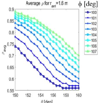
GENRAY’s 200 radial zone. The divergence of the injected wave is defined with half width at half-power, = 1.5 deg. Fig. 4 shows the power absorption and current drive as the polar angle is scanned for each azimuthal angles and for the launcher mirror pivot position of R = 1.6 m and Z = 1.2 m. The launcher mirror pivot position is chosen to have the current profile at the mid-radius. The polar angle () is scanned by step of 0.5 deg for each azimuthal angle () from 100 deg to 107 deg by step of 1 deg. The scanned range shown in fig. 4 is determined to have the power absorption ratio larger than 95%. For 100 deg toroidal injection angle, the power absorption and current drive decreases by 3% and 20%, respectively when the deviation of -5 deg in the polar injection angle from the angle where we have the maximum current drive and full power absorption.
Fig. 4. The power absorption and current drive for injection angles.
When the toroidal injection angle increases, the power absorption larger than 99% is obtained but the current drive decreases because waves are quickly absorbed at the far off-axis as seen in Fig. 5.
Fig. 5. The average radial position of the driven current profile.
Fig. 6 shows the driven current profile and ray trajectory of 105 GHz O1 wave as the plasma density is scanned from 3 x 10¹⁹ m-3 to 10 x 1019 m-3 with fixed central
current drive is obtained with 40-105 kA/MW for ne(0) =
3-10 x 1019 m-3. The corresponding dimensionless current
drive efficiency, = 0.45 – 0.58 x 10¹⁹ Am-2W-1. The
dimensionless current drive efficiency averaged in the range of the density scan is almost same as the one in Fig. 3.
Fig. 6. The EC-driven current profiles and ray trajectories obtained GENRAY and CQL3D code as the plasma density increases. The vertical green dot line indicates the cold resonance line.
Fig. 7. Comparison of second harmonic up-shift vertical top
launch of 140 GHz X2 and O2 waves for ne(0) = 7 x 10¹⁹ m-3
and Te(0) = 7 keV.
Fig. 7 shows the comparison study between two different polarizations of second harmonic up-shift vertical top launch of 140 GHz EC wave. Both cases have similar current drive efficiency of ~ 25 kA/MW. But X2 wave is refracted outward from the cold resonance and its power is not fully absorbed. Note that the launching pivot location is adjusted to get the maximum current drive for each X2 and O2 wave in this simulation.
2.2 Down-shift top launch
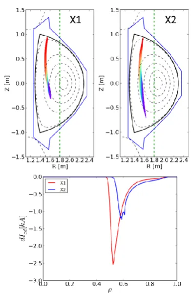
The ray tracing simulation of the vertical top launch at the high field side from the cold resonance location shows the ray trajectory is less sensitive to the wave injection angles. The ray always goes toward the resonance layer for the moderate range of injection angles, then its power is fully absorbed. The less sensitivity of the ray trajectory on the injection angles and full power absorption are considered as the big advantage in the down-shift top launch. Fig. 8 shows the high-field side top-launch for the fundamental harmonic X-mode of 105 GHz (X1) and second harmonic X-mode of 170 GHz (X2) with the same launch position. The toroidal magnetic field at the magnetic axis (R0 = 1.8
m) is 3.75 T and 3.0 T for 105 GHz X1 and 170 GHz X2 wave.
Fig. 8. The ray trajectories of 105 GHz fundamental harmonic X-wave and 170 GHz second harmonic X-wave, and the current drive profile of each case.
drive efficiency is 44 kA/MW and 25 kA/MW. This value is comparable to the up-shift fundamental 105 GHz O-wave and 140 GHz second harmonic X- and O-O-waves. Fig. 9 shows the RF-driven quasi-linear diffusion coefficient in the velocity space with the parallel velocity and perpendicular velocity normalized the thermal velocity for up-shift and down-shift vertical top launch cases investigated in the ray tracing simulation. As expected, the population of the resonant electrons in the velocity space is subject to the harmonic numbers and up-shift or down-up-shift resonances.
Fig. 9. The quasi-linear diffusion coefficient (DQL) in velocity space obtained from CQL3D simulation for (a) the up-shift 105 GHz fundamental harmonic O-wave, (b) the up-shift 140 GHz second harmonic O-wave, (c) the down-shift 105 GHz fundamental harmonic X-wave, and (d) the down-shift 170 GHz second harmonic X-wave.
The current drive efficiency between the vertical top launch and outside midplane launch is compared using the wave of the same frequency and same harmonic resonance, i.e., the 105 GHz O1-wave. But, we used different toroidal magnetic field at the magnetic axis (R0
= 1.8 m) in order to have the same off-axis peak location of the driven current profile: 3.0 T for the vertical top launch and 3.75 T for outside midplane launch.
Fig. 10. The comparison of vertical top launch and outside midplane launch for the same harmonic EC frequency with the
same density and temperature profiles with ne(0) = 7 x 10¹⁹ m-3,
Te(0) = 7 keV.
Fig. 10 shows the comparison of ray tracing and current drive profile of two launches with same density and temperature profiles. The current drive efficiencies are ~ 50 kA/MW and ~ 24 kA/MW for top launch and outside launch, respectively. The current drive efficiency of the top launch is twice as high as that of the outside launch. Not like the X-mode wave, the O-mode wave power is slowly damped and the driven current profile is broad for the outside midplane launch as seen in fig. 10 because the O-mode absorption rate is much smaller than X-mode.
3. Design consideration of top launcher
At present, the divertor upgrade in the KSTAR tokamak is in progress in the design. The divertor upgrade, as well as new concept of the off-axis current drive, is required for the reactor relevant research activity in the next operation phase in the KSTAR.
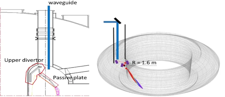
For the new divertor, the single-null configuration is likely to be decided to easily accommodate the top ECRH launcher. The only concern of the vertical top launcher is how to protect the launcher from the ‘vertical displacement event (VDE)’ and plasma disruption. The other issue is the interface with the upper passive stabilizer. Fig. 11 shows the interface of the divertor and the upper passive plate with the conceptual configuration of the top launcher. The waveguide is inserted through the vertical port because the upper slant port is not avaliable any more. Therefore, at least three mirrors are needed to provide the scanning of both toroidal and poloidal injection angles. The all mirrors are protected by the upper passive plate and an ad-hoc protection plate with wave penetration hole.
4. Summary and discussion
This paper presents the further ray tracing simulation study on the vertical top launch in KSTAR following the previous ray tracing simulations focused on the second harmonic X-wave. This study is focused on the reliable and high efficient ECCD using two different launch schemes of up-shift and down-shift electron cyclotron resonance with various EC frequencies which will be available in the future KSTAR ECRH system. The up-shift electron cyclotron resonance is defined that EC wave is launched at the low field side from the cold electron cyclotron resonance location. The down-shift one is the high-field side launch from the cold resonance location. It shows a possibility of the fundamental O-mode wave for the up-shift scheme using 105 GHz in KSTAR with the toroidal magnetic field of 3 T at the magnetic axis. The dimensionless current drive efficiency for the fundamental harmonic down-shift scheme is 0.5 x 10¹⁹
Am-2W-1, twice as high as the outside midplane launch
case. When we compare the second harmonic X and O mode for the up-shift case, the second harmonic O mode is more reliable in terms of the power absorption ratio because the ray path moves toward the resonance location. For the down-shift scheme, the 105 GHz fundamental O-mode will be also possible if the toroidal magnetic field can be raised to 3.75 T at the magnetic axis in KSTAR. It has an advantage of less sensitivity of ray trajectory on the wave injection angles and then ensuring the full power absorption with similar current drive efficiency as that of the up-shift scheme. The 140 GHz and 170 GHz second harmonic X-wave is also possible choice for the down-shift scheme with the toroidal magnetic field ranged from 2.5 T to 3.0 T which is favourable magnetic field range in the nominal KSTAR high experiments. The CQL3D Fokker-Planck calculation for each top launch case shows that the current drive increases by about 20% with broader profile. It results from the non-Maxwellian effect and hence a bit of longer ray path. Considering the synergy effect for the outside midplane launch, the 105 GHz fundamental O-mode EC wave for the top launch will be favourable because the second harmonic resonance exists at the magnetic axis (B0 = 3 T) for 170 GHz EC wave
launched from the outside midplane. In conclusion, the
top-launch approach of ECCD will be an efficient current drive source for the off-axis current drive experiments for the future KSTAR research aiming to the development of the advanced tokamak operation scenario. But for the DEMO device, the top ECCD launch should be carefully assessed through the further modeling studies in the aspect of the compatibility with DEMO operation scenario with very high temperature plasma.
References
1. Y.S. Bae et al., "NUBEAM simulation for off-axis NBI design in KSTAR," American Physical Society (Nov. 16-20, 2015, Savannah, Georgia).
2. Y.S. Bae et al., “Ray tracing study on top ECCD launch in KSTAR,” EPJ Web of Conferences 157, 03003 (2017)(DOI: 10.1051/epjconf/201715703003). 3. Smirnov A.P. and Harvey R.W. Report
CompX-2000–01 Ver 2, (www.compxco.com/genray.html). 4. R.W. Harvey and M.G. McCoy, The CQL3D Code,
Proc. IAEA TCM on Advances in Sim. and Modeling of Thermonuclear Plasmas, pp. 489-526, Montreal, (1992), available through USDOC/NTIS No.
DE93002962; see also,
http://www.compxco.com/cql3d.html CQL3D Manual.