Enhancing Stability of Multi-Machine IEEE 9
Bus Power System Network Using PSS
Divya Prakash
1, Er. Vinay Kumar Tripathi
2PG Student [PS], Dept. of EE, SHIATS, Allahabad, UP, India1 Assistant Professor, Dept. of EE, SHIATS, Allahabad, UP, India2
ABSTRACT: The purpose of this paper is to study and investigate the stability analysis of multi-machine nine bus bar power system network using power system stabilizer. Power system is subjected to sudden changes in load levels. Stability is an important concept which determines the stable operation of power system. The classical three-machine nine-bus system is the simplest model used in studies of power system dynamics and requires of minimum amounts of data. Hence such studies can be connected in a relatively short time under minimum cost. In general rotor angle stability is taken as index, but the concept of transient stability, which is the function of operating condition and disturbances deals with the ability of the system to remain intact after being subjected to abnormal deviations. A system is said to be synchronously stable (i.e., retain synchronism) for a given fault if the system variables settle down to some steady-state values with time, after the fault is removed.
In this paper, we have created a three phase fault at time 0.25 seconds at bus 5 and cleared at time 3.7 seconds. On implementing PSS, the machine achieved a better response in terms of power swing when compared with initial condition. A MATLAB simulation has been carried out to demonstrate the performance of the multi-machine nine-bus system.
KEYWORDS:Power system stabilizer, multi machine, stability analysis, rotor angle stability, transient stability, three phase fault.
I.INTRODUCTION
Power systems generally consist of three stages: generation, transmission, and distribution. In the first stage, generation, the electric power is generated mostly by using synchronous generators. Then the voltage level is raised by transformers before the power is transmitted in order to reduce the line currents which consequently reduce the power transmission losses. After the transmission, the voltage is stepped down using transformers in order to be distributed accordingly. Power systems are designed to provide continuous power supply that maintains voltage stability. However, due to undesired events, such as lightning, accidents or any other unpredictable events, short circuits between the phase wires of the transmission lines or between a phase wire and the ground which may occur is called a fault. Due to occurring of a fault, one or more generators may be severely disturbed causing an imbalance between generation and demand. If the fault persists and is not cleared in a pre-specified time frame, it may cause severe damages to the equipment’s which in turn may lead to a power loss and power outage. Therefore, protective equipment’s are installed to detect faults and clear/isolate faulted parts of the power system as quickly as possible before the fault energy is propagated to the rest of the system.
Simulink is an interactive environment for modelling and simulating a wide variety of dynamic systems. A system is built easily using blocks and results can be displayed quickly. Simulink is used for studying the effects of non-linearity of the system and thus is an ideal research tool. Use of Simulink is growing rapidly for research work in the area of power system and also in the other areas. Time domain simulation method is implemented in this paper. In this paper multi machine nine bus system is modelled in Matlab/simulink and transient stability analysis is done with the fault located in a bus
II. POWER SYSTEM STABILITY
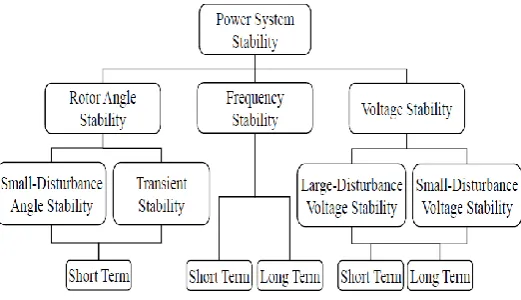
and behaviors. For properly understood of stability, the classification is essential for significant power system stability analysis. Stability classified based on the nature of resulting system instability (voltage instability, frequency instability…), the size of the disturbance (small disturbance, large disturbance) and timeframe of stability (short term, long term). In the other hand, stability broadly classified as steady state stability and dynamic stability. Steady state stability is the ability of the system to transit from one operating point to another under the condition of small load changes. Power system dynamic stability appears in the literature as a class of rotor angle stability to describe whether the system can maintain the stable operation after various disturbances or not. Figure 2.2 shows the classification of power system stability.
Figure 2.1 Classification of stability based on IEEE
2.1 Rotor Angle Stability
Rotor angle stability is concerned with the ability of interconnected synchronous machines of a power system to remain in synchronism under normal operating conditions and after being subjected to a disturbance. The stability of synchronous machines depends on the ability of restoring the equilibrium between their electromagnetic outputs torques and the mechanical input torques and keeping at synchronize with other machines following a major disturbance such as short circuit. Under steady state conditions, there is equilibrium between the input mechanical torque and the output electromagnetic torque of each generator, and the speed remains constant. If the system is perturbed, this equilibrium is upset and instability may occur in the form of increasing or decreasing angular swings of some generators leading to their loss of synchronism with other generators. The change in electrical torque ΔT of a synchronous machine following a perturbation can be resolved into two components as follows:
Te = TS Δδ + TD Δω [1]
Where TS Δδ is the component of torque change in phase with the rotor angle perturbation Δδ and it is referred to as synchronizing torque component. Ts is the synchronizing torque coefficient. TD Δω is the component of torque change
in phase with the speed deviation Δω and it is referred to damping torque component. TD is the damping torque
coefficient.
2.2 Voltage Stability
Voltage stability refers to the ability of a power system to maintain steady voltages at all buses in the system after being subjected to a disturbance from a given initial operating condition. The voltage deviations need to maintain within predetermined ranges. A voltage stability problem occurs in heavily stressed systems, which associated with long transmission lines. Voltage stability depends on the active and reactive power balance between load and generation in the entire power system and the ability to maintain/restore this balance during normal and abnormal operation. The main contributor in voltage instability is the increase of reactive power requirements beyond the sustainable capacity of the available reactive power resources when some of the generators hit their field or armature current time-overload capability limits. The other contributor is the extreme voltage drop that occurs when active and reactive power flow through inductive reactance of the transmission network; this limits the capability of the transmission network for power transfer and voltage support. A typical scenario of voltage instability is unbalance reactive power in the system resulting in extended reactive power transmission over long distances.
As long as the load increases, the power transmitted to supply load also increases while bus voltages on transmission line will drop in inductive network. Close to the maximum transmission capability, a small increase of the load implies a great decrease in the voltage level of the network that may lead to cascaded outages (under-voltages protective devices) while instability occurs in the form of a progressive fall of some bus voltages (voltages collapse).
Generally, the voltage collapse mainly affected by the large distances between generation and load, under load tap changing transformers performance during low voltage conditions, unfavourable load characteristics, and poor coordination between various control and protective systems. In addition, the system may experience uncontrolled over-voltage instability problem at some buses due to the capacitive behaviour of the network and under excitation limiters that preventing generators and synchronous compensators from absorbing excess reactive power in the system. This can arise if the capacitive load of a synchronous machine is too large. Examples of excessive capacitive loads that can initiate self-excitation are open-ended high voltage lines, shunt capacitors,and filter banks from HVDC stations. The phenomena of voltage stability can be classified into small disturbance and large disturbance voltage stability. Small-disturbance voltage stability refers to the system’s ability to maintain steady voltages when subjected to small perturbations such as incremental changes in system load. A criterion for small disturbance voltage stability in that, at a given operating condition for every bus at the system, the bus voltage magnitude increases as the reactive power injection at the same bus increased. A system is voltage-unstable if, for at least one bus in the system, the bus voltage magnitude decreases as the reactive power injection at the same bus increased. Large-disturbance voltage stability refers to the power system ability to maintain steady voltages following large system disturbance such as loss of generation, loss of critical lines, system faults, or protection system failures. Investigation of this form of stability requires the examination of the dynamic performance of the system over a time sufficient to capture the interactions of such devices as under load tap changing transformers and generator field current limiters. The voltage stability can be classified in terms of time into short-term
Stability and long-term voltage stability. Short-term voltage stability involves the dynamics of fast acting load component such as induction motors and electronically connected devices with study period of interest in the order of several seconds. Long-term voltage stability involves the slower acting equipment such as tap-changing transformers and generator current limiters with study period extend several minutes. There are many methods can be used to mitigate voltage instability problem including operation of uneconomic generators to change power flows or provide voltage support during emergencies, using reactive power control and compensation devices, under voltage load shedding to avoid voltage collapse or control of network voltage and generator reactive output.
2.3 Frequency Stability
few seconds. The controllers of all activated generators alter the power delivered by the generators until a balance between power output and consumption is re-established. Spinning reserve to be utilized by the primary control should be uniformly distributed around the system. Then the reserve will come from a variety of locations and the risk of overloading some transmission corridors will be minimized. The frequency stabilization obtained and maintained at a quasi-steady state value, but differs from the frequency set point. The Secondary control, in the portion of the system contains power unbalance, will take over the remaining frequency and power deviation after 15 to 30 seconds to return to the initial frequency and restore the power balance in each control area.
Tertiary control is additional to, and slower than, primary and secondary frequency control, which is supervisory with respect to the secondary control that corrects the loading of individual units within an area. Load shedding used as last option to minimize the risk of further uncontrollable system separation, loss of generation, or system shutdown. Automatic load shedding initiated using under-frequency relays expected to be able to shed the required amount of load during low frequency events. These relays detect the onset of decay in thesystem frequency and shed appropriate amount of system load until the generations and loads are in balance.
III. MODELLING OF POWER SYSTEM STABILISER
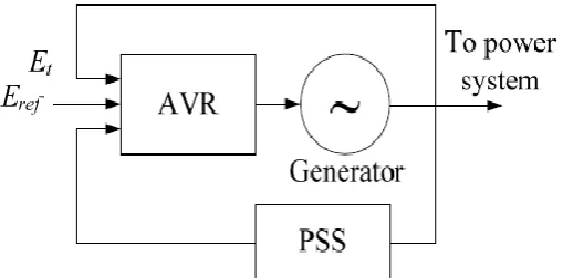
The main function of a PSS is to add damping to the generator rotor oscillations by controlling its excitation. This is achieved by modulating the generator excitation so as to develop a component of electrical torque in phase with rotor speed deviations. The PSS adds appropriate phase compensation to account for phase lag between the exciter input and the electrical torque. This is performed by adding a supplementary PSS signal to the AVR summation input along with terminal and reference voltages. The PSS block diagram is shown in Figure 3-3. Shaft speed, real power, and terminal frequency are among the commonly used input signals to the PSS.
Figure 3-1: Functional block diagram of synchronous generator excitation control system
Figure 3-2: AVR block diagram
exciter input and the generator rotor speed. The PSS gain, K
PSS, is used for amplification and its value is set formaximum amount of damping. The blocks of signal washout, a high-pass filter, and low-pass filter are used to allow signals associated with rotor oscillations to pass unchanged. In addition, the washout block is used to prevent steady changes in speed from modifying the generator terminal voltage. The output of the stabiliser must be limited to prevent damping signals from saturating the excitation system and thereby defeating the voltage regulation function. The positive output limit of the stabiliser is set at a relatively large value in the range of 0.1 to 0.2 pu. This allows a high level of contribution from the PSS during large swings. The negative output limit of the stabiliser, usually in the range of -0.05 to -0.1 pu, is to allow sufficient control range while providing satisfactory transient response and also to prevent unit trip in case of PSS output being held at the negative limit because of a failure of the stabiliser.
Figure 3-3: Power system stabiliser block diagram.
IV. SIMULATION & RESULT
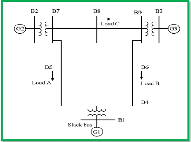
The Matlab software is used to analysis of transient stability of the multi-machine, IEEE nine-bus bar power system network using ieee std 421.5 power system stabilizer. The base MVA and system frequency are considered to be 100 MVA and 60 Hz, respectively. The single-line diagram of the three-machine power system is shown in Fig. 5.1. Here, generator G1 is connected to slack bus 1, whereas generators 2 (G2) and 3 (G3) are connected to bus bars 2 and 3, respectively. Loads A, B and C are connected in bus bars 5, 6 and 8 respectively. The transient stability analysis has been carried out by monitoring the performance of the generators (G1, G2 and G2) and different buses. Two cases have been considered in the transient stability analysis of this power system network. The first case is without three phase fault in power network system and second case is the performance of power system network when three phase fault occurs.
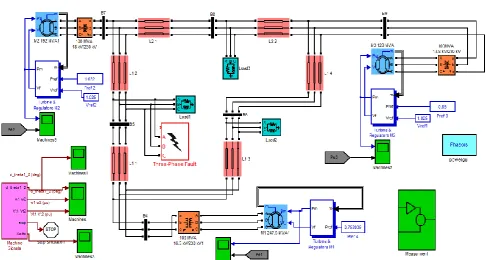
Fig. 5.2: Complete Simulink model of three machine nine bus bar power system network.
Table II- Load Rating
Phase A Phase B Phase C
Load 1 147.3 A 90.06 A 0.002749 A
Load 2 87.45 A 56.32 A 28.53 A
Load 3 103.9 A 61.57 A 44.79 A
Fig. 5.4: Waveform of power system without 3 Fault (i) Voltage of B1,B2 and B3 (ii) Line Power (iii) Power at B4
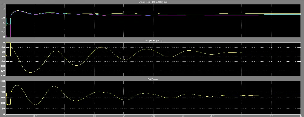
Fig. 5.5: Waveform of with three phase fault – (i) Rotor angle deviation between M1 & M2 (ii) Speed of rotor machine M1, M2 and M3 (iii) Stator Voltage of M1, M2
The 3- phase fault is created at bus 5 at time 0.25 sec and is cleared after time 3.7 sec. the electromechanical oscillations of electrical power is reduced and field voltage is also kept limited, due to this reason excitation is maintained. The various plots of electrical power, field current, and terminal current individually initial, without PSS and with PSS respectively of generator 3 are as shown in figures.
VI.CONCLUSION
This paper presents the improved behaviour of transient stability of a 9-bus multi machine system when implemented with power system stabilizer using Matlab software. The comparison of transient stability performances of the multi machine system. Initially, results of without three phase fault and fault in power system network with power system stabilizer is compared and found that the transient stability of the system is regained after 3.7 sec by system during the three phase fault condition.
REFERENCES
[1] G. Pillai, P. C. Thomas, K. Sreerenjini, S, Baby, T. Joseph, S. Srecdharan “Transient Stability Analysis of Wind Integrated Power Systems with Storage using Central Area Controller”, IEEE International Conference on Microelectronics, Communications and Renewable Energy, 2013, pp. 1-5.
[2] M. Mohamad, N. Hashim, N. Hamzah, N. F. N. Ismail, M. F. A. Latip, “Transient Stability Analysis on Sarawak’s Grid using Power System Simulator for Engineers”, IEEE Symposium on Industrial Electronics and Applications, 2011, pp. 521-526, 25-28.
[3] Carlo Cecati and Hamed Latafat, “Time Domain Approach Compared with Direct Method of Lyapunov for Transient Stability Analysis of Controlled Power System”, IEEE International Symposium on Power Electronics, Electrical Drives, Automation and Motion, 2012, pp. 695-699.
[4] Electric Systems, Dynamics, and Stability with Artificial Intelligence . By James A. Momoh, Mohamed E. El- Hawary,copyright©2000 by Marcel Dekker Inc.
[5] H. H. Al-Marhoon, I. Leevongwat, P. Rastgoufard, “A Practical Method for Power System Transient Stability and Security Analysis” IEEE PES Transmission and Distribution Conference and Exposition, 2012, pp. 1-6.
[6] Hsu, Yuan-Yih et al. "Identification of optimum location for stabiliser applications using participation factors" IEE Proceedings on Generation, Transmission and Distribution, 1987, Vol. 134, pp. 238- 244.
[7] Kavitha R, “Transient stability of IEEE-30 bus system using E-TAP software,”IJSER, vol.3,issue 12,December 2012.
[8] Kundur, P. et al. "Definition and Classification of Power System Stability" IEEE Transactions On Power Systems, 2004, Vol. 19, pp. 1387-1401.
[9] K.R. Padiyar, “FACTS Controllers in Power Transmission and Distribution”, New Age International (P) Limited, Publishers, 2002.
[10] L.Wang ,F Howell ,P.Kundur, C.Y.Ching and w.Xu, “a tool for small Signal assessment of Power Systems,” PICA 2110, Sydney, Australia, May 21-24,2001
[11] M. A. Salam, “Fundamentals of Power Systems”, Alpha Science International Ltd, Oxford, 2009, pp. 336-358.
[12] M. A. Salam and S. Shahnawaz Ahmed, “A New Method for Screening the Contingencies before Dynamic Security Assessment of a Multimachine Power System”, European Transactions on Electrical Power, Vol.14, No.4, 2006, pp.393-408.
[13] M.Klein ,G.J.Rogers,P Kundur,”A fundamental Study of Inter –Area Oscillation in Power Systems,”IEEE Transsactions on Power System.vol 6, No 3,August 1991.
[14] M.J.Gibbard,N. Martin, J.J Sanchez-Gasca, N.Uchida,V Vittal and L.Wang, “Recent Applications of Linear Analysis Techniques,” IEEE Trans. On Power Systems, Vol 16,No 1 February 2002.
BIOGRAPHY
Divya prakash belongs to district pratapgarh of uttar pradesh. He completed three years diploma in IT from CSJM government polytechnic, ambedkar nagar affiliated to BTEUP in 2009. He received his B.Tech degree from moradabad institute of technology, moradabad affiliated to UPTU, lucknow (india) in 2012. He is pursuing his M.Tech in electrical eng. (power system) from SHIATS, Allahabad, UP-India. His field of interest includes power quality, embedded system, programmable logic controller and electric drives.