ISSN(Online): 2320-9801
ISSN (Print) : 2320-9798
I
nternational
J
ournal of
I
nnovative
R
esearch in
C
omputer
and
C
ommunication
E
ngineering
(An ISO 3297: 2007 Certified Organization)
Vol. 4, Issue 3, March 2016
Compact CPW-Fed Uniplanar Antenna for
Multiband Wireless Applications
V.Sandhya Rani1, P.Lokesh Kumar2, S.Varunkumar3, B.Srinivas4, K. Prasanna Kumar5
Department of Electronics and Communication Engineering, LIET, Jonnada, JNTUK, India1,2,3,4,5
ABSTRACT: Patch Antennas are widely used in microwave frequency region because of their computability with
Printed Circuit Board (PCB) technology and its simplicity in manufacture. A compact coplanar waveguide (CPW) fed uniplanar antenna for quad band applications is performed. This uniplanar antenna resonates in four bands so that this antenna is named as quad band antenna.The quad band operation is realized by imposing various current paths in a modified T-shaped radiating element. The antenna covers GSM 900, DCS 1800, IEEE 802.1.a, IEEE 802.1.B.b and Hiper LAN-2 bands and exhibits good radiation characteristics. This low profile antenna has a dimensions of 32mm*31mm when printed on a substrate of dielectric constant 4.4 and height 1.6mm. Simulated return loss and pattern results obtained through software package of HFSS provided and results are obtained.
KEYWORDS:Bluetooth antenna, Compact antenna, CPW-fed antenna, Uniplanar antenna, Quad band antenna
I. INTRODUCTION
The emergence of Coplanar Waveguide (CPW) fed antennas revolutionized the antenna industry in terms of cost, compactness, bandwidth etc. The uniplanar characteristics of CPW structures together with their attractive features like low radiation loss and less dispersion in comparison with a micro-strip, little dependence of characteristic impedance on substrate parameters etc made them Popular. A conventional Coplanar Waveguide (CPW) on a dielectric substrate consists of a center strip conductor with semi-infinite ground planes on either side separated by a small gap. CPW structures supporting quasi TEM mode have gained great attention in microwave and millimeter wave applications due to uniplanar structure. They are commonly used in Monolithic Microwave Integrated Circuits (MMIC).
The CPW transmission lines have lower radiation loss and less dispersion than micro-strip lines. Moreover, the characteristic impedance and phase velocity of CPW are less dependent on the substrate height and more dependent on the dimensions in the plane of the conducting surface. Due to this exceptional behavior, CPW structures have been explored a lot for compatible modern wireless communication gadgets. The introduction of multisystem applications in present wireless communication gadgets, demands the requirement of frequency bands corresponding to system application such as GSM900 (870–960MHz), IEEE802.11.b (2400–2484MHz) bands. Since no compromise can be made on compactness of these electronic gadgets, the multiple antennas must be replaced by multiband antennas with good radiation characteristics, which are of great scenario.
Literature Survey:
A new dual-frequency design of coplanar waveguide (CPW)-fed monopole antenna is proposed and experimentally studied.
The proposed antenna utilizes the advantages of the CPW line to simplify the structure of the antenna into a single metallic level, thereby making easier the integration with the microwave integrated circuits.
II.ANTENNA GEOMETRY
ISSN(Online): 2320-9801
ISSN (Print) : 2320-9798
I
nternational
J
ournal of
I
nnovative
R
esearch in
C
omputer
and
C
ommunication
E
ngineering
(An ISO 3297: 2007 Certified Organization)
Vol. 4, Issue 3, March 2016
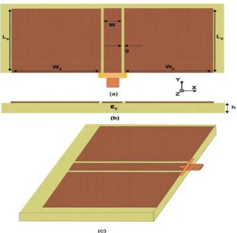
Fig 2.1 a).top view b). side view(c)3D view (Wg=14mm, Lg=10mm, W=3mm, g=0.35mm, h=1.6mm and ϵr=4.4)
III. DESIGN OF THE QUAD BAND ANTENNA
The proposed antenna designed in four steps. This low profile antenna has a dimensions of 32mm*31mm when printed on a substrate of dielectric constant 4.4 and height 1.6mm. Simulated return loss and pattern results obtained through software package of HFSS provided.
DESIGN PARAMETERS AND ITS VALUES
Parameter Value Length of the ground plane(Lg) 10mm
Width of the ground plane(wgL) 14mm
Width of the ground plane(WgR) 14mm
Substarte(L*W*S) 35*34*1.6
Lengths of the strip(L1,L2L+L2R,L3,L4,L5) 18mm,22mm,4mm,8mm,31mm
Substrate permittivity(Er) 4.4
Slit perimeter 3mm Gap in between ground planes 0.35mm
Cd,bc 10mm,29mm
De,ha 1mm
3.1 step 1
ISSN(Online): 2320-9801
ISSN (Print) : 2320-9798
I
nternational
J
ournal of
I
nnovative
R
esearch in
C
omputer
and
C
ommunication
E
ngineering
(An ISO 3297: 2007 Certified Organization)
Vol. 4, Issue 3, March 2016
Figure 3.1 Finite Ground Coplanar Waveguide monopole antenna (Wg=14mm, Lg=10mm, L1=18mm, W=3mm, g=0.35mm, h=1.6mm and ϵr=4.4)
3.2 Step 2
By top loading the monopole we can generate T-shaped monopole (Antenna 2). The dual frequency operation is achieved using a rectangular meander monopole, in this T shaped monopole structure left and right arms of the antenna are equal.it exhibiting dual bands centered at 1.77 GHz and 5.54 GHz. We can generate additional resonance by extending the left arm of the antenna
Figure 3.2 T shaped monopole antenna (Wg=214mm, Lg=10mm, L1=18mm, W=3mm, g=0.35mm, h=1.6mm and
ϵr=4.4) 3.3 Step 3
ISSN(Online): 2320-9801
ISSN (Print) : 2320-9798
I
nternational
J
ournal of
I
nnovative
R
esearch in
C
omputer
and
C
ommunication
E
ngineering
(An ISO 3297: 2007 Certified Organization)
Vol. 4, Issue 3, March 2016
For achieving the triple band characteristics we are using slot monopole antenna, it uses asymmetric grounds. By extending left arm of the T shaped monopole antenna we can generate this Antenna 3. it resonates at 1.61 GHz,2.4 GHz and 5.2 GHz.
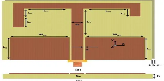
3.4 Step 4
In order to provide better insight to the antenna performance the current distribution on the antenna should be analyzed. A quarter wavelength variations are found along the resonating length for the first two resonances as in the figure. The first resonant path is due to the longer asymmetrical path and the second is due to smaller path. A three quarter variation of current is observed along the shorter asymmetrical path and larger asymmetrical path. Since these two resonances are close to each other they merge together to give a wide bandwidth corresponding to the third resonance.
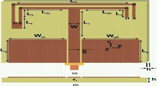
Figure 3.4 Geometry of the Quad band antenna (a) front view (b) side view (L1=18mm, L2R= L2L= 11mm, L3=4mm, L4=8mm, L5=31mm, Lg=10mm,WgR= WgL=14mm, Ws=3mm, CD=10mm, BC=29mm, DE=ha=1mm, h=1.6mm,
ϵr=4.4 and g=0.35mm)
In addition to the three resonances of the antenna the next aim is to generate an additional resonance at 900MHz together with better match for the present bands; preserving the compactness. It is really challenging to excite a lower frequency without trading the compactness of the antenna.
3.5. Modifications in design
For achieving different radiation patterns and for observing the variations in return loss we have to modify the design by placing T shaped slots on either side of the rectangular slots. So that gain and return losses are varied in accordance with the dimensions of T shaped slots.
ISSN(Online): 2320-9801
ISSN (Print) : 2320-9798
I
nternational
J
ournal of
I
nnovative
R
esearch in
C
omputer
and
C
ommunication
E
ngineering
(An ISO 3297: 2007 Certified Organization)
Vol. 4, Issue 3, March 2016
Parametric study for first, second, third, fourth and fifth iterations:
The CPW fed monopole antenna generates two operating modes corresponding to the two monopole lengths. This antenna resonates at 3.6 GHz corresponding to its quarter wavelength.
The dual frequency operation is achieved by using rectangular meander monopole. This proposed antenna is like a T shaped structure with equal left and right arms. It exhibiting dual bands centered at 1.77GHz and 5.54GHz.
The slot monopole antenna uses asymmetric CPW grounds for achieving the triple band characteristics.
Fourth resonance can be generated by introducing a slit. This forces the current to flow through a longer path around the slit.
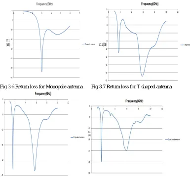
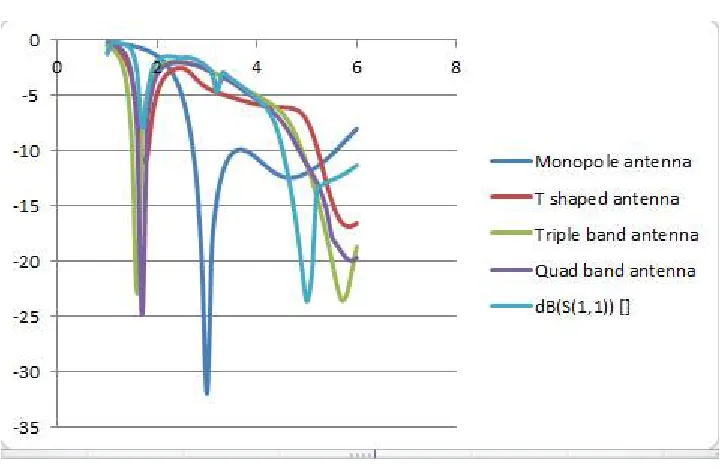
Return loss for different type of iterations are shown in figures below and they are resonates at different types of frequency bands.
Fig 3.6 Return loss for Monopole antenna Fig 3.7 Return loss for T shaped antenna
Fig 3.8 Return loss for the triple band antenna Fig 3.9 Return loss for Quad band antenna
IV.RESULTS AND DISCUSSIONS
ISSN(Online): 2320-9801
ISSN (Print) : 2320-9798
I
nternational
J
ournal of
I
nnovative
R
esearch in
C
omputer
and
C
ommunication
E
ngineering
(An ISO 3297: 2007 Certified Organization)
Vol. 4, Issue 3, March 2016
Fig 4.1 Parametric study for different iterations
Gain for the Quad band antenna is obtained as 2.94db is shown in fig 4.7
Tabular form representing results
Iteration Band width Gain
1 0.9 1.11
2 0.87 1.85
3 1.2 1.25
4 1.4 2.94
ISSN(Online): 2320-9801
ISSN (Print) : 2320-9798
I
nternational
J
ournal of
I
nnovative
R
esearch in
C
omputer
and
C
ommunication
E
ngineering
(An ISO 3297: 2007 Certified Organization)
Vol. 4, Issue 3, March 2016
V. CONCLUSION AND FUTURE SCOPE
This uniplanar antenna resonates in four bands. This proposed antenna having dimensions 0.14 lambda*0.136 lambda*0.007 lambda is presented. It is suitable for several applications like GSM,DCS,IEEE802.11.a, IEEE802.11.b and Hiper LAN-2 bands. The presented proposed antenna having good radiation characteristics with a gain of 3.3 dBi, 2.94 dBi.Future challenges of a micro strip antenna are bandwidth extension techniques, control of radiation patterns, reducing losses / increasing efficiency, improving feed networks.
REFERENCES
[1] R.Sujith,V.Deepu,S,Mridula - CPW fed monopole antenna
[2] Chen H-D,Chen H-T. A CPW-fed dual frequency monopole antenna. IEEE trans antennas propag 2004;52:978-82
[3] Chen H-D. Compact CPW-fed dual-frequency monopole antenna. Electron Lett2002;38:1622–4.
[4] Liu WC, Liu HJ. Compact triple-band slitted monopole antenna with asymmetricalCPW grounds. Electron Lett 2006;42:840–2.
[5] Nashaat DM, Elsadek HA, Ghali H. Single feed compact quad-band PIFAantenna for wireless communication applications. IEEE Trans Antennas Propag2005;53:2631–5.
[6] Guo YX, Chia MYW,Chen ZN. Miniature built-in quad-band antennas for mobilehandsets. IEEE Antennas Wireless Propag Lett 2003;2:30–2.
[7] Ciais P, Staraj R, Kossiavas G, Luxey C. Compact internal multiband antenna formobile phone and WLAN standards. Electron Lett 2004;40:920– 1.