ABSTRACT
ASHCRAFT, JAMES BRITTON. Design and Development of an Expandable Robot Simulation Framework. (Under the direction of Dr. Edward Grant.)
Robotic simulators are useful tools that aid in the design, development, and testing of
a wide variety of robot platforms. A multitude of robotic simulators currently exist, but
many are created to address specific research goals or targeting particular platforms. In
this thesis, a robotic simulation framework is presented that provides the flexibility and
expandability to be useful for multiple types of robot platforms and research efforts. The
simulator is primarily intended to aid with research efforts within the Center for Robotics
and Intelligent Machines at North Carolina State University, but is kept flexible enough
to be used by other researchers as well.
The simulator incorporates 3D dynamics simulation and graphics rendering in hopes
of providing realistic environments and accurate sensor input. Several robot components
are implemented in the current simulator, including a camera sensor, wireless transceiver
module, digital encoder, and touch sensor. DC motors and differential drive modules
provide locomotion for mobile robot platforms. Robot controllers and additional robot
components are implemented through the creation of dynamically loaded modules, which
can be referenced and loaded at run time to provide resources needed for specific
sim-ulations. A text-based configuration system is implemented to allow straightforward
configuration of robot platforms, robot components, and simulation environments.
Experiments have been conducted to demonstrate the usability and flexibility of the
ac-communication with a sensor network using wireless transceivers equipped with
direc-tional antennas. A final set of experiments has been conducted to gauge the performance
of the simulator under various conditions.
The simulator is implemented to run on Microsoft Windows, but care is taken to
select platform-independent libraries for dynamics simulation and rendering to allow the
c
Copyright 2011 by James Britton Ashcraft
Design and Development of an Expandable Robot Simulation Framework
by
James Britton Ashcraft
A thesis submitted to the Graduate Faculty of North Carolina State University
in partial fulfillment of the requirements for the Degree of
Master of Science
Computer Engineering
Raleigh, North Carolina
2011
APPROVED BY:
Dr. H. Troy Nagle Dr. Cranos Williams
DEDICATION
BIOGRAPHY
James Ashcraft was born in High Point, North Carolina to parents David Ashcraft and
Mary Drummond. James attended North Carolina State University as an
undergradu-ate, graduating in 2006 with a B.S. in Computer Engineering and a B.S. in Electrical
Engineering. He enrolled in the NCSU graduate program in fall of 2006 to further his
studies in Computer Engineering. He has been employed through internships at MIT
Lincoln Labs and IBM, and continues to work as a full time programmer for video game
ACKNOWLEDGEMENTS
First and foremost, I would like to thank my wife, Emily, who has always me given
the love and support I have needed to complete my graduate education. Even while I
continued to work full time and started a life with you, you provided me with just the
right amount of encouragement: reminding me politely to concentrate on my studies, but
never doing so in a way that made me feel obligated to finish for anyone but myself.
I would like to thank Dr. Grant for serving as my graduate advisor and advisory
committee chair. Your teaching, advice, and insight through my graduate studies have
not only taught me new concepts, but also forced me to rethink old concepts. Thank
you for being patient with me during periods when I found it difficult to make progress,
but still being willing to proceed full speed ahead when I was ready to do so. Thank
you to Dr. Nagle and Dr. Williams for serving on my advisory committee and providing
interesting discussion on my work.
I would like to acknowledge several colleagues of mine for helping me start and finish
my graduate work. Matthew Craver and Micah Colon, thank you for providing the initial
discussions, ideas, and groundwork that helped spawn the concept of my robot simulator.
Thank you to Nikhil Deshpande, who has graciously worked with me to determine useful
experiments to conduct using my simulator, and for providing real world comparison
TABLE OF CONTENTS
List of Tables . . . viii
List of Figures . . . ix
Chapter 1 Introduction . . . 1
1.1 Motivation . . . 2
1.1.1 Development of New Robot Platforms in the Center for Robotics and Intelligent Machines . . . 2
1.1.2 Desire for Advanced Simulator Capabilities . . . 4
1.2 Other Work in Robotic Simulation . . . 5
1.2.1 Player/Stage/Gazebo . . . 5
1.2.2 Darwin2K . . . 6
1.2.3 Webots . . . 7
1.2.4 M-Rose . . . 7
1.2.5 SimRobot . . . 9
1.2.6 CoRoBa and MoRoS3D . . . 9
1.2.7 UberSim . . . 9
Chapter 2 Simulator Goals and Requirements . . . 10
2.1 Overall Goals and Purpose . . . 10
2.2 Specific Goals and Requirements . . . 11
2.2.1 Operating System . . . 11
2.2.2 Experimentation Speedup . . . 12
2.2.3 Dynamics Simulation and Collision Detection . . . 13
2.2.4 Graphics/Rendering . . . 14
2.2.5 Actuators . . . 15
2.2.6 Sensors . . . 17
2.2.7 Future Robot Components . . . 20
2.2.8 Robot and Environment Modeling . . . 21
2.2.9 Interface Requirements . . . 21
Chapter 3 Simulator Implementation . . . 22
3.1 High Level Simulator Diagram . . . 22
3.1.1 Simulator Core . . . 22
3.1.2 Simulation . . . 25
3.1.3 Configuration Parser . . . 25
3.1.4 Configuration Files . . . 26
3.1.6 Robot Components . . . 26
3.1.7 Robot Instances . . . 26
3.1.8 Static Instances . . . 27
3.1.9 Diagnostics . . . 27
3.2 Software Choices . . . 27
3.2.1 Programming Language - C++ . . . 27
3.2.2 Dynamics Simulation and Collision Library - ODE . . . 28
3.2.3 Graphics Library - OpenGL . . . 29
3.2.4 Windowing System - GLFW . . . 29
3.3 Implementation Details . . . 30
3.3.1 Robot Controllers . . . 30
3.3.2 Robot Component Modeling . . . 31
3.3.3 Configuration System . . . 38
3.3.4 Materials and Surfaces . . . 40
3.3.5 Robot Platform Configuration . . . 42
3.3.6 Environment Modeling - Statics . . . 44
3.3.7 Simulation Configuration . . . 45
3.4 Obstacles and Limitations . . . 45
3.4.1 Lack of Cylinder-Cylinder Collision in ODE . . . 45
3.4.2 Simulation Time Step . . . 46
3.4.3 Controller Interface . . . 48
3.4.4 Actual vs. Simulated Discrepancies . . . 49
Chapter 4 Experiments . . . 51
4.1 Simple Robot Platform Experiments . . . 51
4.1.1 Simulation Configuration . . . 52
4.1.2 Linear Motion . . . 52
4.1.3 Arc Motion . . . 53
4.1.4 Obstacle Detection using Touch Sensors . . . 55
4.2 AMR Sensor Network Experiments . . . 57
4.2.1 Simulation Configuration . . . 59
4.2.2 Mote Sensor Network Experiments . . . 59
4.2.3 Turn Angle Calculation Experiments . . . 64
4.2.4 Sensor Network Navigation Experiments . . . 67
4.3 Performance Metrics . . . 70
4.3.1 Number of Robots in Motion . . . 71
Chapter 5 Conclusion and Future Work . . . 78
5.1 Conclusion . . . 78
5.2 Future Work . . . 80
5.2.1 Integration with Controller Abstractions . . . 80
5.2.2 Improved Configuration Property Editor . . . 82
5.2.3 Graphical Model Editor . . . 83
5.2.4 Improved Modeling of Current Robot Components . . . 84
5.2.5 Support for other Robot Components . . . 85
5.2.6 Advanced Graphical Rendering of Robots . . . 85
References . . . 87
Appendices . . . 89
Appendix A User Guide . . . 90
A.1 Compiling the Simulator Project . . . 90
A.2 Running the Simulator . . . 91
A.3 Keyboard and Mouse Controls . . . 92
A.4 Loading Additional Modules . . . 93
A.5 Adding a New Robot Controller . . . 93
A.5.1 Creating a New Project . . . 95
A.5.2 Implementing the Controller . . . 96
A.6 Adding a New Robot Component . . . 98
A.7 Configuration Property Syntax . . . 102
Appendix B Example Configuration Files . . . 104
B.1 Common Materials . . . 104
B.2 Common Surfaces . . . 105
B.3 Medium Robot Arena . . . 106
B.4 Simple Robot . . . 107
B.5 Linear Movement Simulation . . . 109
B.6 DirectionalAntenna . . . 111
B.7 DirectionalAntenna . . . 113
B.8 Sensor Network AMR . . . 114
LIST OF TABLES
Table 4.1 Linear motion test data. . . 53
Table 4.2 Arc motion test data. . . 55
Table 4.3 Sensor network navigation experiment layouts. . . 68
Table 4.4 Specifications for computer used for performance tests. . . 71
Table 4.5 Moving robots performance test data. . . 74
Table 4.6 Camera sensor performance test data. . . 75
Table 4.7 Memory usage measurements. . . 77
Table A.1 Simulator viewport controls . . . 92
LIST OF FIGURES
Figure 1.1 AMR platform configured for sensor network experiments. . . 3
Figure 1.2 EvBot III robot platform in development. . . 3
Figure 1.3 Webots, by Cyberbotics Ltd. . . 8
Figure 2.1 TMote Sky microcontroller/transceiver by Moteiv. . . 19
Figure 3.1 High level simulator block diagram. . . 23
Figure 3.2 Differential drive robot platform model. . . 33
Figure 3.3 Example camera sensor output. . . 37
Figure 3.4 Example showing use of #import in configuration files. . . 39
Figure 3.5 Texturing the AMR model for the simulator. . . 41
Figure 3.6 Example material and surface configurations. . . 41
Figure 3.7 Example body Configuration using Geoms. . . 44
Figure 4.1 A simple robot platform during simulation. . . 52
Figure 4.2 Simple motion robot paths. . . 54
Figure 4.3 Obstacle detection robot paths. . . 56
Figure 4.4 Sensor network AMR and network motes during simulation. . . . 60
Figure 4.5 Sensor network experiment results, grid layouts. . . 62
Figure 4.6 Sensor network experiment results, random layouts. . . 63
Figure 4.7 Turn angle calculation experiment results. . . 66
Figure 4.8 Sensor network navigation simulation results. . . 69
Figure 4.9 Moving robots performance test graphs. . . 73
Figure 4.10 Camera sensor performance test graphs. . . 76
Figure 5.1 Block diagram using a controller abstraction layer. . . 81
Figure A.1 Using the #loadModule directive. . . 94
Figure A.2 Controller header file template . . . 98
Figure A.3 Controller source file template . . . 99
Figure A.4 Component header file template . . . 101
Figure A.5 Component source file template . . . 102
Chapter 1
Introduction
The aim of this work is to present the design, implementation, and results of new robot
simulation program capable of aiding the research efforts of a wide variety of mobile
robot platforms.
This first chapter discusses the motivation behind the origin of this project and some
other notable work in the area of robot simulation. Chapter 2 discusses the overall goals
and requirements of the simulator, defining the necessary components of the simulation
system and what should be expected from the simulator. Chapter 3 describes the
im-plementation of the simulation system, from the overall software design down to specific
details of smaller components. An introduction to the configuration system and some
limitations of the simulator are also presented here. Chapter 4 details several
experi-ments that are conducted to demonstrate the functionality of the simulator, with some
real world results also presented for comparison. The final Chapter 5 discusses future
1.1
Motivation
1.1.1
Development of New Robot Platforms in the Center for
Robotics and Intelligent Machines
Over the past several years, students in the Center for Robotics and Intelligent Machines
(CRIM) at North Carolina State University (NCSU) have been involved in different areas
of research including evolutionary robotic control algorithms, sensor networks and their
applications to robot navigation, and various biomedical robotics topics. Some of these
projects have involved the design and implementation of new mobile robots, both in
the platform upon which the systems are built, as well as the sensors that are required
for their operation. An example of recent robot platform development in the CRIM is
the autonomous mobile robot (AMR) platform being used for sensor network research
[5], as seen in Figure 1.1. The EvBot III platform seen in development in Figure 1.2 is
another example, which is being developed for studying evolutionary robotics and genetic
controller algorithms.
Although the new platforms can be set up for small physical experiments, it can
be impractical to run experiments requiring a large amount of physical resources. It
is often difficult to deal with a large amount of hardware or is too costly to acquire
the number of robot platforms and components needed for a large scale experiment.
This is particularly true while evaluating the usefulness of an experiment, where a proof
of concept may be necessary prior to large capital investments. To address the need
for performing experiments when physical resource limits are encountered, a variety of
simulation tools have been used in the past. Project-specific simulation environments
tool used for researching evolutionary learning algorithms [17]. However, a tool such as
this is not general enough to be used across multiple projects, so extra time is spent
searching for or developing new tools to aid with other simulations.
The simulator presented in this work is an attempt at creating a simulation framework
that can be used across multiple research efforts and robotic platforms. The software
design will be flexible enough to allow the introduction of new features to support future
robotic research endeavors, without requiring significant changes to core functionality.
1.1.2
Desire for Advanced Simulator Capabilities
Simulation tools can often glance over factors that can be critical to useful simulation of
mobile robots. In the past some aspects of simulation have simply been too
computation-ally expensive or just not feasible to achieve. Computer processors and their supporting
systems are always increasing in computing power and efficiency, not only allowing for
faster simulations, but also bringing new possibilities to light.
To better utilize the capabilities of modern processors, part of the aim of this project
is to allow for useful simulation in the areas of dynamics simulations and graphical
render-ing. While not every robot platform will benefit from graphical simulation capabilities,
machine vision is a common concept in robotics, and will therefore justify the
devel-opment cost of a graphics system in the simulator. More accurate dynamic simulation
and collision detection should provide more realistic interactions between objects than
simple simulation environments lacking proper collision detection. This more realistic
environment should give robotic controller developers additional insight into potential
1.2
Other Work in Robotic Simulation
1.2.1
Player/Stage/Gazebo
Player, Stage, and Gazebo are components of the Player/Stage project [7], a widely used
robot simulation package for use on the Linux operating system. The project is
con-ceptually split into two parts: control architecture (Player) and simulation environment
(Stage/Gazebo).
Player is a robot control abstraction layer that can be used in both real world settings
as well as simulation environments. It is used as an interface between a robot controller
and its sensors and actuators, providing well-defined connections between the controller
and robot components. This not only allows unnecessary details of components to be
hidden from the controller, but also creates a paradigm in which a robot controller can be
transferred from a physical robot platform to a simulated robot platform. As long as the
components of both the physical robot and the simulated robot obey the interfaces defined
by Player, the robot controller should be able to run on a real robot and in a simulator
without requiring any changes. This, of course, requires a simulation environment that
supports the Player interface.
Designed to be compatible with Player, Stage is a simple simulation environment. The
world in Stage operates as a two-dimensional simulation, using top-down plan layouts
of simulation environments which are extruded to form the walls of the environment.
Physics interactions are simulated only in two dimensions, and graphical output is mainly
used for user interfaces. A variety of robot motion styles and popular robot components
Stage.
Gazebo, also part of the Player/Stage project, provides a three-dimensional simulation
environment that is compatible with Player [12, 19]. Gazebo relies on Open Dynamics
Engine (ODE), an open source dynamics simulation engine, for rigid body dynamics
and collision detection. Three-dimensional rendering is used for camera sensors and user
interfaces, providing a more realistic representation of the environment than the Stage
simulator. New robot platforms and their components can be configured through an
Extensible Markup Language (XML) syntax, creating a flexible system of robot modeling.
Gazebo is very similar to the simulator presented in this work in terms of design goals,
configurability, and operation.
1.2.2
Darwin2K
Darwin2K is a robotic simulation package and design tool created to aid robotic designers
when considering different robot configurations for specific tasks [14]. The toolkit uses a
novel parametrized approach to robot configuration that allows evolutionary algorithms
to synthesize mutations of robot configurations over many iterations. The effectiveness of
each iteration is measured through performance constraints and objectives. Darkwin2K
requires a specific simulation to be programmed for each unique task to allow specification
of how the robot operates and meets objectives. The package includes a variety of prebuilt
simulation components such as robot bases, joints, links, and actuators, which can be
1.2.3
Webots
Webots is a mature and well-used commercial robot simulation package for quickly
proto-typing new robot platforms and developing robot controller algorithms[16]. The software
is highly configurable, allowing user control over all object properties such as mass,
fric-tion, and rendering qualities. New robot platforms can be modeled through the user
interface using a variety of robot components and user-specified geometry. Examples
of available components include differential drive bases, distance sensors (infrared
sen-sors, etc.), and camera sensors. Robot platform motion can be handled using a purely
kinematic simulation, or can be configured to use a collision-detection and rigid body
dynamics physics model. Along with highly configurable features, Webots offers a well
laid out user interface that is used for configuring robot platforms and components,
programming robot controllers, and running simulations. Screen shots provided by the
Cyberbotics website [15] show the general layout and look of the simulator package.
1.2.4
M-Rose
M-Rose was developed as a simulation environment for multiple robots learning
coop-erative behavior [2]. The kinematics of specific robot configurations were programmed
into the simulator to allow for fast and efficient simulation of motion. Simulations are
performed in a two-dimensional environment using simple geometric shapes for
model-ing. Results from the simulations were used to allow robot controller to learn cooperative
coordination of actions. These simulation-generated controllers were then used in a real
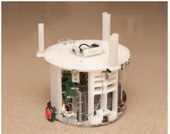
(a) (b)
(c) (d)
Figure 1.3: Webots, by Cyberbotics Ltd. is a commercial robot simulation package.
1.2.5
SimRobot
SimRobot is a robot simulator used for simulation of robots in three-dimensional space,
which has demonstrated its utility in RoboCup applications [13]. The authors of
Sim-Robot have co-developed an XML-based language known as Sim-Robot Simulation Markup
Language (RoSiML) to allow users to specify robot configurations and simulation
param-eters. The user interface of SimRobot includes multiple configurable viewports along with
a scene graph allowing the user to browse and interact with objects in the simulation.
1.2.6
CoRoBa and MoRoS3D
CoRoBa is a multi-robot control and simulation architecture designed alongside the
Mo-RoS3D robot simulator [4]. The CoRoBa control framework is designed to operate around
the CORBA communication middleware, in hopes of providing easy-to-use, platform
in-dependent control of multiple robots whether in the real world or in a simulation. The
MoRoS3D robot simulator is based on Java3D technology, and provides CORBA
inter-faces for all supported robots and sensors to allow communication through CoRoBa.
1.2.7
UberSim
UberSim is a multi-robot simulator developed for simulating games of robot soccer.[1]
UberSim aimed to model accurate interactions between the robots, field, and ball and
utilized the Open Dynamics Engine to help realize this goal. The simulator supports two
specific robot platform types, a three-wheeled omni directional drive robot and a
Chapter 2
Simulator Goals and Requirements
Before implementing a complex software system, it is critical to specify the goals and
re-quirements of that system. The robotic simulation system in this thesis is no exception to
this rule; without the guidance of a set of initial requirements and goals, the development
process could be compromised by time spent pursuing unnecessary ends. It is important
to note that it is possible for the goals and requirements to change slightly over time, but
they are useful nonetheless to give initial direction and motivation to a system. Below,
the high-level goals of the simulator are outlined, and more specific requirements for the
robot simulator are described in the following sections. These specific requirements will
help the simulator achieve the high-level goals.
2.1
Overall Goals and Purpose
Simulation environments, including those not related to robotic research, can offer a wide
variety of benefits and drawbacks when compared to real world environments. High-level
• Ability to quickly prototype possible devices and controls before spending time creating hardware.
• Allow the use of resources in a virtual environment when those resources are not
available in the real world.
• Offer a speed improvement over real world experiments to allow for more
experi-ments to be performed.
• Perform repetitive tasks or tests with easier setup and data gathering than real
world experiments.
• Ability to simulate experiments and further current CRIM research.
These high-level goals set the stage for more specific requirements which are detailed in
the following sections.
2.2
Specific Goals and Requirements
2.2.1
Operating System
The high-level goals do not directly affect a choice of operating system on which the
simulator should run, but this is still a critical item to consider when beginning software
development. Ideally, the simulator would operate on any operating system without
compatibility issues. However, a more realistic approach would be to design the
using Microsoft Visual Studio 9; however, open-source and platform independent libraries
should be used when possible to allow future expansion to other platforms.
2.2.2
Experimentation Speedup
As noted previously in Section 2.1, one of the useful purposes that a simulator can serve
is offering a significant experimentation speedup over physical testing. Computers are
designed to crunch numbers, and many models exist that can describe real world systems
using systems of linear equations or other mathematical representations. Electromagnetic
forces, wireless transmissions, three dimensional rendering, and dynamics simulation are
all examples of physical systems that have well-defined mathematical models that can
programmed into computers. Therefore, it is not unreasonable to expect a simulation
environment to be able to run experiments at an enhanced rate when compared to real
world experiments.
However, this requirement is dependent on many things, including the hardware used
to perform the simulation, the number and complexity of objects in the simulated world,
and the types of sensors and actuators that must be emulated by the simulator. Although
the speed requirement may sound simple at first glance, these details make it difficult to
make specific claims, so no distinct requirement is designed. However, the ability to run
an experiment faster in the simulator than in the real world is desirable.
Aside from an increase in the rate of simulation during an experiment, a simulation
environment should also decrease the time required to set up an experiment. In the
real world, setting up an experiment involves tasks such as constructing physical robots,
downloading controller code to microcontrollers, charging batteries, and placing robots
in their starting positions. The simulation process removes the need for many of these
implies that simulation experiments, robot platforms, and sensor properties need to be
easily configured without requiring major changes to the simulator code base.
2.2.3
Dynamics Simulation and Collision Detection
The need for accurate dynamics simulation is not always apparent for many types of
robot controller simulation. Many robotic systems are designed primarily to operate on
a completely flat two dimensional surface such as the floor of a building. These types of
systems can often be simulated in a simple two dimensional simulation environment that
should offer a speed advantage over a more complex three dimensional world. However,
a simple two dimensional world will not provide the capability to support some types of
robot platforms and will limit the types of environments that can be modeled.
One of the goals in designing this simulator system is for the simulator framework
to be suitable for almost any type of robot system. Although the simulator may not
support every sensor or actuator to enable the simulation of a particular robot platform,
there would ideally be no design limitation preventing the simulation of such a robot
platform if all the sensors and actuators could be adequately modeled. However, if a
two dimensional simulation environment were chosen, that design decision would hinder
the ability to simulate robot platforms that need to operate on uneven terrain, or whose
locomotion styles are not just simple differential drive platforms. A three dimensional
simulation is much more capable and should allow more robotic platforms to be feasibly
simulated. Although this type of simulation is more complex and will cause a performance
2.2.4
Graphics/Rendering
There are two main areas of consideration when determining the necessity of a
graph-ics system for a robot simulator, the user interface and simulated sensor requirements.
Without some type of user interface, any type of software is very difficult to use. There
would be no feedback to the user to indicate whether or not the software is working
correctly; and in the case of a robot simulator, there would be no indication of how a
particular controller is performing. Some software can get by with a simple command
line interface, simple text output that displays messages to inform the user of the current
state of a system. This type of information is of definite use for robotic simulation, as
a robot designer may need to know the specific values of certain controller parameters
throughout a simulation, information that is best represented through alphanumeric text
output. However, robotic platforms are predominant objects that operate in a physical
environment, and one of the main ways that humans can judge performance of a
par-ticular robot platform is watching how the robot behaves in a parpar-ticular environment.
Without this visual feedback to the user, a simulator may be difficult or uninteresting to
use; therefore, this simulator must be designed to support at least rudimentary graphics
for displaying a robot’s behavior in its environment.
Regarding the second area of consideration for graphics, simulation of sensors, it is
important to note that many robot platforms are blind due to the lack of vision hardware.
These platforms, instead, rely solely on other types of sensors for controller input, such
as tactile sensors, encoders, and radio communication devices. So in turn, a robotic
simulator does not necessarily need any type of graphical output to be useful for simulated
controller development. But at the same time, not supporting any type of graphical
sort of vision inputs. Rendering realistic scenes of complex environments using computer
graphics is a non-trivial problem, requiring sophisticated rendering hardware and a lot
of highly detailed modeling of the environment. It is difficult to know how realistic of
an image a controller would require to be useful, but understanding this limitation will
help ease expectations of using vision sensors in the simulator. Sophisticated rendering
systems are beyond the scope of this project, but because some robot platforms may find
a rudimentary graphics systems adequate for simulation purposes, the simulator should
still support some form of graphics.
Pulling these two area of consideration together, it is clear that some type of graphics
systems should be implemented by the simulator. The graphics system will not need to
achieve a high level of realism since it is out of the scope of the project, and a rudimentary
rendering system will be very useful from a user’s perspective and may also prove useful
for some robot systems.
2.2.5
Actuators
For most robotic platforms to be useful, they must be able to move around, or in the
least, interact with their environments. In a real world setting, these movements and
interactions are accomplished through the use of actuators, devices which have some
outward effect on the environment. Perhaps the most common example of actuators on
mobile robotics platforms is that of a simple rotary motor, which creates a torque on the
output shaft when activated through electricity or another method of power. This rotary
be a device which transmits radio waves or other electromagnetic radiation. Although a
person may not witness any direct effect on the environment when such an actuator is
activated, the electromagnetic waves travel outward from the actuator and have a definite
effect on the surrounding environment. These signals may not be detectable by human
senses but can still be useful for communication with other devices.
The examples given above are just two of the many different types of actuators that
could be used effectively on mobile robotics platforms. Realizing that real world robotic
platforms are not generally useful without actuators, it becomes evident that a
simu-lated robotics platform must also be able to use actuators to create noticeable effects
in its simulation environment. Since the goal of this simulation software is to aid the
development of real world robotics platforms, virtual actuators must be created that can
take the place of real actuators. Each virtual actuator must be programmed in a manner
that the pertinent effect created in the simulation environment matches closely enough
with the effect of the real world actuator on the real world environment. If the effects
are largely different, the simulation results may be inaccurate and will compromise the
usefulness of the simulation.
More detailed descriptions of particular actuators which are needed for the initial
simulator are given in the following sections.
Rotary Motor
The rotary motor is a basic building block for the locomotion of a robot within its
environment and for its interaction with the environment. In the very least, this actuator
must be supported to allow a wheeled robotic platform to move itself around a flat
environment. The parameters describing the motor such as output torque and nominal
Motion Base
This actuator is required by some robot platform architectures to create an abstraction
layer between the robot controller and the underlying physical hardware. The motion
base should provide a simple interface for motion commands, and should be equivalent
to those used by a real world system so that porting the interface between the simulation
and real world is feasible.
Wireless Transmitter
This actuator must be capable of communicating with Wireless Receiver sensors in the
simulation environment, sending packets of data and generating a receive signal strength
indicator (RSSI) at the receiver. Varying amounts of output power are allowed on this
transmitter, which will affect the level of signal strength captured by the Receivers.
Transmitters should be capable of being configured with different antenna radiation
pat-terns, allowing for the creation of directional and other non-isotropic antenna models.
This actuator will not need to affect other aspects of the simulation environment (for
example, an extremely high power transmission will not cause interference with other
electronic systems on the robot, as it could possible do on a physical robot). This type
of actuator is integral to the specific robot platform used for sensor network experiments
in this thesis and must be initially supported by the simulator.
2.2.6
Sensors
sensors, it is much more difficult for a robotic platform to operate effectively. For example,
a robotic platform may stubbornly push against an immovable obstacle if it has no way
of detecting that its motion is be impeded. A type of sensor that is commonly applied
to a robotic platform to solve such a situation is a touch sensor, as described in Section
2.2.6. This sensor could give information to the robotic controller regarding the state of
the environment at a specific location relative to the robotic platform. With this type of
sensor, a robot similar to the one above may be able to detect the immovable obstacle,
navigate successfully around it, and proceed with its original task.
There are many different types of sensors currently used as critical components on real
world robotic platforms, meaning that a simulator would be of limited use if there were
no virtual sensors available. In addition to the simple requirement for the existence of
virtual sensors, these sensors must be designed to allow for effective emulation of similar
real world sensors. If the information generated by a virtual sensor deviates too far from
the information generated by the a real world sensor, the robotic platform may operate
incorrectly or gain knowledge and training that does not transfer well to the real world.
Since this simulator is designed to be an aid for developing real world robotic systems,
results that cannot be applied to real robot controllers are not directly useful.
Due to the large number of sensors which are used on current robotic platforms, it
would be out of the scope of this simulator to support all types of sensors that exist. In
fact, that may not even be technologically feasible given some of the limitations of this
simulation system. Therefore, only a subset of actuators need to be implemented in the
simulator, those which will have critical uses on robotics platforms used by the CRIM.
More detailed descriptions of particular sensors which are needed for the initial
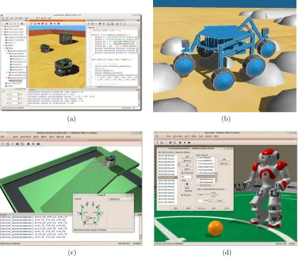
Figure 2.1: TMote Sky microcontroller/transceiver model by Moteiv. This unit has a built-in inverted-F antenna, but can also accept other antenna types through an on-board connector. The microcontroller can be programmed through USB and receives communication via several methods, such as a serial port.
Wireless Receiver
The wireless receiver is a sensor capable of receiving transmissions from a Wireless
Trans-mitter actuator. Similar to the transTrans-mitter, the receiver must also support antenna
pat-terns, which will affect the strength of the incoming signal. The receiver must be able to
receive generic packets of data sent from a transmitter, and must generate a receive signal
strength indicator (RSSI) along with each packet that indicates the power at which the
packet was received. This type of sensor, such as the TMote Sky, seen in Figure 2.1, is
integral to the AMR platform used for sensor network experiments and must be initially
supported by the simulator.
by the simulator. The images produced by the camera sensor need to be representative
of the surrounding environment and objects, but it is well out of the scope of this project
to strive for realism in camera output.
Digital Encoder
Digital encoders, generally attached to rotating components, are devices that create
information regarding the rotation of one part of a robot relative to another part. These
sensors are typically used for estimating the angular distance a robot part has traveled.
This information is useful for determining robot motion (when measuring wheel angles)
and joint angles.
Touch Sensor
The touch sensor is a simple, widely used device that indicates when it has come into
contact with another solid object in the world. Many robots utilize various sensors of
this type, and as such, functionality should be provided to allow for their use in this
simulator.
2.2.7
Future Robot Components
The actuators and sensors described above by no means form a comprehensive list of
components that would allow any robot platform to be modeled. In fact, it is a very small
subset that is required for performing several experiments to demonstrate the operation
of the simulator framework. Other sensors and actuators will need to be added to the
simulator in the future to support new robot platforms and their associated components.
To accommodate this, the robot component framework should be designed in a manner
framework to be rewritten. The modeling of the sensor or actuator and its interaction
with the environment and other components will be the responsibility of the programmer,
but the framework will still need to support the basic addition of these components.
2.2.8
Robot and Environment Modeling
The simulation system should be flexible enough to be able to run different types of
simulations without requiring the code base to be recompiled. This allows for quicker
testing cycles that can be run independently of an development environment or compiler
chain, only requiring the user to have the executable code and any supporting libraries
installed.
2.2.9
Interface Requirements
The goal of this work is mainly to provide a simulation system capable of running
exper-iments. There is no need for a fancy user interface at this point in the project. However,
to keep the user from being completely unaware during a simulation, a basic visual
rep-resentation of the environment and the robots will be required. Also, robot controllers
must be able to write text to an output window during the simulation, so a user can
print out data that is pertinent to the experiment. Alternatively, robot controllers could
Chapter 3
Simulator Implementation
3.1
High Level Simulator Diagram
Before starting to write lines of code for a complex system, it is very useful to begin
with higher level framework design which identifies and groups related functionality. A
system diagram also identifies the links between different system components, allowing for
a visual representation of data flow and communication throughout the system. Without
this, it is more likely to run into unexpected problems later in the implementation phase
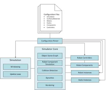
that cause ripple effects in the code base. The high level design of the this simulator can
be seen in Figure 3.1, showing the main components of the simulation system and how
they are connected. The core functionality of each component and sub-components is
described in the following sections.
3.1.1
Simulator Core
The simulator core is what ties all of the critical components together to form a
managing current objects in the simulation, performing robot component simulation, and
managing data between the collision, dynamics, and rendering systems.
Object Scene Graph
This is a small component that contains all objects in the simulation. This component is
used while updating robots and their components in the collision and dynamics systems
and during rendering, when all objects in the scene must be culled for drawing.
Robot Component Simulation
This subsystem contains the necessary code, algorithms, and calculations necessary to
allow for simulation of all the supported component types. Some robot component
sim-ulations are closely related to other subsystems, such as dynamics. Others, such as
transmission of signals between wireless transceivers, operate independently within this
subsystem.
Collision
This subsystem determines what objects in the simulation are colliding, and generates
information that the dynamics system can consume to generate accurate object
interac-tions. Certain aspects of this system are also used for certain types of sensors, such as
proximity or touch sensors, which rely on detecting touching or nearby objects.
Dynamics
The dynamics component allows for simulation of the physics motion of the robots within
the virtual environment. This component takes into account the mass properties of each
realistic and believable movement and object interaction. Without this, robots would not
move, making for a very limited robot simulator.
Rendering
The rendering system provides functionality for generating an image of the scene from a
particular view point when needed by other systems.
3.1.2
Simulation
The simulation component is responsible for the execution of a single simulation instance.
Windowing
The windowing subsystem creates and manages the graphics and O/S resources used to
display information regarding the current simulation.
Update Loop
This component executes a loop, during which the simulator core is updated, and exits
after the simulation is completed. Configuration data is fed in from the configuration
system.
3.1.3
Configuration Parser
The configuration parser understands the syntax of configuration files and is responsible
3.1.4
Configuration Files
These files hold all the necessary information to run a simulation, written using a specific
syntax that the configuration parser can understand. These files not only define
param-eters and properties of the simulation environment, but also define the robot platforms
and components that are used in the simulation.
3.1.5
Robot Controllers
The robot controller system contains the framework necessary to create high level
algo-rithms and machine intelligence which can be used to control simulated robots. These
controllers can identify and communicate with robot resources for sensor input and
con-trol output. An update function on the robot concon-troller is called periodically by the
simulation core to allow them to perform their tasks in sync with the rest of the
simula-tion.
3.1.6
Robot Components
Robot components are the sensor and actuator resources that are configured for specific
robot platforms. These components are created on the robot instances before the
sim-ulation begins, and the simsim-ulation core handles simsim-ulation of these components. Robot
controllers can push and pull data from these components to gather control information
and send control commands.
3.1.7
Robot Instances
Robot instances are individual robots within a particular simulation. Robot instances are
instances can share an identical robot configuration. Robot instances are conceptually
linked with collision and rigid body simulation objects, robot components, and a robot
controller.
3.1.8
Static Instances
Static instances are the inanimate objects required to create a virtual environment, such
as the floor and walls of an office or robot arena. Static instances are similar to robot
instances in that multiple static instances can share a single configuration, but may be
placed in different locations in the simulation environment. This allows for duplicates of
common objects to be placed throughout the scene if required.
3.1.9
Diagnostics
Diagnostics are small objects that hook into the simulator in order to generate output
information based on the state of the simulator. There should be different types of
diagnostics for generating different types of information. How the information is output
depends on the diagnostic class implementation. For example, a useful diagnostic would
be one that prints out the world-space position of a robot at a certain interval into a text
file for later use.
3.2
Software Choices
concepts, and high performance of compiled code. Object-oriented features of languages
such as C++ are useful in many circumstances, allowing for straightforward object
deriva-tion and virtual funcderiva-tions. Powerful language concepts such as templated structures and
functions are useful for creating generic collection structures such as lists and arrays.
Along with the language features that have been proven for many years, C++ also
compiles into native object code for specific target platforms. While this may be an
obstacle for supporting multiple platforms, it creates the opportunity for code to run
faster and more efficiently. This execution speed and efficiency will help meet the design
goal of increased the speedup gained when performing simulations.
3.2.2
Dynamics Simulation and Collision Library - ODE
Implementing an entire physics simulation system from scratch is a complex problem,
and lies out of the scope of this project. To fulfill this necessary component of the
system, a mature open source software package is needed that has a proven track record.
This package is Open Dynamics Engine (ODE), an open source library, written is C++,
that has the capability to perform three-dimensional collision detection and rigid body
simulation [21]. It has been used in many types of software including computer games,
simulation software, and modeling tools, and thus has a well-proven reputation of stable
and efficient operation. These properties make ODE a natural choice to meet the needs
of this robot simulation system.
Along with offering stable collision detection and rigid body simulation capabilities,
ODE also compiles properly for Microsoft Windows and Linux operating systems. This
3.2.3
Graphics Library - OpenGL
Rendering the scene using three dimensional graphics is one of the goals of this simulator,
so a suitable library is necessary to fulfill this goal. OpenGL, a widely used and freely
available graphics library [18], was a natural choice for the simulator. For basic rendering
of shapes, colors, and textures, OpenGL offers a consistent interface that has been used in
numerous applications and is supported on multiple target platforms, including Windows
and Linux. If desired, OpenGL also offers advanced rendering techniques that can be
used to achieve near realistic results. One downside to OpenGL is its requirement to use
extensions to access advanced rendering features, which are more readily accessed on the
more modern Windows specific graphics library, Direct3D. However, for this project, not
many advanced rendering features will be required, so the small cost in coding required
to initialize and use a few extensions is acceptable in return for the otherwise simple and
platform-independent nature of the OpenGL interface.
3.2.4
Windowing System - GLFW
In order to maintain a simple simulator interface that can be used in a platform
in-dependent manner, a library was needed that could provide a single window into which
OpenGL draw commands could be issued. There are several options that were considered
for this project, all of which could have fulfilled the basic requirement:
• the OpenGL Utility Toolkit (GLUT) [10]
For this robot simulator, GLFW was chosen as the windowing system. GLFW not
only provides the core functionality required to render a simulator scene to a window,
but is also very easy to set up and use. It also allows closing the window from within
the program, a feature which allows running a simulation for a specified duration of
simulated time and terminating the process programmatically once the simulation is
complete. Generic mouse and keyboard events can also be processed through GLFW,
allowing for simple control of the viewport in order to watch a simulation in progress.
GLFW provides all of this functionality in a platform-independent manner, maintaining
the possibility of porting the simulator to platforms other than Windows.
3.3
Implementation Details
3.3.1
Robot Controllers
One of the most important aspects of the robot simulator is the system that handles
how high level robot controllers function. Controllers are often the target of analysis or
simply the end goal of research and development of robot system. Without an easy to
use and flexible system for developing robot controllers, the usefulness of the software
would be severely compromised.
When a controller is loaded, it can identify specific resources (sensors, actuators,
and other components) on the robot that are available for use. After initialization,
robot controllers receive periodic updates during which they can communicate with the
robot’s resources in order to control the robot. The robot controller can also access
additional information available through the simulation system, such as robot position
analysis or plotting. However, when generating the the controls for the robot, it is the
responsibility of the controller programmer to not rely on information that would not
normally be available in the real world.
Robot controllers are dynamically loaded at run-time based on what is needed by the
robots in the current simulation. They are kept separate from the simulation core not
only to prevent unnecessary resources from being loaded into memory, but also allows
for users to create and modify robot controllers without needing to recompile the entire
simulation system. This is beneficial to end users who do not require modification of
any other components of the system, and will allow a smaller distribution to those users
because all of the source code is not required.
3.3.2
Robot Component Modeling
Rotary Motor
The rotary motor actuator is available to allow torque output on hinge axes, generally
useful for wheeled robot and powered joints. In this simulator, the rotary motor operates
by applying a torque to the hinge joint in the dynamics simulator. The amount of torque
T applied to the hinge axis is based on the configuration of the motor and the voltage
applied to the motor, using equation 3.1.
T =Gkt
(V − Gω
kv)
R (3.1)
V is the amount of voltage applied to the motor, kt is the torque constant of the
is passed to the hinge joint in ODE for correct dynamics simulation during the next
simulation step.
Differential Drive Motion Base
The differential drive motion base is an abstracted actuator in the simulation system used
to give a robot controller the ability to control a differential drive mobile robot without
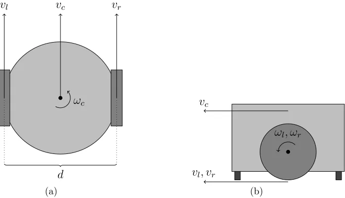
needing to know low level details of the robot platform. A differential drive operates
using a symmetric design with two motors and wheels on opposites sides of a chassis as
seen in Figure 3.2. By driving the wheels at various velocities, the robot platform can
be made to rotate in place and move forward, backward, and along an arc. Knowing the
distance d between the wheels, the radius r of the wheels, and the angular velocities ωl
and ωr of the left and right wheels, the linear and angular velocities of the chassisvc and
ωccan be calculated using equations 3.2 and 3.3.
vc=
rωr+rωl
2 (3.2)
ωc=
rωr−rωl
d (3.3)
These are the details that the robot controller does not want to deal with. Ideally,
the controller could tell the motion base to move in a certain manner, such as to go
straight or rotate in place. Therefore, the interface for the motion base is defined with
the following inputs: linear velocity, angular velocity, linear amount, angular amount.
Setting the desired linear and angular velocities allows the robot controller to command
the platform to rotate in place or move along an arbitrary arc. The linear and angular
vc
vl vr
ωc
d
(a)
vc
vl, vr
ωl, ωr
(b)
Figure 3.2: Differential drive model. A top down view of the system is shown in (a),
and a side view is shown in (b). The chassis linear velocityvcand angular velocityωc are
controlled by manipulating the angular velocitiesωl and ωr of the left and right wheels.
turn.
These four parameters allow the robot to control motion in a natural manner, but
these inputs must be transformed into actual angular velocities that should be applied
to the wheels of the robot platform by manipulating the robot’s rotary motors. Solving
equations 3.2 and 3.3 forωlandωryield the results found in equations 3.4 and 3.5. Based
on the desired linear travel amount xc and angular rotation amount Θc of the chassis,
the necessary total rotation amounts of both the left and right wheels, Θl and Θr, can
be computed as seen in equations 3.6 and 3.7 .
ωl=
vc−ω2cd
Θl =
xc6= 0
xc−xcωcd2vc r
xc= 0
Θcd 2 r , (3.6) Θr =
xc6= 0
xc+xcωcd2vc r
xc= 0
Θcd
2 r
(3.7)
Wireless Transceiver Module
The wireless transmitter and receiver specified earlier are combined into one robot
compo-nent for implementation, as these compocompo-nents are usually simply two different functions
of one component. The wireless transceiver component can send and receive arbitrary
packets of data to other transceivers in the system. The robot controller using this
com-ponent is responsible for creating packets of data for transmission and handling packets
of data that are received by the component. The transceiver will buffer packets until the
controller reads and clears the packets, or until a maximum buffer limit is reached. Along
with the data in a packet, the transceiver module provides a signal strength indicator,
measured in dB, to the controller upon reading.
The transceivers are configured using several parameters, including a maximum
put power, minimum receiver power, and maximum receiver power. The maximum
out-put power is a value in dB that controls with how much power the transmitter can outout-put
a signal, which in turn affects the range at which it can successfully transmit to other
re-ceivers in the simulation. Similarly, the rere-ceivers are limited in what signals they pick up
by the minimum receiver power. Any signal received that is below a receiver’s minimum
receiver power is simply dropped.
simple Friss transmission equation shown in equation 3.8 is used. Developed by Harald
T. Friis at Bell Labs in 1945 [6], the ratio of received power to transmitted can be
computed using transmitter and receiver antenna gains Gt and Gr, signal wavelength
λ, and distance R. The Friis model is ideal, assuming a free space transmission with
no obstacles and no signal reflections, an approximation of real world operation under
different environments.
Pr
Pt
=GtGr
λ
4πR
2
(3.8)
Different antenna radiation patterns may also be specified through the use of
configu-ration files. This allows for the use of directional antennas, which have a radiation pattern
with more receptive lobes in some directions. These different types of antenna can be
used to concentrate transmission power for more powerful transmission or receptions in
some directions, or to attempt to determine the direction of an incoming transmission.
Digital Encoder
The digital encoder is modeled to generate information regarding the rotation of one body
with respect to another. Similar to a real world encoder, the simulated counterparts
can be configured to operate with a specified precision, indicating how many counts
per revolution the encoder should generate. This information can then be read by the
controller at update time to determine the velocities or relative angles of joints.
touches something else in the simulation environment, the sensor is considered to be
active. The controller can check the state of its touch sensors every frame to aid with
tasks such as obstacle avoidance.
Camera
A camera sensor may be attached to any location on a robot body. If a controller requires
an image from the camera sensor, the camera will immediately render the scene from the
perspective of the camera. Configuration settings such as field of view and resolution are
considered when generating the output image. The image is returned to the controller as a
two dimensional array of RGB color data, 8 bits per component, 24 bits per pixel. Figure
3.3 shows an example output from a camera sensor on a simulation using a controller to
move towards a color blob.
Due to the computational expense required to perform this task, the camera sensors
do nothing until they are asked to generate an image. For this reason, a simulation will
run significantly faster if a controller only requests images at periodic intervals instead
of every update frame.
Camera sensors can also be used to save captured images to file during the simulation.
The robot controller can call a function on the camera sensor that will output the current
scene from the perspective of the camera, and store it in a JPEG file specified as a
parameter. These images can be used for later analysis or for use in publications. It
is also possible to store images at regular short intervals, from which a movie can be
generated using external movie editing tools. The JPEG files are encoded with the help
(a) (b)
Figure 3.3: Example outputs of a camera sensor taken during different frames of a
Additional Components
The component system developed for the simulator is designed to allow new components
to be introduced with minimal coding and knowledge of the simulator framework. If
an additional component needs to be added, a new component class can extend an
existing robot component base class that takes care of the basic framework of robot
components. Additional source files would still need to be written that control the
operation, configuration, and simulation of the component systems, and accordingly the
source code must be recompiled for the new component to be integrated. The existing
robot components will serve as good examples of how to implement a new sensor and
should be referenced should that be needed in the future.
3.3.3
Configuration System
There are many different approaches to solving the problem of giving user control over
configuration of robots, environments, and simulations. A graphical editor could be
developed that allows a robot chassis to be modeled specifically for simulation purposes.
A current 3D modeling tool such as 3D Studio Max could be used to export models of
robot platforms, and an importer could be developed that would create the data necessary
for the simulator from the exported model.
However, for this project, a simple and straightforward configuration method is used:
text files. These text files have a syntax similar to a programming language, using curly
braces to delimit object configurations, and simple assignment operators for giving values
to parameters. To read the configuration files and get the information into the simulation
system, a parser was written specifically for the project. A more common syntax such as
// Example s i m u l a t i o n c o n f i g u r a t i o n f i l e u s i n g a #i m p o r t T i c k = 0 . 0 3 // d e f i n e t i m e s t e p
#i m p o r t S u r f a c e s . t x t #i m p o r t M a t e r i a l s . t x t #i m p o r t R o b o t s /MyRobot . t x t #i m p o r t S t a t i c s / MyRobotArena . t x t
#l o a d M o d u l e C o n t r o l l e r s / M y R o b o t C o n t r o l l e r . d l l
S t a t i c a r e n a {
C o n f i g=MyRobotArena Pos = 0 , 0 , 0
}
Robot r o b o t 0 {
C o n f i g=MyRobot Pos = 2 . 4 ,−4 , 0 . 3 HPR= 0 , 0 , 0
M y R o b o t C o n t r o l l e r c o n t r o l l e r {
R o b o t C o n t r o l l e r V a r =5 }
}
Figure 3.4: Example showing the use of an import directive. The three files imported are loaded and parsed just as they were typed in on that line. This is useful for including common information and configurations used by multiple simulations. The Static and Robot instances declared at the end of the file are shown using configurations “MyRob-otArena” and “MyRobot” that would have been defined in the imported files.
makes setting up configuration files more time consuming and painful in the absence of
an external editor.
The configuration process starts by loading a single text file, which should be passed
in as the first command line parameter to the simulator program. The system will then
search for that file, load it, and being parsing the file. Other files can be imported using
an import directive as shown in Figure 3.4. If the configuration parser fails to recognize
the syntax at any point during the parsing process, the configuration will fail and the
simulation will not run. Error messages will be printed to the command line to inform
3.3.4
Materials and Surfaces
All objects in the simulation world require both a material and a surface property. The
material is used by the rendering system to determine how to draw a particular object.
The information contained in a material currently includes a color with which to draw
an object, or alternatively a texture map (image) to apply to an object. Both of these
properties are exposed through the configuration system, with the texture map being
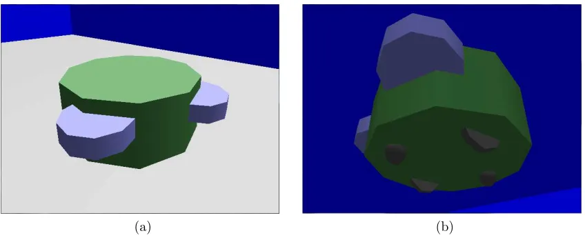
loaded from a JPEG image file if specified, as seen in Figure 3.5 where texture maps are
being used to create a more realistic looking AMR platform in the simulator.
Surface properties contain the information required by the physics system to generate
the correct interactions between objects. The properties exposed for surface properties
are restitution and friction. Restitution controls the amount of rebound that an object
experiences when colliding with another object. For example, a bouncy ball has a very
high restitution, while a bag of sand has almost no restitution. Friction controls the
resistance to motion between two objects when in contact. The typical sliders on the
bottom of a two-wheeled robot chassis have very low friction so that they may slide easily
on floors, but the wheels of a robot usually include a rubber tire around the outside to
achieve higher friction so that the rotating wheel can push the robot.
Materials and surfaces must be declared at the lowest level of configuration, later
referenced by name for application to geoms in robot platform and environment
configu-rations. Declarations inside robot configurations, geoms, or other components will not be
parsed correctly and the simulation will not run. Figure 3.6 shows example configurations
(a) (b) (c)
Figure 3.5: Textures used for the AMR and final model rendered during a simulation. The texture in (a) is mapped around the different sides of the box that represent the chassis of the robot. The wheel texture in (b) is mapped to the cylinders used for the wheels. The final appearance of the robot in simulation is seen in (c), including another texture map used for the directional antenna components.
// e x a m p l e m a t e r i a l t h a t l o a d s an i m a g e f i l e R o b o t C h a s s i s . j p g a s t h e t e x t u r e map M a t e r i a l r o b o t c h a s s i s
{
T e x t u r e=R o b o t C h a s s i s }
// e x a m p l e m a t e r i a l t h a t i s a s o l i d d a r k g r e y , u s i n g s p e c i f i c RGB c o l o r v a l u e s M a t e r i a l d a r k g r e y
{
ColorRGB = 0 . 2 5 , 0 . 2 5 , 0 . 2 5 }
// e x a m p l e p l a s t i c s u r f a c e , w i t h medium f r i c t i o n and r e s t i t u t i o n S u r f a c e p l a s t i c
{
F r i c t i o n =0.2 R e s t i t u t i o n =0.2 }
// e x a m p l e s l i c k s u r f a c e , w i t h z e r o f r i c t i o n , u s e f u l f o r r o b o t s u p p o r t s l i d e r s S u r f a c e s l i c k
{
3.3.5
Robot Platform Configuration
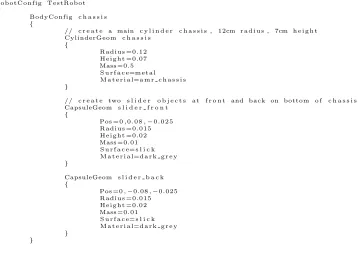
Configuring a robot requires knowledge about the physical form of the robot, what types
of sensors and actuators are on the robot, and specific properties for those components.
The configuration files are built in a hierarchical fashion.
Robot Configurations and Robot Instances
When configuring the robots to be used in a simulation, the user needs to aware of a
distinction between robot configs and robot instances. Robot configs are the templates
that define the shape, properties, and components of a particular robot chassis. Robot
instances are the individual robots that will take part in a simulation, and must reference
a previously defined config in order to populate the environment by building the robot
chassis. Therefore, the configs must be defined in the configuration process prior to
declaring the robot instances.
Robot configurations hold all of the information necessary to build the virtual
rep-resentation of a type of robot. Objects defined by a robot configuration include the
physical geometry shapes that will be used for collision purposes, the masses and surface
properties of all parts of the robot, how different parts of the robot are connected through
joints and axes, and the different robot components that make up the interface between
the robot and the robot controller. More specific details regarding these aspects of robot
platform configuration are given in the following sections.
As previously noted, robot instances reference a particular robot configuration when
they are created. Along with this configuration, world positions and orientations may be
specified to give the robot a starting location in the simulation environment. Each robot