Available online www.jocpr.com
Journal of Chemical and Pharmaceutical Research, 2013, 5(12):690-696
Research Article
CODEN(USA) : JCPRC5
ISSN : 0975-7384
690
The robot intelligent controller design and implementation base on ARM
Jiansheng Peng
1,2, Qiwen He
2*, Qingjin Wei
2,
Zhuocheng Huang
2,
Yiyong Huang
2, Marong
Pan
2, Baoying Lin
2, Degui Yang
2, Siyuan Luo
2and Changfeng Liang
21
National Key Laboratory of Communication, UEST of China Chengdu, China
2
Department of Physics and Mechanical & Electronic Engineering, Hechi University, Yizhou, China
_____________________________________________________________________________________________
ABSTRACT
For realization the controller of robot automatically recognize the peripherals, add or remove, and auto-complete device initialization and peripheral equipment acquisition to intelligent design of the information displayed in human-computer interaction interface proposed to use the Cortex-M3 and Cortex-A8 dual ARM core system architecture. Use the Cortex-M3 core STM32F103VCT6 processor to monitoring of peripheral devices added or removed to complete the sensor data acquisition; use Cortex-A8 core OMAP3530 embedded processor, embedded Linux operating system as relying on QT / Embedded GUI development environment, human-computer interaction interface structures using the method of cross-compile to complete the development of the ARM-side man-machine interface. Through the serial communication STM32F103VCT6 processor OMAP3530 embedded processor data transfer, completion of the collected sensor information to the human-computer interaction interface. Able to complete the automatic identification verified by experiments the robot intelligent controller and initialize peripherals, collected information to the interactive interface.
Key words: OMAP3530, Linux; ARM, Robot Controller
_____________________________________________________________________________________________
INTRODUCTION
Since the world's first remote manipulator was born has been more than 50 years history. With the development of the electronic computer, principle of automatic control theory and the needs of industrial production and the progress and enhancement of related technical , the development of robot technology has gone through three generations: the first generation is programmable robot teaching and reappearing; the second generation is based on the sensor control has a certain discriminant ability of autonomous robot; The third generation is intelligent robot with thinking decision-making ability[1-4]. As the key and core part of robot, the robot controller merits of performance is the key factor affecting the overall performance of the robot[5-8]. It affects the progress and development of the robot in a certain extent. Currently, due to the continuous development and progress of artificial intelligence, computer science and technology, sensor technology, and other related disciplines, making robotics research at higher levels, but also putting forward higher requirements for the performance of the robot controller. Therefore, the design of high-performance robot controller is the current trend in the development of robot technology[9]-10].
THE SYSTEM DESIGN
Qiwen He et al
J. Chem. Pharm. Res., 2013, 5(12):690-696
______________________________________________________________________________
691
Fig.1.
STM32F103VCT6 serial port OMAP3530
the human-computer interaction interface
LCD touch screen SDRAM
Nand Flash Linux system temperature and humidity sensor module color sensor module ultrasonic module motor driver module angle sensor module
Fig.1 Intelligent Robot Controller System Composition Block Diagram
THE MAIN HARDWARE SYSTEM
Robot intelligent controller hardware management module
Robot intelligent controller hardware module management platform, is designed according to the requirement of the system of independent platform, with STM32F103VCT6 processor as the main control chip. Which mainly contains a serial communication interface, three sensors or motor driver module interface, a JTAG interface, the power regulator circuit, etc. Robot intelligent controller hardware module management platform principle diagram is shown in Fig.2.The platform mainly automatically detects whether there is a sensor module or motor driver module is added to the system, if detected module is added to the system, you need to identify what is added to the module in the system (such as a motor driver module and temperature and humidity sensor module), and completes the initialized to a module, reads sensor data or controls the motor drive, etc. Finally, read information parameters through the serial interface to communicate with the OMAP3530 from the module and transfer to human-computer interaction interface for display.
1 2 3 4
A B C D 4 3 2 1 D C B A Title Number Revision Size A4
Date: 23-Dec-2013 Sheet of
File: H:\08级第二课堂毕业生归档文件Drawn By:\陈泳\2008105202 陈泳\电路文件\原理图.ddb VIN 1 O N /O F F 5 G N D 3 OUT 2 Feed Eack 4
R1 LM2596 PA0 23 PA1 24 PA2 25 PA3 26 PA4 29 PA5 30 PA6 31 PA7 32 PA8 67 PA9 68 PA10 69 PA11 70 PA12 71 PA13 72 PA14 76 PA15 77 PB0 35 PB1 36 PB2 37 PB3 89 PB4 90 PB5 91 PB6 92 PB7 93 PB8 95 PB9 96 PB10 47 PB11 48 PB12 51 PB13 52 PB14 53 PB15 54 P C 0 15 P C 1 16 P C 2 17 P C 3 18 P C 4 33 P C 5 34 P C 6 63 P C 7 64 P C 8 65 P C 9 66 P C 10 78 P C 11 79 P C 12 80 P C 13 7 P C 14 8 P C 15 9 P D 0 81 P D 1 82 P D 2 83 P D 3 84 P D 4 85 P D 5 86 P D 6 87 P D 7 88 P D 8 55 P D 9 56 P D 10 57 P D 11 58 P D 12 59 P D 13 60 P D 14 61 P D 15 62 PE0 97 PE1 98 PE2 1 PE3 2 PE4 3 PE5 4 PE6 5 PE7 38 PE8 39 PE9 40 PE10 41 PE11 42 PE12 43 PE13 44 PE14 45 PE15 46 BOOT0 94 VREF- 20 VREF+ 21 OSC_IN 12 OSC_OUT 13 V D D _1 50 V D D _2 75 V D D _3 10 0 V D D _4 28 V D D _5 11 V D D _A 22 V S S _ 1 49 V S S _ 2 74 V S S _ 3 99 V S S _ 4 27 V S S _ 5 10 V S S _ A 19 V B A T 6 N R S T 14 NC 73 R3 STM32F103VCT6_1 C1
104C2104C3104C4104C5104C6104
R E S E T PA0 PA1 PA2 PA3 PA4 PA5 PA6 PA7 PA8 PA9 PA10 PA11 PA12 PA13 PA14 PA15 PB0 PB1 PB2 PB3 PB4 PB5 PB6 PB7 PB8 PB9 PB10 PB11 PB12 PB13 PB14 PB15 P C 0 P C 1 P C 2 P C 3 P C 4 P C 5 P C 6 P C 7 P C 8 P C 9 P C 10 P C 11 P C 12 P C 13 P C 14 P C 15 P D 0 P D 1 P D 2 P D 3 P D 4 P D 5 P D 6 P D 7 P D 8 P D 9 P D 10 P D 11 P D 12 P D 13 P D 14 P D 15 PE0 PE1 PE2 PE3 PE4 PE5 PE6 PE7 PE8 PE9 PE10 PE11 PE12 PE13 PE14 PE15 BOOT0 C14 103 3V3 3V3 Y1 8M C19 22p C20 22p R6 10K + C17 10uF VTref 1 3.3Vsup 2
nTRST 3
GND0 4 TDI 5 GND1 6
TMS 7 GND2 8
TCK 9 GND3 10
RTCK 11 GND4 12
TDO 13
GND5 14 RESET 15 GND6 16
BEGRQ 17 GND7 18
5Vsup 19 GND8 20
C21 ARM_JTAG C23 C10 104 R5 10K 3V3 PB3 PB4 RESET PA13 PA14 PA15 R4 10K 3V3 G N D 1 OUT 2 IN 3
R8 LM117-3.3V D1 LED D2 1N5824 + C13 680uF +C15 220uF+C16
10uF R7 1K R2 SW2-3 L1 33uH 1 2 J1 CON2 5V +C18 10uF 3V3 5V 5V C1+ 1 V+ 2 C1-3 C2+ 4 C2- 5 V-6 T2OUT 7 R2IN 8 R2OUT 9 T2IN 10 T1IN 11 R1OUT 12 R1IN 13 T1OUT 14 GND 15 VCC 16 C22 MAX3232 1 2 3 4 5 6 7 8 9 C24 USART C7 104 C8 104 C12 104 C11 104 C9 104 3V3 PA9
PA10 RXDTXD
1 2 3 J4 CON3 1 2 3 J5 CON3 PA2 PA3 PA9PA10 12 34 56 78 9 10 11 12 13 14 15 16 R9 COMD3 12 34 56 78 9 10 11 12 13 14 15 16 R10 COMD1 1 2 3 4 5 6 7 8 9 10 11 12 13 14 15 16 R11 COMD2 3V3 1 GND 2
DB00 3 DB01 4
DB02 5
DB03 6 DB04 7 DB05 8
DB06 9
DB07 10 DB10 11 DB11 12
DB12 13 DB13 14
DB14 15 DB15 16
DB16 17 DB17 18
CS 19
RS 20 RW 21 RD 22
RESET 23 EN 24
MISO 25 INT 26
MOSI 27 LE 28
SCLK 29
F_CS 30 TP_CS 31 SD_CS 32
R12
COMD32_TFT
5V 5V 5V
PB6 PB7 PB8 PB9 PB10 PB11 PB12 PB13 PB14 PB15 PC6 PC7 PC8 PC9 PC10 PC11 PC12 PC13 PC14 PC15 PD6 PD7 PD8 PD9 PD10 PD11 PD12 PD13 PD14 PD15 3V3 PE0 PE1 PE2 PE3 PE4 PE5 PE6 PE7 PE8 PE9 PE10 PE11 PE12 PE13 PE14 PE15 PC0 PC1 PC2 PC3 RESET 1 2 J2 CON2 1 2 J3 CON2 5V 3V3 RESET
Fig.2 Robot Intelligent Controller Hardware Management Module Schematic
Temperature and humidity sensor module
Qiwen He et al
J. Chem. Pharm. Res., 2013, 5(12):690-696
______________________________________________________________________________
692
applications. The principle diagram of the temperature and humidity sensor module is shown in Fig.3, mainly includes a DHT111 temperature and humidity sensor, a 16 feet double row needle, among which pin 11,12,13 are the hardware module circuit coding part, making the main controller can automatically detect and identify the module.
1
2
3
4
A
B
C
D
4
3
2
1
D
C
B
A
Title
Number
Revision
Size
A4
Date:
23-Dec-2013
Sheet of
File:
H:\08
级第二课堂毕业生归档文件
Drawn By:
\
陈泳
\2008105202
陈泳
\
电路文件
\
原理图
.ddb
1
2
3
4
J1
DHT11
1
2
3
4
5
6
7
8
9 10
11 12
13 14
15 16
J2
COMD16
5-1V
C1
100nF
R1
10K
DATA
R2
10K
Fig.3 Temperature and Humidity Sensor Module Schematic
Ultrasonic sensor module
The module uses HC - SR04 ultrasonic module, high precision, occupies less I/O port resources, using method is simple, the mouth sends a high level of more than ten us, you can wait to output the high level at receiving mouth .Once having output can open timer timing, when the mouth into a low electricity, you can read the value of the timer, it is the distance of time, then you can calculate the distance. Ultrasonic sensor module schematic diagram is shown in Fig.4, mainly includes a 4 pin HC - socket SR04 ultrasonic module, a 16 feet double row needle, among which pin 11,12,13 are the hardware module circuit coding part, making the main controller can automatically detect and identify the module.
A B C D 4
3 2
1
D
C
B
A Title
Number Revision
Size A4 1
2 3 4
J7
Ultrasonic Module
1 2 3 4 5 6 7 8 9 10 11 12 13 14 15 16
J3
COMD16
5-2V C2
100nF R3
10K
Trig Echo
Fig.4 Ultrasonic Sensor Module Schematic
Color sensor module
Qiwen He et al
J. Chem. Pharm. Res., 2013, 5(12):690-696
______________________________________________________________________________
693
1 2 3 4
A B C D 4
3 2
1
D
C
B
A Title
Number Revision Size
A4
Date: 23-Dec-2013 Sheet of
File: H:\08级第二课堂毕业生归档文件Drawn By:\陈泳\2008105202 陈泳\电路文件\原理图.ddb 1 2
3 4 5 6 7 8
R7
Color sensor module
1 2 3 4 5 6 7 8 9 10 11 12 13 14 15 16
J4
COMD16 5-3V C3
100nF R4
10K
5-3V
LED LED
OUT OUT
S0 S1 S2 S3
Fig.5 Color Sensor Module Schematic
Acceleration sensor module
This module uses the ADXL345 accelerometer, ADXL345 is ADI's axis digital acceleration sensor, mainly used in micro inertial devices of consumer electronics, the biggest perceived soil 16g acceleration, sensing accuracy up to 3.9mg / LSB, typically angle measurement error less than 1 degree; through its built-in ADC acceleration signals are converted to digital stored in on chip buffer, using the SPI bus to read the data. Tilt sensor module schematic is shown in Figure6, mainly includes a ADXL345 accelerometer, a 16-foot double needle, among which pin 11,12,13 are the hardware module circuit coding part, achieving this module encodes, making the main controller can automatically detect and identify the module.
1 2 3 4
A B C D 4
3 2
1
D
C
B
A Title
Number Revision Size
A4
Date: 23-Dec-2013 Sheet of
File: H:\08级第二课堂毕业生归档文件Drawn By:\陈泳\2008105202 陈泳\电路文件\原理图.ddb 1 2
3 4 5 6 7 8 9 10 11 12 13 14 15 16
J6
COMD16 5-4V C5
100nF R6
10K
1 2 3 4 5 6 7 8 9 10
R19
Acceleration sensor module SCL
SDA SDO
VS
INT0 INT1
CS
SCL SDA SDO
Fig.6 Acceleration Sensor Module Schematic
Motor driver module
This module uses L298N chip drive motor, L298N is a high voltage, large current of motor driver chip produced by ST company. The chip encapsulation uses 15 pin. The main features: high working voltage, high voltage can be up to 46 v, output current is big, instantaneous peak current can reach 3 A, the maximum current to use continuing work is 2 A , rated power is 25 W. Internal contains two H bridge of high voltage and large current full bridge driver, can be used to directly drive dc motor, stepping motor, load relay coil, etc. Motor drive module schematic is shown in Fig.7, mainly includes a L298N chip, a TLP521-4 optical isolation chip, achieving level matching, a 3.3V voltage regulator circuit, a 16-foot double-pin, among which pin 11,12,13 are the hardware module circuit coding part, achieving this module encodes, making the main controller can automatically detect and identify the module.
1 2 3 4
A B C D 4
3 2
1
D
C
B
A Title
Number Revision
Size A4
Date: 23-Dec-2013 Sheet of
File: H:\08级第二课堂毕业生归档文件Drawn By:\陈泳\2008105202 陈泳\电路文件\原理图.ddb IN1
5 IN2 7
IN3 10
IN4 12
NEA 6
NEB 11
GND
8 IS ENA 1
IS ENB 15 VSS 9
VS 4 OUT1 2 OUT2 3 OUT3 13 OUT4 14
R18
LN298
IN1+ 1
IN1-2
IN2+ 3
IN2-4
IN3+ 5
IN3-6
IN4+ 7
IN4-8 OUT4+OUT4- 9
10 OUT3- 11 OUT3+ 12 OUT2- 13 OUT2+OUT1- 14 15 OUT1+ 16
R13
TLP521-4
G
N
D
1
OUT
2 IN 3
R12 LM117-3.3V
C6
104 D1
1N4007 D2 1N4007
D3 1N4007
D4 1N4007
D5 1N4007D61N4007D71N4007D81N4007
1 2 3 4
J8 CON4
+
C7
100uF R11
200 R10 200 R9 200 R8 200
R14 4.7K R15 4.7K R16 4.7K R17 4.7K
5-5V 3.3V
IN1 IN2 IN3
OUT0 OUT1 OUT2 OUT3 IN4
Motor driving module
5-5VFig.7 Motor Driver Module Schematic
The description of system automatically recognizes the hardware
Qiwen He et al
J. Chem. Pharm. Res., 2013, 5(12):690-696
______________________________________________________________________________
694
modules, so in the system can according to the different code identify the corresponding modules, and complete the initialization for the corresponding modules. Hardware circuit coding schemes is shown in Fig.8, 11,12,13 pin for the module code. Of course, system automatically recognize module needs to know the hardware module is added, so the robot intelligent controller hardware module management platform of hardware module in the interface is connected by software programming to detect hardware module coding of I/O pins on the premise of without inserting hardware module are all the bottom level, once detected all the bottom level is not completely the bottom level, suggesting a new hardware module is added, similarly, when the connection hardware modules coded I/O port is detected, and never the whole of the bottom level turn to the whole of bottom level shows that hardware is removed from the system. System is through continuous testing I/O pins level connected hardware module coding circuit changes, so as to achieve automatic identification hardware modules are added or removed.
1 2 3 4
A B C D 4
3 2
1
D
C
B
A Title
Number Revision
Size A4
Date: 23-Dec-2013 Sheet of
File: H:\08
级第二课堂毕业生归档文件
Drawn By:\陈泳
\2008105202陈泳
\电路文件
\原理图
.ddb 1 23 4 5 6 7 8 9 10 11 12 13 14 15 16
J5
COMD16
5-5V C4
100nF R5
10K
D4
[image:5.595.209.379.541.746.2]IN1 IN2 IN3 IN4
Fig.8 Hardware Module Coding Schematic
THE MAIN SYSTEM SOFTWARE
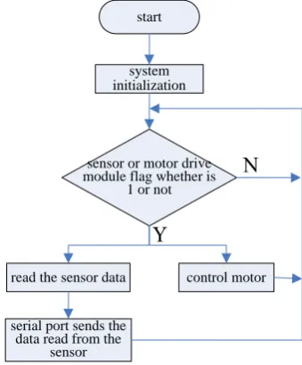
Hardware management platform programming refers to the program designing of the end of STM32F103VCT6 processor. through the programming completed the various sensor modules or motor-driven modules intelligent management, that achieved automatic detection sensor module added or removed, when you add the module to automatically identify the added module is what modules (such as the temperature and humidity sensor module or ultrasonic sensor module), and then automatically initializes the module based on the identification, and mark the corresponding flag module, the main program through the flags to determine the corresponding module will know that the module is added to the system. Clearing the flag when it detected the corresponding module is removed from the system. The main program flow chart is shown in Fig.9, when the hardware management platform startup, system initialization, including the system clock, the serial port initialization, timer initialization, after the completion of system initialization, entering into while loop to determine the corresponding module flag whether 1 or not, when the flag is 1, indicating that the system has been added to the corresponding module, then the corresponding module operating, Including reading sensor data, serial transmit data, control motor and so on, after completed the corresponding module operation entering the next cycle. When the flag is not 1, directly entering into the next cycle.
system initialization
start
sensor or motor drive module flag whether is
1 or not
read the sensor data
serial port sends the data read from the
sensor
control motor
Qiwen He et al
J. Chem. Pharm. Res., 2013, 5(12):690-696
______________________________________________________________________________
695
Automatic detection sensor module or motor driver module is added to the system or removed from the system, which mainly implemented in the timer interrupt service function. Start the timer interrupt service function, when the regular time STM32F103VCT6 processor jumps into the timer interrupt service function for processing. Timer interrupt service function flow chart is shown in Fig.10, firstly, testing whether there is a new hardware module is added to the system in the timer interrupt service function, if there is a corresponding module logo sign bit is 1, and the newly added hardware modules are initialized, after the completion of the initialization, exiting timer interrupt service function, if not then directly exiting the timer interrupt service function; In detecting whether there is a new hardware module is added, at the same time, also detecting whether there is a hardware module little removed from the system, if there is a new hardware module clears the corresponding flag bit is 0, then exiting the timer interrupt service function, if not then directly exiting interrupt service functions.
enter the timer interrupt service
function
detect whether there is a module added to the system
module
initialization
exit the interrupt service function
detect whether there is a module removed from the
system
flag bit set 1
flag bit set 0
Fig.10 Timer Interrupt Service Program Flow Chart
THE MAIN SYSTEM SOFTWARE
In the Linux system of PC using QT to develop human-computer interaction interface, through crossing compiler ported to OMAP3530 development board, has been tested can run properly in the development board, interactive interface test results is shown in Fig.11.
Fig. 11 The Human-computer Interaction Interface Test Rendering
Qiwen He et al
J. Chem. Pharm. Res., 2013, 5(12):690-696
______________________________________________________________________________
696
Fig.12 System Automatically Recognizes the Hardware Test Pattern
CONCLUSION
Robot is the product of multiple interdisciplinary, integrated multi-disciplinary field of advanced theory and technology, includes dynamics and kinematics, mechanical design and manufacturing, computer hardware and software, control and sensors, pattern recognition and artificial intelligence, and the robot's controller is the core part of the robot. This design uses STM32F103VCT6 processor and the double ARM ernel of OMAP3530 processor architecture for building platform, making full use of rich STM32F103VCT6 resources, processing speed is moderate, high cost performance, rich OMAP3530 processor resources, high processing speed, convenient for embedded designing and development. Eventually achieved a robot intelligent controller automatically recognizes the hardware, achieving the effect of plug and play, making robot intelligent controller becomes simple and convenient in practical applications, has important significance for the development of robot intelligent controller.
Acknowledgements
The authors are highly thankful for the Guangxi Natural Science Foundation(ID: 2013GXNSFBA019282), Guangxi university research projects (ID: 2013YB205), Hechi College special projects (2003ZX-N003), Chinese College Students' Innovative Entrepreneurship Training Program(ID: 201310605008, 201310605009, 201310605010) and Guangxi Students Projects of Innovation and Entrepreneurship Training Program (ID: 1100, 1101, 1109, 1110, 1111).
REFERENCES
[1]Biglarbegian M, Ieee: On the Design of Robust Intelligent Controllers with Application to Mobile Robot Tracking. In: 2012 American Control Conference. 2012: 4879-4884.
[2]Hassanzadeh I, Alizadeh G, Hashemzadeh F, Kharrati H: P I Mech Eng I-J Sys2011, 225(I3):385-392. [3]Huang H-C: Ieee Transactions on Industrial Informatics2013, 9(4):1828-1835.
[4]Huang H-C: Ieee International Conference on Systems, Man, and Cybernetics. 2011: 2267-2272.
[5]Javier Marin F, Casillas J, Mucientes M, Transeth AA, Fjerdingen SA, Schjolberg I:: Intelligent Robotics and Applications, Pt Ii. Edited by Jeschke S, Liu HH, Schilberg D, vol. 7102; 2011: 525-535.
[6]Kumar SM, Kumar MD, Dayal PR, Prasad SM: Mems, Nano and Smart Systems, Pts 1-6. Edited by Yuan L, vol. 403-408; 2012: 4777-4785.
[7]Li T-HS, Yeh Y-C, Wu J-D, Hsiao M-Y, Chen C-Y: Ieee T Ind Electron2010, 57(5):1687-1700. [8]Sharbafi MA, Lucas C, Daneshvar R: Ieee T Syst Man Cy C2010, 40(6):630-638.
[9]Tsai C-C, Wu H-L, Lee Y-R: International Journal of Nonlinear Sciences and Numerical Simulation 2010, 11:91-95.