Verification and Implementation of Video
Security and Surveillance System
Mishrak Sharma1, Prerna Paliwal2
M.Tech Student, Dept. of Electronics and Communication Engineering, Ganpat University, Kherva, Mehsana, India1
Technical Associate, Dept. of Embedded System, eiTRA, Umiya campus, Ahmedabad, India2
ABSTRACT: This paper is all about Implementation of a Security and Surveillance system which captureslive video status and stores the events on SD-card and then to main server. It uses different sensors for taking the data like speed sensor, gyroscope sensor, temperature sensor, light sensor etc.This systemis being installed in Vehicles. It is very useful for police investigation to recreate the scenario, which has been occurred during the accident, It is very useful for Insurance companies also, for finding out the root cause of accident crash, because of the cameras mounted surrounding to vehicle these cameras will make driver more alert to follow traffic rules and make no mistakes as his all actions have been captured by those cameras and data are directly send to server, which makes driver more alert and aware. It also shows routes taken by the driver so that if any vehicle go out of its area that also can be view by owner.
KEYWORDS: Security and Surveillance System, Microcontroller, Microprocessor, Windshield Unit (WU), Under dash Unit (UDU), Sensors
I. INTRODUCTION
The system continuously records the video around it and whenever any major fluctuation in the reading of data, known as event occurs it typically cut down 20 seconds before the collision and 10 seconds after collision video through software coding from continuous recording of video. This system is being installed on the windshield and under the seat desk and feature a camera as well as a Global positioning system (GPS) unit and collects the performance data such as accelerating, braking and turning etc. The data is stored to a secure digital (SD) card similar to those that are used in analog cameras and can be reviewed on a computer.
There are so many products available which works same as this but the functionalities and specifications which makes this system different from others are as below.
Its compact size of Hardware.
High quality of picture 720 x 480, working on 30 fps.
Different sensors attached
o Accelerometer sensor – for detection of speed of vehicle. o Gyroscope sensor – for angular measurement of vehicle. o Temperature sensor – for measurement of current temperature. o IR-led & grayscale sensor – for night capturing of video.
This system is even more accurate than those that are currently being installed in vehicles because it also records the time, location and direction of the driving as well as the driver’s view which makes it very helpful for a number of hard-to-prove situations.
Hard-to-prove situation as in when you are driving your vehicle and there is a yellow light on the traffic signal, that means you can pass through the road but you need to be careful but still if any traffic police stops you for breaking the rule of traffic signal. Here you don't have any evidence which proves, you have driven your vehicle when traffic signal is yellow. Hence the situation like Hard-to-prove this system plays a very vital role.
The basic functions of a system should include continuous audio/visual recording from all the camera of the vehicle. GPS and time/date data will also be recorded in order to determine the location of the incident.
A. Hardware:
Hardware design which contain DM8148 processor, MSP430FR6889 and MSP430G2553, micro controller, temperature sensor, light sensor, accelerometer, gyroscope, IR-LEDs, LEDs, backup battery, six external cameras and two internal cameras.
B. Software:
Fig 1 shows different modules of software design. It is purely C and embedded C language coding for interfacing between Hardware, Device driver and Software.
Fig 1. Software Architecture
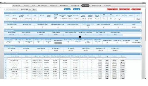
C. Web User Interface:
Web user interface which is made up of combination of different languages. Graphical user interface has been done in HTML5, back-end coding is being done in JavaScript, presentation of pages like colors and formatting is being done in cascading style sheet i.e. CSS and tabular format handling is being done through jqgrid.
Fig 2. Web User Interface
II. RELATED WORK
A. Car Black Box[1]:
Black box is a term or a system mainly used for airplane for event occurrence to identify what was gone wrong in plane before accident but now this system is also used for cars.
a. Benefits of Car Black Box:
Just like “black boxes” help determine the cause of an airplane accident, car black boxes help determine what has caused a car accident and the events that led to collision. They are particularly valuable when no witnesses are present at the scene of the accident and when each driver has his/her own version of the events. The benefits of car black boxes for reconstruction of the events before accident are also emphasized by accident investigators, the police and increasing number of insurance companies which now have a powerful tool to determine whether the claim is justified or not. So why would you want to install a device that can enable the insurance company to reject your claim? Well, the benefits of a car black box outweigh the drawbacks in virtually all aspects. The car black box can get you into jail if you are a reckless driver but it can also save you from it. For example, an accident on an remote area without any witnesses present may be very difficult to reconstruct and it is possible to be put on trial even if you did not cause the accident. With a car black box, that cannot happen. Why? Because the small device that is installed in your vehicle under the seat, behind the dashboard or even better on the windshield records several key actions you have made before the collision including the speed of your engine, accelerating, braking, turning, etc. which typically reveals enough information to charge you for causing an accident or help you prove your innocence. Also, with a car black box that includes a camera there will be no longer your word against the police officer’s, while your insurance claims will be approved a lot faster.
Insurance companies have shown a great interest in widespread use of car black boxes because the data obtained from the device reveal a great deal about the drivers. In fact, some insurance companies have even offered a discount for drivers who have installed a car black box because it enables them to evaluate which drivers that are less likely to get involved into an accident and lower their premiums, while increasing the rates to “risky” drivers. This also means that the device can help you save money for your car insurance if you drive safely. In addition to insurance companies and car accident investigators, car black boxes are also very useful for car rentals because any disputes about car damage can be easily resolved by reviewing the data from the device. These are typically stored on a secure digital (DS) card, while all accidents are stored automatically. However, this is good news for the customers as well because they will no longer be charged for car damage they have not done.
b. Disadvantage of Car Black Box:
Technology and monitoring cost is very high to afford.
At the same time voice recording and audio recording not possible.
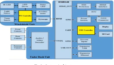
III.SYSTEM ARCHITECTURE
Fig 3. System Architecture
Fig 3. Shows the System Architecture, it includes the following two major modules.
A. Under Dash Unit (UDU):
a. UDU Mother Board:
UDU mother board is the main board of the System. It is designed around the DM8148 Soc. Following are the major blocks in UDU mother board.
TI DM8148 Soc.
2GB DDR3 RAM
512MB NAND Flash
USB and HDMI Interfaces
Analog Audio/Video decoder section (2x TVP5158) to decode
Micro SD card interface
Ethernet Interfaces
14 pin Expansion connector to provide for 4x Discrete I/O, I2C, RS232 interface
HDMI Display UDU mother board and power board interfaces through 40 pin connector
b. UDU Power board:
UDU Power board has been designed to generate and provide the required power supply needed for the functionality of the UDU motherboard and few sections on the UDU power board. The system is designed to operate on the input supply of 9-16 Volt, which is provided by the vehicle Ignition or Battery supply. 12V input supply is provided to the power board and following supplies are generated inside the power board 5V, 3.3V, 1.8V, 1.5V, 1.1V. UDU power board also includes the power monitor section and Audio amplifier section.
B. Wind Shield Unit (WU):
This is the second major unit of the System; this unit is interface with UDU through HDMI cable. WU Module consists of following boards.
a. WU Mother Board:
WU mother board includes following major blocks.
Customized HDMI interface with UDU mother board.
LED driver.
Accelerometer.
Temperature sensor.
Ambient light sensor.
Microphone interface.
Event Switch.
3G Board interface.
Internal camera interface.
Speaker interface.
2x IR LED board interface.
b. WU 3G board:
3G Board is used to access GPS, 3G GSM/CDMA functionality. This board is interfaced to the WU motherboard through a 4-pin connector which includes the USB interface and the 5V power supply generated by the WU motherboard.
IV.HARDWARE RESOURCES
The hardware consist of 3 major parts
A. Processor [2]:
It is a high performance video processor with 1-GHz ARM cortex-A8 RISC Core.
32 KB of instructions and data caches.
512KB of L2 caches.
64KB of RAM, 48KB Boot ROM.
It’s a little endian processor withHigh definition video processing sub- system (HDVPSS).
Six UARTs.
Four i2c master slave interface.
Parallel Camera Interface (CAM).
128 General-purpose input/outputs(GPIOs).
B. Sensors:
a. Speed sensor [3]:
The ADXL375 is a small, thin, 3-axis accelerometer that provides low power consumption and high resolution measurement up to ±200 g. The digital output data is formatted as 16-bit, twos complement data and is accessible through I2C digital interface.
It follows First in First out (FIFO) data scheduling.
It is operating on 2.0 V
b. Gyroscope sensor [4]:
The BMI055 is an inertial measurement unit (IMU) for the detection of movements and rotations in 6 degrees of freedom (6DoF). It reflects the full functionality of a tri axial, low-g acceleration sensor and at the same time it is capable to measure angular rates. Both – acceleration and angular rate – in three perpendicular room dimensions, the x, y and z-axis. It is mainly used in senses tilt, motion, inactivity and shock vibration in cell phones, handhelds, computer peripherals, man- machine interfaces, virtual reality features and game controllers.
It is operating on 2.4 V
c. Temperature sensor [5]:
TCN75A temperature sensor converts the temperature between -40 oC and +125 oC to a digital word, with +-1.5
o
C accuracy. This sensor has 2 wire, I2C compatible serial interface, allowing up to eight devices to be controlled in a single serial bus.
It is operating on 2.7 V
d. Light sensor [6]:
The OPT3001 is a sensor that measures the intensity of visible light. The spectral response of the sensor tightly matches the photonic response of the human eye and includes significant infrared rejection. The OPT3001 is a single-chip lux meter, measuring the intensity of light as visible by the human eye. The precision spectral response and strong IR rejection of the device enables the OPT3001 to accurately meter the intensity of light as seen by the human eye regardless of light source. The strong IR rejection also aids in maintaining high accuracy when industrial design calls for mounting the sensor under dark glass for aesthetics. Measurements can be made from 0.01 lux up to 83k lux without manually selecting full-scale ranges by using the built-in, full-scale setting feature.
It is operating on 1.6 V
e. Belt sensor:
To stimulate belt sensors push button are used[7]. One push button is used to detect the place of the seat belt during the drive.
The push button is placed on the seatbelt and gives logic '0' when the belt is used and a logic '1' when the belt is not placed by the driver.
C. Controller:
by a minimum of circuits. Thus resulting in less maintenance, minimization of the occupied space on a PCB, and reduced costs.
a. MSP430FR6889 [8]:
Ultra-low-power (ULP) FRAM platform combines uniquely embedded FRAM and a holistic ultra-low-power system architecture, allowing innovators to increase performance at lowered energy. The ULP architecture showcases seven low-power modes, which are optimized to achieve extended battery life in energy challenged applications. It is mainly dealing with processor and WU APIs.
16-Bit RISC Architecture up to 16-MHz Clock.
It is operating on 1.8 V to 3.6 V.
Optimized Ultra-Low-Power Modes, Approximately 100 µA/MHz in Active mode.
Ultra-Low-Power Ferroelectric RAM (FRAM).
Up to 128KB of Nonvolatile Memory.
Fast Write at 125 ns per Word.
b. MSP430G2553[9]:
It is ultra-low-power mixed signal microcontrollers with built-in 16bit timers, up to 24 I/O capacitive-touch enabled pins, a versatile analog comparator, and built-in communication capability using the universal serial communication interface. For the application like low-cost sensor systems that capture analog signals, convert them to digital values, and then process the data for display or for transmission to a host system. It is mainly dealing with processor and UDU APIs.
Ultra-Low Power Consumption
Approximately 230 µA/MHz in Active mode.
It is operating on 2.2 V.
Ultra-Fast Wake-Up from Standby Mode inless Than 1 µs.
16-Bit RISC Architecture, 62.5-ns Instruction Cycle Time.
Enhanced UART Supporting Auto Baud rateDetection.
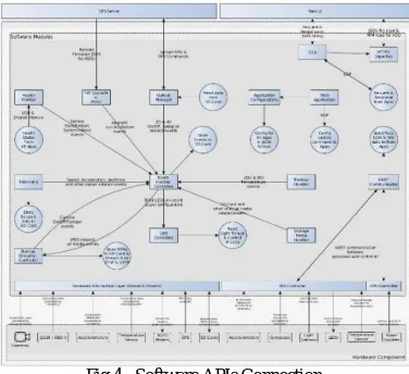
V. SOFTWARE RESOURCES
For making hardware works same as user need software part is much needed. All APIs have been made in pure embedded C language.
Fig 4. Software APIs Connection
Fig 4 shows how all the APIs are connected with each other.
LED controller: This API will help for all LED related operations. On occurrence of every specific event specific LED will glow for specific duration for specific counts.
Thermal Handler: This API will look after all temperature related activities.
Event Handler: This API will take data from tempfs and transfer it to SD card and it is also responsible for cutting down the video for specific duration on event occurrence.
Telemetry: This API will take Accelerometer, Gyroscope and all data from sensor and pass it to other APIs.
Web Application: This API will take care of Web user interface.
Upload manager: This API will take data from SD card and send it to server.
Automatic Software Download andUpgrade (ASDU): This API is responsible for downloading new firmware and uploading it in to vehicle system automatically.
Health monitor: This API will constantly ping all other APIs for their alive status. If they are working properly or not. If any API is not working properly then health monitor will restart the whole system.
Watch Dog: This API will check if health monitor is working properly or not. In case health monitor is not working and got stuck at some point. Watch dog will restart the health monitor and continuous five times if health monitor will not work then watch dog will restart the whole system.
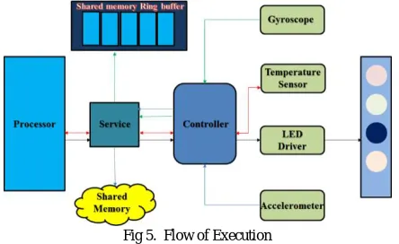
VI.FLOW OF PROCEDURE
There are typically 6 external and 2 internal cameras are installed in system as shown in Fig 2.1. All these cameras are capturing images and transfer them for further procedure. To handling all these images' frames one Audio/ Video decoder (TVP5158) is required. As here 8 cameras are there and TVP5158 has 4x1 mux. Two TVP5158 decoder chips are used. Now ultimately we have .mp4 files as an output which should be process further. Now in processor side whole firmware has been dump in to processor. In which different APIs' binaries are present. .mp4 files have been handle by storage media handler API and transfer it to temporary memory (tempfs), now after every minute all .mp4 files have been transfer from tempfs to storage (SD card) by Event Handler API. If any event occurs at that time 30 seconds of video recording is needed hence video is cutting down to 30seconds, 20 seconds before the event occurred and 10 seconds after event occurred through the same API. After that all data should be transfer from SD card to server by Upload manager API. All images and videos have been transferred from local storage to main server.
Fig 5. Flow of Execution
The main function of doing programming on microcontroller side is, It takes data at every 1 millisecond, 100 milliseconds and on other APIs request. These samples of data have been taken from sensors installed in vehicle to Shared memory to Shared memory Ring buffer and on destination APIs, and from destination APIs to main server.
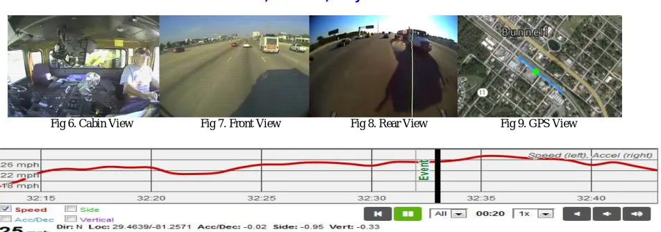
VII. RESULTS
Fig 6. Cabin View Fig 7. Front View Fig 8. Rear View Fig 9. GPS View
Fig 10. Event Generation Graph
VIII. CONCLUSION
Hence by this paper it can be concluded that this system will be very much useful of society. Detail description of each and every part of this system has been explained here in this paper. This paper is offered a user friendly interface known as web UI for monitoring the system. This system can be implement is any vehicle which stores the data in SD-card and server. It also offered live streaming of video while driver is driving the vehicle.
REFERENCES
1. "Car Black Box, Airplane technology available for cars", http://www.carblackbox.co.uk
2. “product/TMS320DM8148”, http://www.ti.com
3. “mems-accelerometer/ADXL375”, http://www.analog.com
4. “all-products/bmi055”, https://www.bosch-sensortec.com
5. “TCN75A”, http://www.microchip.com
6. “OPT3001/datasheet” http://www.ti.com
7. Chidester, Augustus, et al, "Recording Automotive Crash Event Data", International Symposium on Transportation Recorders, Arlington, VA, 1999
8. “product/MSP430FR6889/datasheet”, http://www.ti.com
9. “product/MSP430G2553”,http://www.ti.com
BIOGRAPHY
Mishrak Sharma, received B.E. degree in Electronics and Communication Engineering from L.D.R.P - I.T.R, GTU, Gandhinagar, Gujarat, India in 2012. He has successfully completed certification course in “Embedded System” from Vector India Pvt. Ltd. Bangalore, India in 2013. Currently, he is pursuing M-Tech in Embedded Systems from Ganpat University, Gujarat, India and doing Internship from eInfochips Pvt. Ltd., Ahmedabad, India.