IJEDR1602069
International Journal of Engineering Development and Research (www.ijedr.org)381
Closed Loop Topology of Converter for Variable
Speed PMSM Drive
Devang B Parmar Assistant Professor
Department of Electrical Engineering V.V.P Engineering College,Rajkot, Gujarat, India
________________________________________________________________________________________________________
Abstract- The discontinuous mode operation (DCM) of all single-switch topologies is most suitable for low power applications, somewhere these converters there outstanding characteristics of power factor correction using a very simple control scheme with only one voltage feedback loop. The Permanent Magnet Synchronous Motor is used to construct low power rating application such as Refrigerator, Washing Machine, House-hold appliances, Medical Equipment, Wide speed range of servo drives and industrial robots. CCM fly back converter sustains the same voltage stress as, but less current stress than its DCM counterpart, when delivering the same output power. As for output voltage performance, both CCM and DCM fly back converters perform equally well in terms of output voltage regulation. In the light of efficiency, the CCM fly back converter is superior to its DCM complement, which suffers from the larger conduction and switching losses.
Index Terms - Power Quality, Total Harmonic Distortion. Topology of Fly back AC-DC Converter, High Frequency Isolation, Permanent Magnet Synchronous Motor.
________________________________________________________________________________________________________
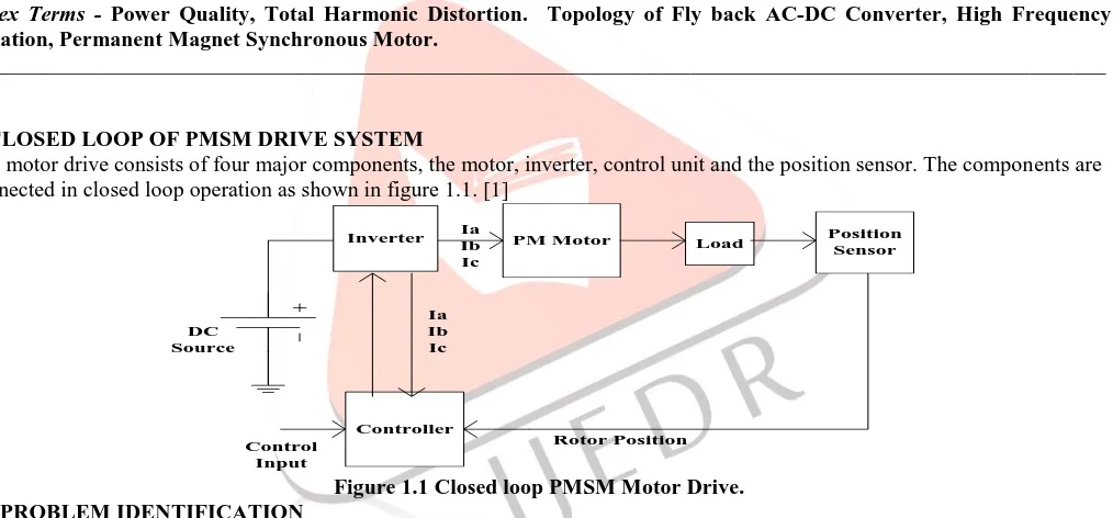
I. CLOSED LOOP OF PMSM DRIVE SYSTEM
The motor drive consists of four major components, the motor, inverter, control unit and the position sensor. The components are connected in closed loop operation as shown in figure 1.1. [1]
PM Motor
Inverter Position
Sensor
Controller
Load
Rotor Position DC
Source
Ia Ib Ic
Ia Ib Ic
Control Input
Figure 1.1 Closed loop PMSM Motor Drive. II PROBLEM IDENTIFICATION
IJEDR1602069
International Journal of Engineering Development and Research (www.ijedr.org)382
Figure 1.2 Basic Block Diagram of PMSM Drive directly connected with power supply.III MODELLING OF VECTOR CONTROLLED PMSM DRIVE SYSTEM
Figure1.2 shows the block diagram of the vector controlled PMSM drive system. It consists of control scheme with proportional plus integral (PI) speed controller, field weakening controller, d-axis current calculation, vector controller, Pulse Width Modulated (PWM) Current Controller (CC), voltage source inverter and PMSM.
1) PI speed controller: The input to the PI speed controller is the speed error
e( )
k
between reference speed ωr(k)* and the motor speed
r( )
k
. This error is estimated at the with sampling instant as:( )
( ) *
( )
e
k
rk
rk
(1)The error is processed in the PI speed controller and the output of the controller is given by the reference torque
Tk
*at kth sampling instant as:* *
( -1)
p{ ( ) -
e e( -1)}
I e( )
Tk
T k
K
k
k
K
k
(2)Where KP and KI are the proportional and integral gains of the PI speed controller, respectively. After limiting the output of the PI controller (
Tk
*) is taken as reference torque (T
ref ).2) Reference winding current generation: The quadrature, direct axis and three-phase reference motor winding currents are generated using the output of the speed controller and the rotor position. The following are the equations for the reference currents [4]:
The flux component of reference stator current (
i
d*) can be defined as: **
0
[{ - }/{ ( - )}]
d r b
d f b r r d q r b
i for and
i L L for
(3)
The torque component of the reference stator current (
i
d*) can be obtained from reference torque (Tref) as:Where Kt is motor torque constant, Ld and Lq are q-axis and d-axis inductances and
f is the flux produced by rotor magnets of PMSM. The reference three-phase currents for the stator winding can be represented as:Where
r is the rotor angular position in electrical rad/sec.IJEDR1602069
International Journal of Engineering Development and Research (www.ijedr.org)383
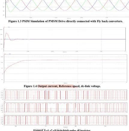
Figure 1.3 PSIM Simulation of PMSM Drive directly connected with Fly back converters.Figure 1.4 Output current, Reference speed, dc-link voltage.
Figure1.5 s1 s2 s3 switching pulse of inverter.
After Simulation and Analysis of AC-DC Fly back Converter for Variable Speed PMSM drive for Power Quality Improvement, we get Total Harmonic Distortion of Supply current is varying from 12.6212% to 6.4318% for 20% to 100% load. [7-9]. Power Factor of PMSM with Fly back Converter Connected for 20% to 100% load is 0.991 to 0.998.The design and hardware implementation of the fly back converter for 12V, 5W output has been done. The universal switching mode power supply works properly for the input range of the 85 VAC to 265 VAC.As the input voltage varies from 85 VAC to 265 VAC, the output of the fly back converter is accurately maintained at 12 V. The Controller in the Feedback Loop ensures the constant output voltage of 12 V. The circuit is designed in such a manner that it can deliver a maximum current of 400mA.
TABLE I SIMULATION PARAMETER SPECIFICATION AND INPUT DATA OF FLYBACK
CONVERTER FED PMSM DRIVE SYSTEM
Sr. No. Parameter Value
1. Input Peak Voltage (Vs) 325V
2. Output Voltage (Vdc) 120V
3. Rated Power of Converter (Pin) 900W
4. Switching Frequency of PWM Voltage Controller of Fly back Converter (fs)
50kHz 5. Rated Output Power of PMSM (Pout) 600W
6. Stator Resistance (Re) 0.195Ώ
7. Inductance d-axis (Ld) 0.45mH
8. Inductance q-axis (Lq) 0.45mH
9. Back EMF Constant (K0) 18.66V/KRPM
IJEDR1602069
International Journal of Engineering Development and Research (www.ijedr.org)384
11. Moment of Inertia (J) 0.000055Kg-m2
12. Static Friction (Tf) 0.14N-m
13. Switching Frequency of PWM Current
Controller of VSI (fc) 10kHz
14. PI Speed Controller Gains (Kp, KI) 0.9, 0.0004
DESIGN PARAMETERS OF FLYBACK CONVERTER
15 PI Voltage Controller Gain (Kpdc, Kidc) 0.3,0.03
16 Voltage Ratio ‘M’ 0.3692
17 Turn Ratio of Transformer ‘n’ 4
18 Duty Ratio ‘D’ 0.1191
19 Conduction Parameter K 0.4190
20 Critical Value of Conduction Parameter of Converter ‘Kcrit’
0.30
21 Inductance Lm’ 0.2mH
22 Filter Capacitance Cf 200nF
23 Output Capacitance Cdc 3000µF
TABLE II RESULT DATA
Sr. No %Load %THD of Is Power Factor
1 20% 9.82 0.994
2 40% 7.23 0.995
3 60% 6.57 0.996
4 80% 5.41 0.997
5 100% 4.33 0.998
IV CONCLUSION
Application of Permanent Magnet Synchronous Motor drives are used owing to its high efficiency, fast dynamic response and small size. For the operation of PMSM Drive, AC provide is converted into DC supply using rectifier path and then DC supply is converted addicted to variable magnitude and variable frequency AC supply with help of inverter to feed PMSM. High value of Total Harmonics Distortion (THD), low value of Power Factor (PF), Displacement Factor (DPF), and poor Distortion Factor (DF) are some problems of using simple rectifier circuit. These problems can be reduced by using Fly back converter. The Fly back converter be able to be use in either in CCM or DCM but if converter is used in CCM mode then it cannot sustain current stress as it can be sustained in DCM mode. PMSM operates on two modes - vector control mode and direct torque control mode. In this thesis, Simulation and Analysis of vector controlled PMSM using AC-DC Fly back Converter in DCM mode is done for power quality improvement. The single switch topologies can be preferred in sequence of fly back, Zeta, Cuk, and SEPIC converter. Because Zeta and fly back converter topologies provide additional protection beside in excess of current and inrush current as compare to Cuk and SEPIC converter topologies. Furthermore, the fly back converter topology require only a capacitor as an output filter and the Cuk converter topology requires smaller core, and has lower core and copper losses.
V REFERENCE
[1] R.Dhaouadi and N.Mohan, “Analysis of Current Regulated Voltage Source Inverters for PMSM Drives in Normal and Extended Speed Range”, IEEE Trans. on Energy Conversion, vol.5, no.1, pp.137-144, March 1990.
[2] P. Freere, P. Pillay, “Design andEvolutionof Current Controllers For PMSM Drives” 0879426004/90/1100-1193$01.00 0
1990 IEEE.
[3] C. Larouci, J.P. Ferrieux, L. Gerbaud, J. Roudet and J. Barbaroux, “Control of a fly back converter in power factor correction mode: compromise between the current constraints and the transformer volume,” in Proc. IEEE APEC, 2002, vol.2, pp. 722 – 727.
[4] Mihaela Moscalu, Petre-Daniel Ionescu, AlinMoscalu, “AC/DC Flyback converter with low switching delay” 8th International
Conference on Development And Application Systems Suceava, Romania, May 25-27,2006.
[5] C. Larouci, J.P. Ferrieux, L. Gerbaud, J. Roudet and J. Barbaroux, “Control of a flyback converter in power factor correction mode: compromize between the current constraints and the transformer volume,” in Proc. IEEE APEC, 2002, vol.2, pp. 722 – 727.
[6] B. Singh, S. Singh, A. Chandra and K. Al-Haddad, “Comprehensive Study of Single-Phase AC-DC Power Factor Corrected Converters with High Frequency Isolation,” IEEE Trans. Industrial Informatics (TII), vol. 7, no. 4, pp. 540-556, Nov. 2011. [7] P. Freere, P. Pillay, “Design And Evalution Of Current Controllers For PMSM Drives” 0879426004/90/1100-1193$01.00 0
1990 IEEE.
[8] Marian K. Kazimierczuk,”Pulse-width Modulated DC–DC Power Converters” Wright State University [5] Sanjeev Singh, Bhim Singh, “Improved Power Quality Flyback Converter fed PMBLDCM Drive” IEEE 2012.
[9] Bhim Singh, Ganesh Dutt Chaturvedi,”Comparative Performance of Isolated Forward and Flyback AC-DC Converters for Low Power Applications” IEEE 2008.
IJEDR1602069
International Journal of Engineering Development and Research (www.ijedr.org)385
[10] R. Erickson, M. Madigan and S. Singer, “Design of a Simple High-Power-Factor Rectifier Based on the Flyback Converter”,in Proc. IEEE APEC’90, 1990, pp.792-801.