PERFORMANCE ANALYSIS OF A HIGH DATA RATE UWB-DTR SYSTEM IN DENSE MULTIPATH
CHANNELS
H. Khani and P. Azmi
Electrical Engineering Department Tarbiat Modares University P.O. Box 14115-143, Tehran, Iran
Abstract—In this paper, a high data rate Ultra-Wideband Differential Transmitted-Reference (UWB-DTR) system which is one of the best and simplest available TR scheme is analyzed over IEEE 802.15.3a Channel Model 1 (CM1). We show that these systems need equalization in high data rate mode of operation because in such a case harsh nonlinear inter symbol interference (ISI) exists and degrades performance severely. The performance of the DTR system in CM1 is derived both analytically and via simulations by taking into account noise, inter path/pulse interference (IPI), and ISI. Uniform approximation for ISI distribution is proposed for the first time which gives a closer approximation than Gaussian one. All simulation and analytical results are obtained for CM1 but generalization to other channel models is also possible.
1. INTRODUCTION
Therefore, the template waveform at each rake finger must be adapted in order to be optimal. As an alternative to the complex Rake receiver for exploiting multipath diversity without channel estimation, a reference (pilot) pulse can be transmitted along with the data pulse. Time interval between pilot and corresponding data pulses must be less than the channel coherence time such that both signals experience the same channel and are distorted equally. Combining autocorrelation receiver (AcR) with UWB communication was first proposed by Immoreev and Fedotov for radar target detection purposes in [16].
The main drawback of the AcR is the lower data rate because of the transmission of reference pulses. Sending two pulses per bit instead of one, imposes an additional 3 dB performance loss and about 50% rate penalty. This performance loss is rather high, but is acceptable compared to more practical suboptimal Rake receivers, that have limited number of fingers and imperfect channel impulse response (CIR) estimation in the presence of path dependent pulse distortion [12] and angle dependent responses of transmit/receive antennas [13].
In order to double data rate and to reduce ISI in conjunction with a 3 dB gain in performance, the DTR scheme can be employed. The DTR scheme was first proposed in [20] which is a modification of the TR system [21–23] in this, instead of transmitting a separate pulse, the data are differentially modulated using previously sent pulses. In this paper performance analysis of the high data rate UWB-DTR system in dense multipath channels is done both analytically and via simulations by taking into account noise, IPI, and ISI. Also, probability of error (POE) performance is derived in terms of SNR over CM1. Both uniform and Gaussian approximations for ISI is considered which the former gives a closer approximation than the latter. It is shown that in the DTR system, ISI term is not zero-mean which confirms the results obtained in [12, 24, 25]. Simulation results show that integration interval has a great influence on the receiver performance.
2. UWB-DTR SYSTEM
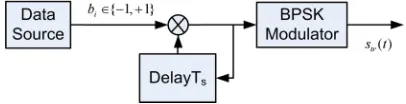
In this section, the signal model is given for the UWB-DTR scheme. We employ BPSK modulation scheme throughout this paper because it outperforms the BPPM one [26], furthermore it removes spectral spikes which leads to a smooth spectrum and as a result the BPSK-UWB-DTR scheme can easily meet the FCC imposed spectral masks on the UWB spectrum [27].
Figure 1. The block diagram of the UWB-DTR transmitter.
2.1. Transmitted Signal Model
Each data symbol {bi} ∈ B = {−1,+1}, i denoting the bit index, is differentially modulated using pulse polarities di =bidi−1. The block
diagram of the UWB-DTR transmitter is illustrated in Fig. 1. The transmitted signal in this scheme is written as:
str(t) =
∞
i=−∞
diwtr(t−iTs) (1)
where wtr(t) is the transmitted pulse shape with normalized energy, and Ts is the symbol duration. Fig. 2 shows a typical signaling of the UWB-DTR system. Herein, we assume that the channel changes very slowly in comparison with the symbol duration,Ts; this assumption is suitable for UWB indoor applications in which users’ maximum speed is negligible.
Figure 3. The block diagram of the UWB-DTR receiver.
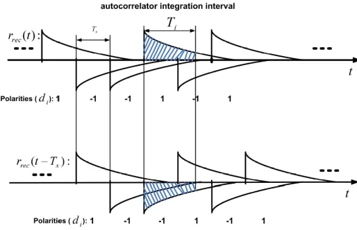
Figure 4. Illustration of the contribution of previous and subsequent interfering pulses on the correlation result.
2.2. Received Signal Model
The block diagram of the UWB-DTR receiver structure is shown in Fig. 3. The transmitted signal is passed through multipath channel c(t) and is corrupted by additive white Gaussian noise (AWGN),n(t). Therefore, the following signal is received (see Fig. 4):
rrec(t) =
∞
i=−∞
diwtr(t−iTs)∗c(t) +n(t)
=
∞
i=−∞
dih(t−iTs) +n(t) (2)
where * denotes linear convolution,h(t) =wtr(t)∗c(t), andn(t) is the receiver thermal noise with two sided power spectral density N0
2 . Then,
The signal at the output of this filter is as follows:
r(t) =
∞
i=−∞
diwtr(t−iTs−τ) +v(t)
= s(t−τ) +v(t) (3)
where g(t) = wtr(t)∗c(t)∗f(t), s(t) is the received noise-free signal which corresponds tosrec(t) in (2), v(t) =n(t)∗f(t), and τ represents the time delay between transmitter and receiver.
Without loss of generality, we can assume that τ = 0 in order to simplify the notation. The above signal is multiplied by its Ts seconds delayed replica and is integrated and sampled. Integration is performed over a time interval Ti, which can be properly chosen to optimize the performance [28–30]. In this paper, the optimum value forTi is obtained numerically and it is shown that its optimum value is not greater than the symbol interval, i.e., Ti ≤ Ts. The output of the AcR is sampled at the symbol rate. Thus, the output of AcR for thekth symbol is given by:
z[k] = Ti
0
r(t+kTs)r(t+ (k−1)Ts)dt (4)
To reach an analytically tractable channel model, the total number of multipath components is defined as the number of multipath arrivals with expected power within 10 dB from that of the strongest arrival. As a result the channel impulse response can be simplified to c(t) =
L
n=0αnδ(t−τn). In IEEE 802.15.3a CM1 which is used in this paper,
the Rayleigh distribution in the S-V channel model is replaced by the lognormal distribution. In this paper, in order to include IPI, the channel impulse response is normalized instead of the received signal, i.e., Ln=0|αn|2 = 1. Replacing (3) into (4) yields:
z[k] =s[k] +v1[k] +v2[k] +v3[k] (5)
where
s[k] = Ti
0
s(t+kTs)s(t+ (k−1)Ts)dt (6)
v1[k] =
Ti
0
v2[k] =
Ti
0
v(t+kTs)s(t+ (k−1)Ts)dt (8)
v3[k] =
Ti
0
v(t+kTs)v(t+ (k−1)Ts)dt (9)
In order to derive the equivalent system model, first the receiver is analyzed in the noise-free state in Section 3. Next, noise is included in Section 4.
3. UWB-DTR EQUIVALENT SYSTEM MODEL WITHOUT NOISE
Using the above mathematical definitions, in this case the received bandpass filtered signal can be written as:
r(t) =s(t) =
∞
i=−∞
dig(t−iTs) (10)
where g(t) = wtr(t) ∗ c(t) ∗ f(t) is the response of the equivalent channel (including the receiver’s front-end filter) to the transmitted pulse. Replacing (10) into (6) yields:
s[k] =
Ti
0
n
i=−m
dk+ig(t−iTs)
n
j=−m
dk+j−1g(t−jTs)dt (11)
where m = Td/Ts −1 and n = Ti/Ts −1 denote the number of previous and subsequent interfering pulses, respectively. Herein, Td represents the multipath delay spread of the channel. Equation (11) can be rewritten as:
s[k] = n
i=−m n
j=−m
dk+idk+j−1Pi,j (12)
where
Pi,j =
Ti
0
pulses on the correlation result. In a compact matrix notation, (12) can be rewritten as follows:
s[k] =dkLTdTk−1 =dkLdTk−1 (14)
which represents the polarities of pulses and the last term in (14) is obtained by using the symmetric property of matrix L resulted from its definition in (16). Using (13), the elements of this (m+n+ 1)× (m+n+ 1) matrix are given by:
[L]i,j =Pi−m−1,j−m−1 (15)
for all i, j ∈ {1,2,3, . . . , m +n+ 1}. This matrix illustrates the channel response including any linear filtering, pulse distortion, and inter path/pulse interference (IPI).
4. UWB-DTR EQUIVALENT SYSTEM MODEL WITH NOISE
According to (5), two “linear” noise terms v1[k] and v2[k], which
depend on the received bandpass filtered signal s(t), and a “product” noise termv3[k] contribute to the decision statistic.
Following [12, 24, 31, 32], and [33], we assume that all three noise terms at the AcR output are zero-mean Gaussian distributed random variables, provided that v(t) is zero-mean, and that the product of noise bandwidth by integration intervalW Ti 1, where a product of
≥20 gives an accurate approximation [34].
The noise terms of the decision variablez[k] is denoted byN[k] = z[k]−s[k]. Employing (5) and taking into account thatE{N[k]}= 0, the following expression for the variance ofN[k] is obtained:
σN2 = 2 n
i=−m
Ti
0
Ti
0
g(t−iTs)g(τ−iTs)Rn(t−τ)dtdτ
+N0
Ti
Ts n
i=−m
g(t−(i+2)Ts)gi(t)dt+
Ti
0
Ti
0
R2v(t−τ)dtdτ(16)
in which Rv(τ) = E{v(t + τ)v(t)} represents the autocorrelation function ofv(t). Using some approximations, (16) can be approximated as:
σ2N ∼=N0
n
i=−m
Ei+N0
n−1
i=−m Ki+
N02W Ti
whereKi is defined as:
Ki =
Ti
Ts
g(t−(i+ 2)Ts)gi(t)dt (18)
and Ei=
∞
−∞g
2
i(t)dt denotes the energy ofgi(t) which is defined as:
gi(t) =g(t−iTs)U(Ti−t)U(t) (19) in which U(t)represents the unit step function. The ISI term in (12) that is independent of noise process equals:
ISI[k] = n
i=−m,i=0
n
j=−m
dk+idk+j−1Pi,j+
n
j=−m,j=0
dkdk+j−1P0,j (20)
The mean of ISI[k] is given as:
µISI[k]= n−1
i=−m,i=0
Pi,i+1+U[n−1]P0,1 (21)
whereU[n] is the discrete unit step function. Therefore, in the UWB-DTR system ISI[k] does not depend on k and is not zero mean [12, 24, 25]. Omitting index k, and using (20) and (21) the variance of ISI is obtained as:
σISI2 = n
i=−m,i=0
n
j=−m Pi,j2 +
n−1
i=−m,i=0
n−1
i=−m,i=0
Pi,i+1Pi,i+1−2
n−1
i=−m,i=0
Pi,i2+1
+2U[n−1]
n−1
i=−m,i=0,i=−1
Pi,1P0,i+1+
n
i=−m,i=0,i=1
P02.j (22)
Assuming equally likely bits and Gaussian distribution for both ISI and noise, the probability of error (POE) for the UWB-DTR system, is obtained for a given channel realization, as:
Pe=Q
P0,0+µISI
σN2 +σ2ISI
(23)
5. RESULTS AND DISCUSSIONS
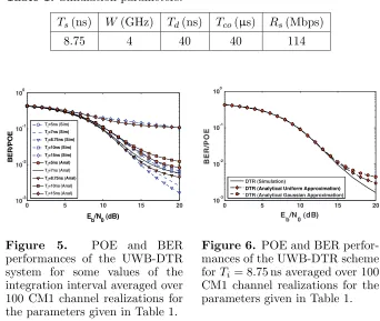
scheme using both Gaussian and uniform approximations for ISI. For simulating multipath channel, IEEE 802.15.3a Channel Model 1 (CM1) is considered. We assume fully coherent detection for obtaining numerical and analytical results. A second order derivative Gaussian monopulse with τ = 0.2877 ns has been used for wtr(t), i.e., wtr(t) = [1−4π(t/τ)2] exp(−2π(t/τ)2). Fig. 5 shows both analytical POE and simulated BER performances of the DTR scheme versusEb/N0 in dB
for some values of the integration interval, i.e., Ti. The simulation parameters are given in Table 1. As seen from Fig. 5, the best value for the integration interval in the DTR system obtained from both numerical and simulation results isTi =Ts= 8.75 ns. Fig. 5 illustrates that the performance of the AcR in the DTR scheme is too susceptible to the integration interval.
Table 1. Simulation parameters.
Ts(ns) W(GHz) Td(ns) Tco(µs) Rs(Mbps)
8.75 4 40 40 114
0 5 10 15 20
10-3 10-2 10-1 100
Eb/N0 (dB)
BE R/ P O E T
i=5ns (Sim)
T
i=7ns (Sim)
Ti=8.75ns (Sim)
T
i=10ns (Sim)
Ti=15ns (Sim)
Ti=5ns (Anal) T
i=7ns (Anal)
Ti=8.75ns (Anal) T
i=10ns (Anal)
T
i=15ns (Anal)
Figure 5. POE and BER performances of the UWB-DTR system for some values of the integration interval averaged over 100 CM1 channel realizations for the parameters given in Table 1.
0 5 10 15 20
10-3 10-2 10-1 100
E b/N0 (dB)
BER/
P
O
E
DTR (Simulation)
DTR (Analytical Uniform Approximation) DTR (Analytical Gaussian Approximation)
Figure 6. POE and BER perfor-mances of the UWB-DTR scheme forTi= 8.75 ns averaged over 100 CM1 channel realizations for the parameters given in Table 1.
It is seen that uniform approximation for ISI distribution gives a better approximation than Gaussian one. Fig. 6 shows that Gaussian approximation for ISI distribution is too pessimistic and gives a weak upper bounds for POE.
6. CONCLUSIONS
In this paper, performance of the UWB-DTR communication system was analyzed. It was shown that in high data rate UWB-DTR harsh nonlinear ISI degrades performance severely. It was also shown that the UWB-DTR scheme was too susceptible against small changes in the integration interval. It was observed that Uniform approximation for ISI gives a better and closer approximation.
REFERENCES
1. Kolenchery, S. S., J. K. Townsend, and J. A. Freebersyser, “A novel impulse radio network for tactical military wireless communications,” Proc. Military Comm. Conf., Vol. 2, 59–65, Oct. 1998.
2. Win, M. Z., X. Qiu, R. A. Scholtz, and V. O. K. Li, “ATM-based TH SSMA network for multimedia PCS,” IEEE JSAC, Vol. 17, No. 5, 824–836, May 1999.
3. Aiello, G. R., G. D. Rogerson, R. A. Scholtz, and V. O. K. Li, “Ultrawideband wireless systems,” IEEE Microwave Magazine, Vol. 4, No. 2, 36–47, Jun. 2003.
4. Withington, P., H. Fluhler, and S. Nag, “Enhancing homeland security with advanced UWB sensors,” IEEE Microwave
Magazine, Vol. 4, No. 3, 51–58, Sep. 2003.
5. Win, M. Z. and R. A. Scholtz, “Ultra-wide bandwidth time-hopping spread-spectrum impulse radio for wireless multiple-access communications,” IEEE Trans. Commun., Vol. 48, No. 4, 679–691, Apr. 2000.
6. Chen, F. C. and W. C. Chew, “Time-domain ultra-wideband microwave imaging radar system,” Journal of Electromagnetic
Waves and Applications, Vol. 17, 313–331, 2003.
8. Lie, J. P., B. P. Ng, and C. M. See, “Multiple UWB emitters DOA estimation employing time hopping spread spectrum,”Progress In
Electromagnetics Research, PIER 78, 83–101, 2008.
9. Jeong, Y. S. and J.-H. Lee, “Estimation of time delay using conventional beam forming-based algorithm for UWB systems,”
Journal of Electromagnetic Waves and Applications, Vol. 21,
No. 15, 2413–2420, 2007.
10. Soliman, M. S., T. Morimoto, and Z.-I. Kawasaki, “Three-dimensional localization system for impulsive noise sources using ultra-wideband digital interferometer technique,” Journal of
Electromagnetic Waves and Applications, Vol. 20, No. 4, 515–530,
2006.
11. Win, M. Z. and R. A. Scholtz, “On the energy capture of ultrawide bandwidth signals in dense multipath environments,”
IEEE Commun. Lett., Vol. 2, No. 9, 245–247, Sep. 1998.
12. Romme, J. and K. Witrisal, “Transmitted-reference UWB systems using weighted autocorre-lation receivers,” IEEE Trans.
on Microwave Theory and Techniques, Vol. 54, No. 4, 1754–1761,
Apr. 2006.
13. Siwiak, K. and D. McKeown, Ultra-Wideband Radio Technology, John Wiley & Sons, 2004.
14. Ramirez-Mireles, F., “On the performance of ultra wideband signals in gaussian noise and dense multipath,” IEEE Trans. on
Veh. Tech., Vol. 50, No. 4, 244–249, Jan. 2001.
15. Taylor, J. D., Intruduction to Ultra-Wideband Systems, CRC Press, Ann Arbor, 1995.
16. Taylor, J. D.,Ultra-Wideband Radar Technology, CRC Press, New York, 2001.
17. Chen, C.-H., C.-H. Liu, C.-C. Chiu, and T.-M. Hu, “Ultrawide band channel caculation by SBR/IMAG techniques for indoor communication,” Journal of Electromagnetic Waves and
Appli-cations, Vol. 20, No. 1, 41–51, 2006.
18. Liu, Y. J., Y. R. Zhang, and W. Cao, “A novel approach to the refraction propagation characterisitcs of UWB signal waveforms,”
Journal of Electromagnetic Waves and Applications, Vol. 21,
No. 14, 1939–1950, 2007.
19. Liu, X. F., B. Z. Wang, S. Xiao, and J. H. Deng, “Performance of impulse radio UWB communications based on time reversal technique,”Progress In Electromagnetics Research, PIER 79, 401– 413, 2008.
receivers for ultra-wideband transmitted reference systems,”Proc.
GLOBECOM03, Vol. 2, 759–763, San Francisco, CA, Dec. 2003.
21. Xiao, S., J. Chen, F. Liu, and B. Z. Wang, “Spatial focusing characteristics of time reversal UWB pulse transmission with different antenna arrays,” Progress In Electromagnetics Research B, Vol. 2, 223–232, 2008.
22. Chen, X., “Time-reversal operator for a small sphere in electromagnetic fields,” Journal of Electromagnetic Waves and
Applications, Vol. 21, 1219–1230, 2007.
23. Xiao, S., J. Chen, B.-Z. Wang, and X.-F. Liu, “A numerical study on time-reversal electromagnetic wave for indoor ultrawideband signal transmission,” Progress In Electromagnetics Research, PIER 77, 329–342, 2007.
24. Pausini, M., G. J. M. Janssen, and K. Witrisal, “Performance enhancement of differential UWB autocorrelation receivers under ISI,”IEEE JSAC, Vol. 24, No. 4, 815–821, Apr. 2006.
25. Witrisal, K., G. Leus, M. Pausini, and C. Krall, “Equivalent system model and equalization of differential impulse radio uwb systems,”IEEE JSAC, Vol. 23, No. 9, 1851–1862, Sep. 2005. 26. Khani, H. and P. Azmi, “Performance analysis of TH-UWB
radio systems using proper waveform design in the presence of narrow-band interference,” Wiley European Transactions on
Telecommunications-ETT, Vol. 17, 111–123, Feb. 2006.
27. Revision of Part 15 of the commission’s rules regarding ultra-wideband transmission systems, FIRST REPORT AND ORDER, Federal Communications Commission, Feb. 14, 2002.
28. Zasowski, T., F. Althaus, and A. Wittneben, “An energy effi-cient transmitted-reference scheme for ultra wideband communi-cations,”Proc. of IEEE Joint UWBST&IWUWBS, 146–150, 2004. 29. Franz, S. and U. Mitra, “Integration interval optimization and performance analysis for UWB transmitted reference systems,”
IEEE International Workshop on Ultra Wideband Systems Joint with Conference on Ultrawideband Systems and Technologies,
Joint UWBST & IWUWBS, 26–30, May 2004.
30. Romme, J. and K. Witrisal, “Oversampled weighted autocorre-lation receivers for transmitted-reference UWB systems,” IEEE
61st VTC 2005-Spring, Vol. 2, 1375–1380, Stockholm, Sweden,
June 2005.
32. Choi, J. and W. Stark, “Performance of ultra-wideband commu-nications with suboptimal receivers in multipath channels,”IEEE JSAC, Vol. 20, No. 9, 1754–1766, Dec. 2002.
33. Quek, T. Q. S. and M. Z. Win, “Analysis of UWB transmitted-reference communication systems in dense multipath channels,”
IEEE JSAC, Vol. 23, No. 10, 1863–1874, Sep. 2005.