A Small Aperture Direction Finding System with Beamforming
and Null Steering Capability
Sek-Meng Sow* and Tan-Huat Chio
Abstract—A Direction Finding (DF) algorithm for small aperture DF systems is proposed. Traditionally, small aperture DF systems lack beamforming capabilities and therefore require manual rotation, which may affect the Angle of Arrival (AOA) estimation accuracy. Based on Characteristic Mode (CM) Analysis, a Multi-Feed Structural Antenna (MFSA) is developed that utilizes an electrically small platform as a radiator. This paper chooses a Small Unmanned Aerial Vehicle (SUAV) as a design platform. The overlap of all Individual Element Radiation Patterns (IERPs) of the proposed MFSA covers the entire azimuth plane. In this way, beamforming and null steering of the MFSA on the azimuth plane can be achieved by linearly combining all weighted IERPs. A new method based on Vector Singular Value Decomposition (SVD) is proposed to determine the weight vector of beamforming (“Sum” pattern) and null steering (“Difference” pattern) in a specific direction. Based on the “Sum-Difference” delta method, the AOA of the Radio Frequency (RF) signal source can be estimated. A small aperture VHF DF system with a multi-channel digital-IF receiver is developed to experimentally verify the proposed concept. The evaluation results show that the AOA estimation RMS error is 1.55◦, and the false detection rate is significantly improved.
1. INTRODUCTION
A Radio Direction Finding (RDF) system is defined as a system that estimates the Angle of Arrival (AOA) of an incoming signal [1]. Since the First World War and World War II, it has been widely used to provide electronic military intelligent information from the air and at sea. In addition, it was used for aircraft and maritime navigation before the implementation of Global Positioning System (GPS) for civilian usage in 1980’s. However, even today, there are many other modern tasks that required DF systems, such as search and rescue missions, wildlife tracking, location radio marker, spectrum monitoring and interference signal tracking, to name but a few.
In general, the DF system can be classified by the linear aperture size (or maximum linear dimension) of the antenna system used. Basically, there are three classes, namely small-aperture, medium-aperture, and large-aperture DF systems [1]. In [1], the linear aperture size of an antenna system used in a small-aperture DF system should be less than 0.8λ; for medium- and large-aperture DF systems, the size of the antenna system should be “0.3λ to 2λ” and “1λ to 100λ”, respectively. For example, the Multiple Antenna System (MAS) used in small-aperture DF system can be a 2 or 4×λ/2 dipole or a full-size circular loop with diameter of λ/π (also known as Adcock Antennas [2]); a linear antenna array or a circular antenna array is used for the medium-aperture DF; and a shaped reflector or an electrically large array with directional beam pattern is used for the large-aperture DF system. In addition, there are several computational methods that can be used to extract the AOA information of the received source signal through the DF systems. These methods are Amplitude ratio, Phase Comparison (or Doppler techniques) and Time Delay [1]. However, Phase Comparison and
Received 4 December 2018, Accepted 16 January 2019, Scheduled 4 March 2019
* Corresponding author: Sek-Meng Sow ([email protected]).
Time Delay methods require the use of complex antenna systems, such as multiple-directional antenna systems or large antenna arrays. Therefore, small aperture DF systems typically use Amplitude ratio or the Watson-Watt method [1] to estimate AOA. The Watson-Watt method obtains AOA information based on the amplitude difference of two antennas having orthogonal radiation patterns, such as a crossed loop (or dipole) antenna. Due to the symmetrical nature in the radiation pattern, there is an ambiguity of 180◦ in the estimation result. In this case, an additional omnidirectional receiving antenna is required. Furthermore, the larger the amplitude ratio changes with respect to the bearing angle, the higher the accuracy of the estimated AOA is. In order to improve the accuracy and provide a wider angular coverage, a rotation mechanism is required. It can be implemented mechanically (for example, a turntable) or electrically (for example, a phased antenna array. Again, these solutions are not feasible for small-aperture DF systems. Therefore, the rotation of this type of DF system is achieved by manually rotating the antenna system, which may introduce uncertainty in the AOA estimation. Therefore, the AOA estimation RMS error of such a DF system is usually as high as 6.1◦ [3].
Furthermore, existing MASs for small-aperture DF systems are difficult to install on portable platforms, especially when the platform size is comparable to the operating wavelength. For example, the VHF DF system on a small Unmanned Aerial Vehicle (SUAV) has a maximum size of 2 m. In this paper, a complete solution is proposed for such an operating environment. The proposed DF system includes a Multi-Feed Structural Antenna (MFSA) on SUAV as a MAS with a digital IF receiver and is described in Section 2.1 and Section 2.2. In Section 2.3, a new mathematical method is introduced to determine the required weight vectors for beamforming (“Sum”) and null steering (“Difference”) of the MAS radiation pattern in the specified direction. By exploiting the ability of beamforming and null steering, the Amplitude Comparison method or the “Sum-Difference” delta method can be used to estimate the AOA of the incoming signal. The experimental results of the proposed DF system are discussed in Section 3. Finally, Section 4 summarizes this paper.
2. PROPOSED SMALL-APERTURE DIRECTION FINDING (DF) SYSTEM
As described in the previous section, the proposed small-aperture DF system includes a 4-feed antenna system and a 4-channel digital-IF receiver. The hardware block diagram of the proposed DF system is shown in Fig. 1, and each subsystem is described in Section 2.1 and Section 2.2. Since the proposed DF
algorithm is based on the Amplitude Comparison method, it is necessary to synthesize the “Sum” and “Difference” patterns of the MAS in the specified direction. In order to synthesize the desired radiation pattern, all weighted IERPs of the MAS can be linearly combined. However, determining the weight vector required for “Sum” and “Difference” pattern based on the Least Square Error (LSE) method requires the use of different constraints, which may make it difficult to provide any physical justification of the selection. To overcome this problem, a new weight vector estimation method is suggested and described in Section 2.3.
2.1. Proposed Multi-Feed Antenna Design on SUAV
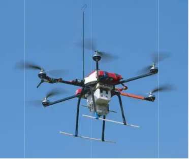
For the SUAV platform, in order to be able to install an antenna of comparable dimension to it, a λ/4 monopole or a whip antenna is widely used, but it may protrude from the platform, as shown in Fig. 2. As such, the aerodynamic performance of the SUAV may be impaired. To overcome this problem, if the surface of the entire platform is electrically conductive, the platform can be used as a radiator. Here, Characteristic Mode (CM) Analysis [4] is suggested as an analytical tool for designing MAS integrated in the SUAV platform.
Figure 2. An example of a SUAV with protruded antenna installed.
The basic design flow of a MAS using CM Analysis is as follows. If the appropriated CM is not identified in step2, the designer needs to return to step1 and redefines the design platform, or concludes that the selected platform is not suitable for designing the antenna based on CM Analysis.
1. Define the design platform.
2. Perform CM Analysis on the defined platform.
3. CM selection.
4. Determine the location and type of feed based on the Selected CMs.
5. Feed design.
6. MAS performance verification.
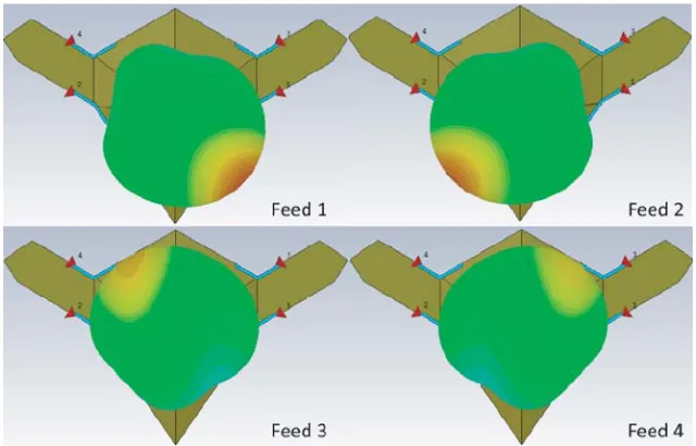
The final MAS design on the selected SUAV model is a 4-feed antenna system with an Inductive Coupling Element (ICE) selected as its feeds (as shown in Fig. 3). The Individual Element Radiation Pattern (IERP) for each feed is shown in Fig. 4. For the sake of brevity, the design details of this MAS design will not be described here and should be provided in [5].
2.2. 4-Channel Digital IF Receiver
Figure 3. A 4-feed antenna system on the selected SUAV platform and its Inductive Coupling Element (ICE) design.
Figure 4. Individual Element Radiation Patterns for Feed 1∼4 of the proposed MAS.
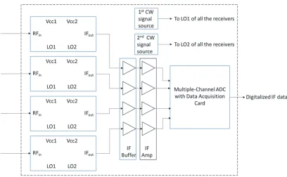
is designed to digitize the measured signal vector and then process the digitalized data through the proposed DF algorithm (see Section 3) to extract the AOA information of the measured signal. A system block diagram of the proposed Digital IF receiver is shown in Fig. 5. The multi-channel receiver is based on the commercially off-the-shelf (COTS) components, which consists of a 4× single channel receiver (using the NXP chipset, consisting of SA602 [6] and SA605 [7]), a 2×local oscillator (LO) source, a 4×channel IF buffer (AD8244, [8]), a 4×channel IF amplifier (ZFL-500LN+ [9]), and multi-channel ADC (AD9249-65 [10]) with data acquisition card (HSC-ADC-EVALDZ [11]).
Figure 5. A block diagram of the 4-channel digital-IF coherent receiver.
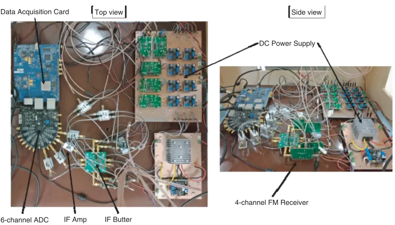
the measured IF phase differences are from −2.3◦ to −13.1◦ and 1.0◦ to 3.7◦, respectively. The mean of the measured phase difference is known as the deterministic quantity and can be compensated by system calibration. However, it is impossible to eliminate random variations, which are measured as the standard deviation,σ, of the phase difference. To understand the effect of this random variation on the synthesized radiation pattern, a statistical study is performed by manually introducing simulated phase noise to the weight vector. A synthesized radiation pattern obtained by linearly combining four IERPs with a weight vector, w, of {0◦,180◦,0◦,180◦} is used for this study. By adding phase noise to each phase setting of wbased on the Monte Carlo Simulation method [12], the observed maximum peak gain variations when σ = 3◦ and σ = 5◦ are 0.08 dB and 0.37 dB, respectively. In general, variations in the peak gain of the measured radiation pattern of less than 0.1 dB are considered to be negligible. Therefore, the standard deviation of the phase difference <3◦ should be acceptable. As such, all single channel receivers except T2 are qualified to be used for the proposed multi-channel Digital IF receiver (as shown in Fig. 6).
Table 1. Test results for the 6 single-channel receivers.
Receiver Current 12 dB SINAD IF output (w.r.t. TI)
Amp Imbalance Phase Difference
mA dBm dB Mean (◦) Std Dev (◦)
T1 7.4 −104.0 - -
-T2 7.4 −104.0 −0.3 −13.1 3.7
T3 7.4 −104.0 0.7 −4.7 2.1
B1 7.5 −105.0 0.3 −10.5 2.1
B2 7.4 −104.3 0.1 −2.3 1.6
Data Acquisition Card Top view Side view
DC Power Supply
16-channel ADC IF Amp IF Butter
4-channel FM Receiver
Figure 6. The complete 4-channel Digital-IF coherent receiver.
2.3. Proposed Weight Vector Estimation Method
Since the resulting radiation pattern of a MAS can be obtained by linearly combining all weighted IERPs, the “Sum” (beamforming) and “Difference” (null steering) pattern for any given direction can be obtained if the required weight vectors are known. Generally, the required weight vector, w, is determined by solving the vector equation stated as Eq. (1) with some constraints, whereIERP is the pattern vector, andF is the resulting radiation pattern. This is also known as the Least Square Error (LSE) method.
F(r,θ) =−−−−→IERP(r, θ) w (1)
The LSE method is well suited for determining the weight vector, wsum, to synthesize the “Sum” pattern in the specified direction,θ, which can be done by simply defining a fairly large value forF. However, this is not the case of determining the weight vector, wdiff, for null steering by simply set F = 0. By doing so, it can result in wdiff to be a null vector. In order to prevent yielding of a null vector as a result, at least one element of wdiff needs to be specified as a constant value. Theoretically, there should be an infinite way to define constraints for determining the weight vector using the LSE method. It is also difficult to provide a physical explanation for the constraints. Furthermore, two mathematical operations are required to determine the weight vectors for “Sum” and “Difference” patterns in the specified direction, θ.
Here, a vector Singular Value Decomposition (SVD) method is proposed for determining all required weight vectors in a single operation. Physically, the weight vector, wsum, that maximizes the field (or the “Sum” pattern) in the specified direction,θ, can be considered as a complex conjugate of the pattern vector, IERP (θ). On the other hand, the weight vector, wdiff, for the null steering (or “Difference” pattern) can be viewed as a vector orthogonal toIERP (θ). Thus, by performing the vector SVD on the pattern vector,IERP (θ), one weight vector of the “Sum” pattern and (n−1) orthogonal weight vectors of the “Difference” pattern in θ direction can be obtained. The formula of the vector SVD method is stated in Eq. (2), where wsum=v1 and wdiff =vi fori= 2 to n.
−−−−→
IERP(θ)1×n = uS1×n[V]Tn×n
= [ λ1 0 . . . 0 ]1×n[ v1 v2 . . . vn ]Tn×n (2)
direction based on the measured signal vector, it should be less susceptible to noise. In Section 3, this is verified by comparing the AOA estimation measurements obtained by the two methods, the LSE method and the vector SVD method.
3. EXPERIMENTAL RESULTS DISCUSSION
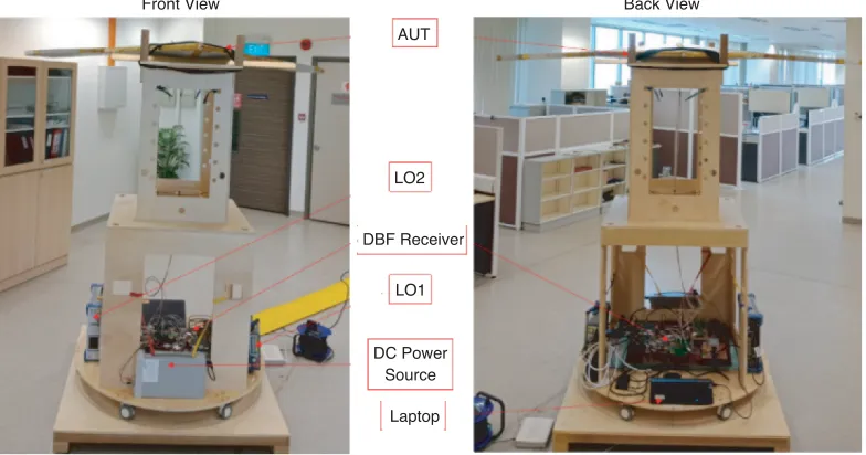
Based on the hardware description provided in Section 2, a VHF DF system for the SUAV prototype is constructed, as shown in Fig. 7. For measurement purpose, it can be seen in Fig. 7 that the entire DF system is placed on a wooden rotatable platform. The DF test setup is depicted in Fig. 8. The signal source is located 6 m away from the Unit Under Test (UUT), which is equivalent to 2.3λ@115 MHz (where the far field radiation region of 115 MHz should be>1.2λ). This setup can be used to emulate signal sources from different directions by rotating the UUT. Thus, the IERP of the MAS can be measured. Due to the limitations of the test facility, these IERPs are only measured on the azimuth plane. Therefore, the following discussion is limited to 1D AOA estimation on the azimuth plane. However, this should not limit the proposed DF algorithm. In general, if 3D IERPs are available, it can also be used for 2D AOA estimation applications. A MATLAB code for this algorithm has been developed to estimate the AOA and control the turntable.
Front View Back View
AUT
LO2
DBF Receiver
LO1
DC Power Source
Laptop
Figure 7. A VHF DF system for a SUAV prototype.
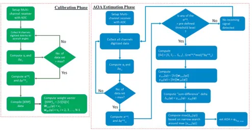
The proposed DF algorithm consists of two phases, a Calibration Phase and an AOA Estimation Phase. A flow chart of the proposed algorithm is shown in Fig. 9. During the Calibration Phase, the IERP of all feeds in the MAS is measured, as shown in Fig. 10. Based on these IERPs, wsum and wdiff are computed based on the selected method (LSE method or vector SVD method). Once all the
required weight vectors have been computed for the entire azimuth plane, the DF system is considered to be calibrated and should be ready for AOA estimation. For verification purposes, the UUT is rotated in the azimuth plane from −180◦ to 180◦ in 1◦ step (where the nose of the SUAV is referred as 0◦ in the azimuth plane), and the DF system measures the signal received by the MAS, then based on the “Sum-Difference” delta method extracts the embedded AOA information. An example screen shot of an AOA estimation with a signal source at 0◦ is shown in Fig. 11.
Basically, the performance of the proposed VHF digital DF system is evaluated based on the following criteria,
1) the overall root mean square (RMS) error of the estimated AOAs, 2) the mean error value of the estimated AOAs,
Figure 8. The Direction Finding test setup.
Figure 9. The process flow chart of the proposed DF algorithm.
4) the false-detection rate.
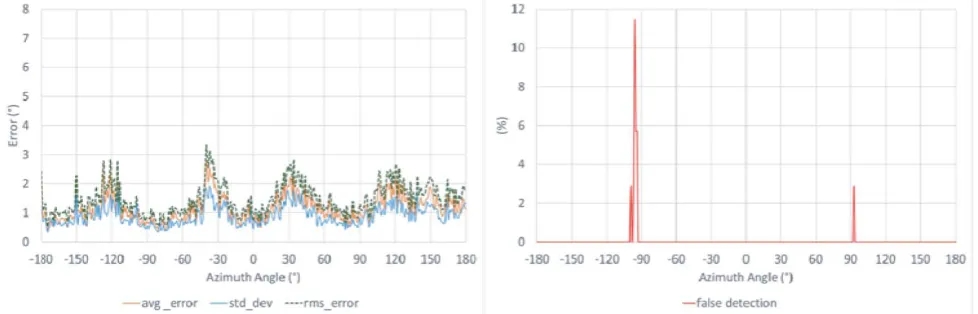
Here, the overall RMS error is defined as the RMS average of all estimated AOA values over the selected azimuth range [13], and “false-detection” is defined as the occurrence of an estimation error > 10◦. To compare the performance of two different weight vector determination methods, the LSE method and vector SVD method, each method collects a total of 35 sets of AOA estimation data. Statistical processing is performed on these data. For LSE and vector SVD, statistical results (such as rms, mean, and standard deviation) of AOA estimation error and false detection rate are shown in Fig. 12 and Fig. 13, respectively.
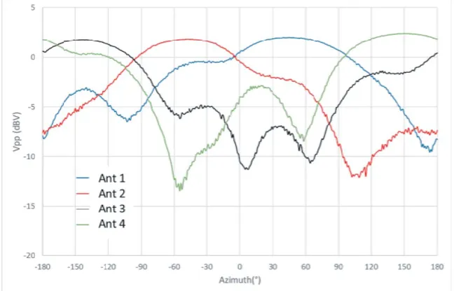
Figure 10. Measured IERPs for all feed elements of the proposed MAS.
Figure 11. A computer screenshot displays the result of an estimated AOA with reference to the UUT.
Figure 13. The rms, mean and standard deviation of AOA estimation error and the false-detection rate over the entire azimuth plane based on 35 sets of estimated AOA data based on the weight determined by Vector SVD method.
for the LSE method and SVD method, the overall RMS error values are computed to be 2.67◦ and 1.55◦, respectively. This indicates that the performance of the latter over the entire azimuthal plane is 42% better than the former. This also shows that the “Difference” pattern synthesized using multiple orthogonal weight vectors is less susceptible to phase noise variations in the measured signal vector. In other words, the SVD method provides a higher possibility of synthesizing a “Difference” pattern with “deeper” null even under the influence of system noise. As such, it has a lower false-detection rate than the LSE method. In general, the maximum false-detection rate recorded is less than 12%, so the performance of the proposed DF system should be considered acceptable. Furthermore, given the overall RMS estimation error of 1.55◦, the proposed small-aperture DF system is qualified as a class B DF system [14], where most of the commercial small aperture DF systems (using 5-element small based antenna system with Amplitude Comparison techniques) are classified as class D DF systems because their typical overall RMS estimation error is 6.1◦ [3, 15].
4. CONCLUSIONS
The VHF DF system on the SUAV prototype is developed to experimentally verify the performance of the proposed MAS and the proposed weight vector estimation method in Direction Finding (DF) applications. The MAS is designed based on Characteristic Mode (CM) Analysis, and the vector SVD method is proposed to derive all required weight vectors for the synthesis of one “Sum” and multiple “Difference” patterns. Overall, the AOA estimation performance of the proposed system indicates that the vector SVD method has a lower rms estimation error and a significant improvement in the false detection rate compared to the LSE method.
ACKNOWLEDGMENT
Here, the authors would like to thank Mr. Tan Peng Khiang and Mr. Dylan Ang, members of the antenna group technical support team of Temasek Laboratories @ National University of Singapore, for their innovative ideas and suggestions during the prototyping process.
REFERENCES
1. Jenkins, H. H.,Small-aperture Radio Direction-finding, Artech House on Demand, 1991.
3. Bullock, L. G., G. Oeh, and J. J. Sparagna, “An analysis of wide-band microwave monopulse direction-finding techniques,” IEEE Transactions on Aerospace and Electronic Systems, Vol. 7, No. 1, 188–203, 1971.
4. Chen, Y. and C.-F. Wang, Characteristics Modes: Theory and Applications in Antenna Engineering, (No. Book, Whole), John Wiley and Sons, Inc, Hoboken, New Jersey, 2015.
5. Sow, S.-M., L. Guo, S.-G. Zhou, and T.-H. Chio, “Electrically small structural antenna design for small UAV based on characteristics modes,” 2017 11th European Conference on Antennas and Propagation (EUCAP), 2134–2138, Paris, France, 2017.
6. SA602AN, 2018, Available: http://www.nxp.com/products/rf/rf-mixers/low-power-fm-if-systems/ double-balanced-mixer-and-oscillator:SA602AN.
7. SA605, 2018, Available: https://www.nxp.com/products/rf/rf-mixers/low-power-fm-if-systems/ high-performance-low-power-mixer-fm-if-system:SA605.
8. Analog Device, Single Supply, Low Power, Precision FET Input Quad Buffer, Available: http://www.analog.com/media/en/technical-documentation/data-sheets/ad8244.pdf.
9. Mini Circuits, Low Noise Amplifier, ZFL-500LN, Available: https://www.minicircuits.com/pdfs/ ZFL-500LN.pdf.
10. Analog Device, “AD9249, 16 Channel, 14-Bit, 65 MSPS, Serial LVDS, 1.8 V ADC,” ed.
11. AnalogDevice. HSC-ADC-EVALDZ, FPGA-Based Data Capture Kit, Available: http://www. analog.com/en/design-center/evaluation-hardware-and-software/evaluation-boards-kits/eval-hsc-adc-evaldz.html#eb-overview.
12. Mooney, C. Z., “Monte Carlo Simulation,” Thousand Oaks, California, 2011, [Online], Available: http://methods.sagepub.com/book/monte-carlo-simulation, Accessed on 2018/06/15.
13. Recommendation ITU-R SM.2060-0 Test Procedure for Measuring Direction Finder Accuracy, 2014. 14. Recommendation ITU-R SM.854-3 Direction finding and location determination at monitoring
stations, 2011.