Optical damage thresholds of microstructures made
by laser 3D nanolithography
Agn ˙e Butkut ˙e
1, Laurynas ˇcekanavi ˇcius
1, Gabrielius Rim ˇselis
1, Darius Gailevi ˇcius
1,
Vygantas Mizeikis
2, Andrius Melninkaitis
1,3, Tommaso Baldacchini
4,5,
Linas Jonu ˇsauskas
1,6, and Mangirdas Malinauskas
11Laser Research Center, Vilnius University, Saul ˙etekis Ave. 10, Vilnius LT-10223, Lithuania
2Research Institute of Electronics, Shizuoka University, 3-5-1 Johoku, Naka-ku, Hamamatsu 432-8561, Japan
3Lidaris Ltd., Saul ˙etekio Al., 10, Vilnius LT-10223, Lithuania
4Schmid College of Science and Technology, Chapman University, One University Drive, Orange, CA 92866, USA
5Department of Chemistry, University of California, Irvine, California 92697, USA
6Femtika Ltd., Saul ˙etekio Ave. 15, Vilnius LT-10224, Lithuania
*Corresponding authors: [email protected] , [email protected]
ABSTRACT
Direct laser writing based on non-linear 3D nanolithography (also known as 3D laser lithography, 3DLL) is a powerful technology to manufacture polymeric micro-optical components. However, practical applications of these elements are limited due to the lack of knowledge of their optical resilience and durability. In this work, we employ 3DLL for the fabrication of bulk (i.e. fully filled) and woodpile structures out of different photopolymers. We then characterize them using S-on-1 laser induced damage threshold (LIDT) measurements. In this way, quantitative data of LIDT values can be collected. Furthermore, this method permits to gather damage morphologies. The results presented in this work demonstrate that LIDT values depend on the material and the geometry of the structure. Bulk non-photosensitized hybrid organic-inorganic photopolymer SZ2080 structures are found to be the most resilient with a damage threshold being of 169±15 mJ/cm2.
1 Introduction
3D laser lithography (3DLL) is a rapidly developing technique that allows the fabrication of micro and nano-scale 3D objects. It is used in a multitude of fields, and it has the potential to be implemented in several industrial processes?. One of the key areas of 3DLL is the production of micro-optics. It has been demonstrated that such structures can be used for spatial light modulation?and imaging purposes?. They can also be integrated on functional substrates such as fiber tips?or imaging devices?. However, in order to implement these components in applications where high light intensities (>GW/cm2) are used, such as laser material processing and laser scanning microscopy, it is important to evaluate their laser induced damage threshold (LIDT).. Some preliminary studies have been carried out in this direction already, but these either used thin films, which are structurally very different to 3DLL made objects?, or gave only qualitatively guidelines?. This work is aimed at determining LIDT values for microstructures made specifically by 3DLL. For this purpose, 3DLL microstructures fabricated using different polymers and writing schemes are tested to uncover trends in LIDT values that depend on both the material and internal porosity of the microstructures.
2 Materials and methods
Structuring and LIDT evaluation are performed by using laser Nanopolymerization setup of Vilnius University Laser Research Center following standard 3DLL protocols?. Fabrication is executed using the second harmonic of a Yb:KGW laser (515 nm) with pulse duration of 300 fs and 200 kHz repetition rate (f). To focus the laser beam, several objectives are used depending on the structure to be fabricated. For the formation of filled microstructures, a 20x 0.45 numerical aperture (NA) objective is used that allows the fastest structuring rate?. Woodpile microstructures require the use of a 63x 1.4 NA objective since, in this case, it is necessary to achieve sub-µm feature size. The woodpiles were defined by their transverse (axy) and longitudinal (az) periods as well as their line width in horizontal (dxy) and vertical (dz) directions. To evaluate LIDT values for each investigated polymer, 10 x 10 arrays of either filled or woodpile microstructures are produced. The dimensions of the microstructures are 100 x 100 x 30µm3. The microstructures are separated by gaps of 150µm. Exact structuring parameters can be found in
previous works by our group?,?. Before performing LIDT tests, all microstructure arrays are investigated by scanning electron microscopy (SEM) to ensure they are all made without any defects which could negatively affect LIDT measurements.
LIDT tests are performed by using a guidance of so called ISO S-on-1 method with a fs-laser pulse trains?. This method delivers statistically determined LIDT values, as well as damage morphologies. A representation of a typical LIDT experiment is shown in Fig.1. 3DLL microstructures are exposed to the focused laser beam one by one. The focal length of the lens used is
fl= 10 cm, resulting in a beam waist of 2ω0= 20µm at 1/e2level. The fundamental harmonic (1030 nm) of the Yb:KGW laser is used with 300 fs pulse duration and 100 kHz repetition rate. The experiment is monitored in real time by a CMOS camera integrated into the experimental setup. Each row of the 10 x 10 microstructure arrays is exposed to a different laser average powerP. The exposure time is kept constant at one minute (6 million laser pulses for each exposure site). After all microstructures are exposed to the laser light, the sample is examined by SEM and optical microscopy to evaluate which microstructures are damaged and which ones are not. Criteria of damage was any kind of observable modification. It was observed at relatively similar levels for both SEM and optical microscope. Probability (p) to damage a microstructure at a particular fluence (F=P/2ω0f) is evaluated next. It is extrapolated by performing a linear approximation of the dynamic range in which 0% <p< 100%. The last and firstFcorresponding top= 0% andp= 100% are also included. As by S-on-1 ISO standard, theF(p)is approximated to a linear function. The intersection of the slope atp= 0% is considered the LIDT value (Ft) of investigated structure. The error associated with measured LIDT values is set equal to the single measurement step employed in the appliedF.
3 Results and discussion
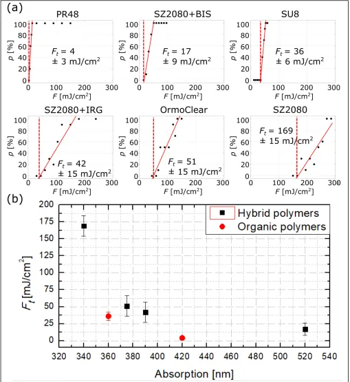
We begin our work by investigating how LIDT values depend on the material. For this purpose, we prepared an array of 3DLL made rectangular bulks. Popular photopolymers are investigated to represent lithographic materials. Namely they are a resin used in typical stereolithographic processes (PR48 from Autodesk), the popular epoxy-based resin SU8, and two hybrid organic-inorganic resins (OrmoClear and SZ2080)?. SZ2080 was used with either of the two following photoinitiators, 4,4’-bis(dimethylamino)benzophenone or 2-benzyl-2-dimethylamino-1-(4 morpholino phenyl)-butanone-1. We will refer to these two photoinitiators using the abbreviations BIS and IRG, respectively. Furthermore, SZ2080 was used as is without a photoinitiator. In the following, these photoinitiators will be referred to by using abbreviations BIS and IRG, respectively. Experimental results of LIDT tests are shown in Fig.2. The highly photoactive PR48 has the lowest LIDT value ofFt= 4±3 mJ/cm2. The second lowest LIDT value belongs to SZ2080 with 1% wt. BIS:Ft= 17±9 mJ/cm2. This result can partly be explained by the relatively long wavelength absorption of BIS that reaches into the visible part of the spectrum (∼520 nm?). The LIDT value for SU8 isF
t = 36±6 mJ/cm2(absorption peak - 360 nm). SZ2080 with 1% wt. IRG and OrmoClear followed withFt= 42±15 mJ/cm2andFt = 51±15 mJ/cm2, respectively. This can be expected as both of these materials are glassy hybrids with absorption in the UV (∼390 nm?,?and∼375 nm?respectively). Finally, SZ2080 with no photoinitiator outperformed all other materials with a LIDT value ofFt = 169±15 mJ/cm2. The absorption spectrum of non-photosensitized SZ2080starts as low as 340 nm?,?). In all of these cases absorption was measured in materials as if they were prepared for fabrication. WithFt plotted as function of absorption we can see a clear correlation. This can be tied with lower order of nonlinearity for tested 1030 nm radiation as absorption peak moves to longer wavelengths. Furthermore, the tendency of hybrids being more resilient that organic polymers at same absorption values is also visible.
Besides absorption, another material characteristic that can influence damage mechanisms is its homogeneity. The linear regression shown in Fig.2is an indication of how homogeneous a fabricated microstructure is. All three worst performing materials have damage dynamic ranges that are relatively narrow, going fromp= 0% top= 100% in less than 50 mJ/cm2. On the contrary, SZ2080 with 1% wt. IRG and OrmoClear have damage dynamic ranges that cover 100 mJ/cm2. Therefore, somewhat inhomogeneous (in terms of LIDT) nature of material at nano-scale can be considered. In such case different nano-constitutes/impurieties of the material have varying LIDT?. Beginning of dynamic damage range starts when constitute having lower LIDT starts being damaged and reaches full 100% when even the more resilient part is being fully affected every time. In this case the source of such inhomogeneity might be the photoinitiators used because, with pure material, dynamic range is again reduced to around 50 mJ/cm2. Interestingly, the definite damage region (p= 100%) for both pure and IRG photosensitized SZ2080 is basically the same, starting at roughly∼200 mJ/cm2. Due to this we can consider photoinitiator to form small conglomerates of lowerFtthat reduce the overall LIDT value.
optimization an easier task .
During woodpile testingaxy= 1.13µm andaz= 0.8µm were kept constant in order to make sure that the structures are transparent for 1030 nm radiation?. Onlydxywas varied thus changing fill ratio and Surface areaSand internal volumeV
of polymerized lines. The values of fill ratio,V andSwere calculated assuming lines to be elipsoids?. Material in this test was pure SZ2080. It is known that the surface defects are one of the primary reasons for optical damage in thin films?. Thus, the goal here was to check if relatively highSand smallV would lead to lower LIDT. The calculation was done assuming the lines in woodpile to have elliptical profile and calculating the internal volume and surface area of such rod. HavingV allows to calculate fill factor (FF), showing how much of volume is taken up by lines in comparison to full same sized bulk. Indeed, with a lot of volume in the structure taken up by air, the thermal diffusion should be minimized. Thus, if LIDT would depend onFF
it would point out to the strong thermal nature of the effect. Thus, LIDT values of woodpiles depend on changes inS/VandFF
are shown in Fig.3(a). No clear dependency can be deduced, thus showing minimal LIDT dependence on woodpilesFFand
S/V ratio with maximal LIDT valueFt= 139.5±15 mJ/cm2ataxy=400 nm.
Due to the woodpile geometry, strength of electrical field E inside of such structure can have some internal peaks. Mathematical modeling was performed in order to visualize it. Standard FDTD modeling procedure described in the literature was used?. Due to peculiarities of mathematical model used onlydxy= 500 nm, 450 nm and 400 nm could be calculated. The modeling shows that changes inaxycan increaseE2value by∼23 time comparing the lowest and the highest value [Fig.3(b)] atdxy= 400 nm anddxy= 500 nm respectively. These peaks are located inside of the woodpile lines, which denotes possible influence to LIDT. Geometries with such a significant increase inE2also proved to have∼27.3% lower LIDT. Therefore relation between woodpile’s photonic properties and its LIDT is evident. Therefore, a care should be taken when using 3D woodpile type structures in high light intensities even if they should be transparent to usable wavelength, as internal distribution ofE2might yield some specific peaks that could consequently damage the structure.
Woodpile testing protocol was repeated with photosensitized woodpiles. The highest acquired LIDT wasFt= 105±7.5 mJ/cm2. As expected, it was lower than LIDT of the most resilient non-photosensitized SZ2080 woodpile by∼24.8%. On the other hand, it exceeded the value acquired with the same photopolymer composition in bulk configuration. This shows that smallerV
of absorbing woodpile outweights potential phonicE2confinement. Nevertheless, this was not noticed in less absorbing pure material. At the same time LIDT difference is a lot smaller between woodpiles that between bulk objects (∼77.4% difference) meaning that geometry is more important than material absorption in the case of woodpiles.
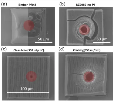
Finally, it is instructive to outline some characteristic structural features of laser-induced damage in some of the investigated materials detail. Fig.4shows SEM images of damage sites in PR48 and pure SZ2080, which correspond to materials that exhibited extreme values of LIDT. As can be seen from Fig.4(a), optical damage in PR48 does not result in formation of crater characteristic for dielectric breakdown countrary to pure SZ2080 (Fig.4(b)). It is likely the result of relatively low crosslinking degree of PR48. In comparison, structural damage in SZ2080 shown in Fig.4(b) exhibits all typical features of Coulomb explosion-driven dielectric breakdown?. Here, a void at the center of the focus, surrounded by a densified region, can be clearly seen. It can be tied to phase transfer from hybrid polymer to ceramics under sever heat?. Hence, we can conclude that low damage threshold in PR48 can be mainly attributed to its soft, possibly partially polymerized state rather than spectral position of the linear absorption edge,λa≈430 nm, in the standard photoinitiator Esstech TPO+ used to photosensitize PR48?. Examples of optical damage in 3D structured pure SZ2080 for two different laserF are shown in Fig.4(c) and (d). At lowerF
(Fig.4(c)), a crater with well-defined edges, and without signs of melting or heat-affected zone is seen at the center of focus. Closer inspection of areas surrounding the crater reveals slight reduction of the woodpile lattice period, which becomes even more evident at highF (Fig.4(d)). It indicates Coulomb explosion as the dominant mechanism of dielectric breakdown in periodic structures in SZ2080.
4 Conclusions
case (Ft= 570±80 mJ/cm2)?and around on order of magnitude smaller than that of fused silica (Ft = 3.21±0.11 J/cm2)?. Funding.NATO (No. SPS-985048) Grant and European Commission’s Seventh Framework Programme Laserlab-Europe IV JRA scheme BIOAPP (No. EC-GA 654148) for the financial support.
Disclosures.The authors declare no conflicts of interest.
References
1. Malinauskas, M.et al.Ultrafast laser processing of materials: from science to industry. Light. Sci. Appl.5, e16133, DOI: 10.1038/lsa.2016.133(2016).
2. Maigyte, L.et al. Flat lensing in the visible frequency range by woodpile photonic crystals. Opt. Lett.38, 2376–2378 (2013).
3. Gissibl, T., Thiele, S., Herkommer, A. & Giessen, H. Two-photon direct laser writing of ultracompact multi-lens objectives.
Nat. Photonics10, 554–560, DOI:10.1038/nphoton.2016.121(2016).
4. Williams, H. E., Freppon, D. J., Kuebler, S. M., Rumpf, R. C. & Melino, M. A. Fabrication of three-dimensional micro-photonic structures on the tip of optical fibers using SU-8. Opt. Express19, 22910–22922, DOI:10.1364/oe.19.022910 (2011).
5. Thiele, S., Arzenbacher, K., Gissibl, T., Giessen, H. & Herkommer, A. M. 3D-printed eagle eye: Compound microlens system for foveated imaging.Sci. Adv.3, e1602655 (2017).
6. Žukauskas, A.et al. Characterization of photopolymers used in laser 3D micro/nanolithography by means of laser-induced damage threshold (LIDT). Opt. Mater. Express4, 1601–1616, DOI:10.1364/ome.4.001601(2014).
7. Jonušauskas, L.et al.Optically clear and resilient free-formµ-optics 3D-printed via ultrafast laser lithography.Materials
10, 12, DOI:10.3390/ma10010012(2017).
8. Jonušauskas, L.et al.Mesoscale laser 3D printing.Opt. Express27, 15205–15221, DOI:10.20944/preprints201810.0384.v1 (2019).
9. ISO21254-2:2011.Test methods for laser-induced damahe threshold-Part 2: Threshold determination(2011).
10. Ovsianikov, A.et al.Ultra-low shrinkage hybrid photosensitive material for two-photon polymerization microfabrication.
Acs Nano2, 2257–2262 (2008).
11. Malinauskas, M., Žukauskas, A., Biˇckauskait˙e, G., Gadonas, R. & Juodkazis, S. Mechanisms of three-dimensional structuring of photo-polymers by tightly focussed femtosecond laser pulses.Opt. Express18, 10209 (2010).
12. Microresist.UV-Curable Hybrid Polymers for Micro Optical Components(2015).
13. Bataviˇciut˙e, G., Grigas, P., Smalakys, L. & Melninkaitis, A. Revision of laser-induced damage threshold evaluation from damage probability data. Rev. Sci. Instrum.84, 045108, DOI:10.1063/1.4801955(2013).
14. Bataviˇci¯ut˙e, G., Šˇciuka, M. & Melninkaitis, A. Direct comparison of defect ensembles extracted from damage probability and raster scan measurements.J. Appl. Phys.118, 105306, DOI:10.1063/1.4929963(2015).
15. Mizeikis, V., Purlys, V., Buividas, R. & Juodkazis, S. Realization of structural color by direct laser write technique in photoresist. J. Laser. Micro. Nanoeng.9, 42–45 (2014).
16. Juodkazis, S., Misawa, H., Hashimoto, T., Gamaly, E. G. & Luther-Davies, B. Laser-induced microexplosion confined in a bulk of silica: Formation of nanovoids. Appl. Phys. Lett.88, 201909, DOI:10.1063/1.2204847(2006).
17. Gaileviˇcius, D.et al.Additive-manufacturing of 3D glass-ceramics down to nanoscale resolution.Nanoscale Horiz.4, 647–651, DOI:10.1039/c8nh00293b(2019).
18. Bennett, J. Measuring UV curing parameters of commercial photopolymers used in additive manufacturing.Addit. Manuf.
18, 203–212, DOI:10.1016/j.addma.2017.10.009(2017).
19. Gallais, L. & Commandré, M. Laser-induced damage thresholds of bulk and coating optical materials at 1030 nm 500 fs.
Figure 3.LIDT dependency onS/V ratio (a)E2(b) andFF(written near each measured point alongsidedxyvalue). (c) -result ofE2modeling inside of woodpiles with the three thickestdxyvalues. Regions enclosed by the red line show the cut of internal features of woodpile. Difference between the highest (atdxy=500 nm) and lowest (atdxy= 400 nm)E2is∼23 times. This follows tendency of increase in LIDT between these two cases by∼27.3% showing that optical resiliency depends on photonic properties of woodpile.