Glonass Software Receiver
Rajkumar L. Biradar
Department of Electronics & Telematics, G.Narayanamma Institute of Tech & Science, Hyderabad, India
ABSTRACT: These days, Global Navigation Satellite System (GNSS) technology plays a critical role in positioning and navigation applications. Use of GNSS is becoming more of a need to the public and military purpose Therefore; much effort is needed to make the civilian part of the system more accurate, reliable and available, especially for safety of life. Global Positioning System (GPS) is the first independent GNSS developed by Department of Defence of USA. The Russian counterpart of GPS is called GLONASS .GLONASS is a radio-based satellite navigation system, developed by the former Soviet Union and now operated by Russian Space which supports 8 satellites in each of its 3 orbits, with a total of 24 satellites covering globally. The primary goal of the software receiver is to minimize the hardware used in a receiver.
KEYWORDS: Global navigation satellite system, Global positioning system, receiver
I. INTRODUCTION TO GNSS RECEIVER
Global Navigation Satellite System (GLONASS) is a satellite-based navigation system that has been used widely both in civilian and military for positioning, navigation, timing and other position related applications. The hardware-based GLONASS (or) GPS receivers provide the least user flexibility. Thus, it is necessary to have Software-based GNSS receivers for easy and quick implementation, simulation and analysis of algorithms. Software-based GNSS receiver processes the GLONASS or GPS signal at the radio frequency or intermediate frequency depending on the hardware configuration of the receiver. In this development of the acquisition and tracking processes of the software receiver, the front-end part converts the radio frequency signal from the antenna to an intermediate frequency in GLONASS receiver board. An analog-to-digital (A/D) converter then digitizes the output signal from the RF front-end. The data is then processed using MATLAB programs to achieve acquisition and tracking of the GLONASS satellite signals. The software GLONASS receiver can perform acquisition and tracking using different parameters and threshold values. This flexibility of operation allows weaker signals to be tracked and processed. In a conventional GNSS receiver, the acquisition and tracking of the signals are all processed by the hardware. However, in a software GNSS receiver, the signal is digitized using an analog-to-digital converter (ADC). The digitized input signal is then processed using the software receiver. The acquisition process searches for the presence of a signal from a particular satellite, and the tracking program finds the phase transition of the navigation data from that satellite. Ephemeris data and pseudo ranges can be recovered from the navigation data bits. Finally the user position can be calculated from the ephemeris obtained.
II. LITERATURE SURVEY
Earth orbit satellites and five geostationary satellites. A 12-satellite regional version is expected to be completed by 2012. The European Union and European Space Agency agreed in March 2002 to introduce own alternative to GPS, called the Galileo positioning system [3]. At an estimated cost of EUR 3.0 billion, the system of 30 MEO satellites was originally scheduled to be operational in 2010. The estimated year to become operational is 2014. The first experimental satellite was launched on 28 December 2005. Galileo is expected to be compatible with the modernized GPS system. The receivers will be able to combine the signals from both Galileo and GPS satellites to greatly increase the accuracy. Galileo is now not expected to be in full service until 2020 at the earliest and at a substantially higher cost.
The Indian Regional Navigational Satellite System (IRNSS) is an autonomous regional satellite navigation system being developed by Indian Space Research Organization (ISRO) which would be under the total control of government of India [4]. The government approved the project in May 2006, with the intention of the system to be completed and implemented by 2014. It will consist of a constellation of 7 navigational satellites. All the 7 satellites will be placed in the Geostationary orbit (GEO) to have a larger signal footprint and lower number of satellites to map the region. It is intended to provide an all-weather absolute position accuracy of better than 7.6 meters throughout India and within a region extending approximately 1,500 km around it. A goal of complete Indian control has been stated, with the space segment, ground segment and user receivers all being built in India.
III. BASIC GNSS RECEIVER ARCHITECTURE
A basic software-based GNSS receiver is composed of two main parts. The first part covers the hardware and can be divided in two functional blocks: RF section and IF section. The RF section consists of analog hardware modules, responsible for RF to IF conversion, while the IF section is composed of digital hardware modules. The second part is the baseband software processing, which performs acquisition and tracking of the received signals, as well as the necessary algorithms used for the computations of the receiver PVT.
Basically GNSS receivers consist four blocks: antenna, RF front end, local oscillator, signal processing block. The antenna is first element of receiver architecture. The transmitted signal from satellites is Right Hand Circularly Polarized (RHCP), so the antenna must be designed to receive RHCP signals. The operation of all radio-navigation systems is based on the assumption that the propagation mechanism of radio waves is well known and that the propagation speed of radio waves is usually very close to the speed of light in free space.
Finally, all of the measurements on radio waves, like direction finding, time-delay measurements, phase measurements or Doppler-shift measurements can be performed on the user side. The radio signals collected by an Omni directional receiving antenna are weak. Due to the GNSS signal’s low power upon reception, there is usually a set of filtering and noise amplification stages after the antenna for amplifying the weak signal. This is achieved by the means of low-noise amplifier (LNA).
Antenna
Analog IF
L.O
Figure 1 Basic software GNSS receiver
Reference
Oscillator
Frequency
Synthesize
r
Preamplifier
Down
Converter
Filter
AGC
A/D Converter
Navigation
Processing
Tracking
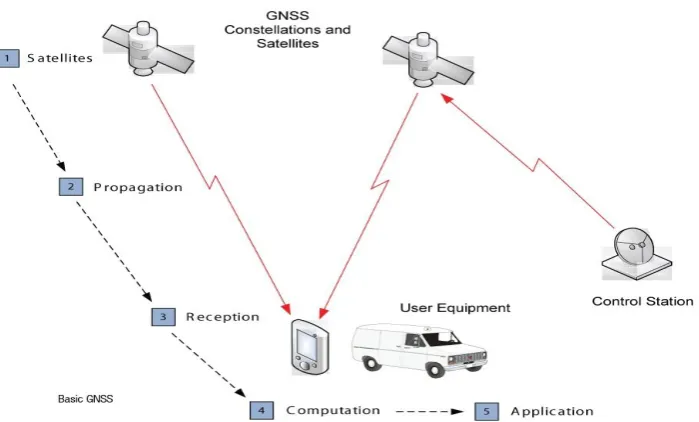
Figure 2 Signal transmission and reception
A generic RF front end consists of amplifiers, filters, and mixers. A typical RF front end is shown in figure 3. After receiving signal from antenna is then forwarded and processed in the RF front-end. In the RF front-end of software based GLONASS receiver first component is preamplifier after antenna; it is often used very close to antenna. The antenna may capable receiving multiple frequency bands. After amplification of the signal coming from the preamplifier, is sent to down conversion part to convert input signal from RF to a low IF. This down-conversion is accomplished by mixing the input RF signal with the local oscillator (LO) generated signal, which must be carefully chosen to avoid harmonics and image frequencies near IF, using one or two mixers followed by an appropriate band pass filtering. The signal having Doppler and the PRN codes are preserved after the mixing process, only the carrier frequency is lowered. The resulting analog IF signal is then converted to a digital IF signal through the analog-to-digital converter (ADC). Here ADC sampling frequency, Fs, should be carefully chosen. The requirements to prevent
signal aliasing define a minimum sampling frequency, called Nyquist frequency, as Fs = 2B, where B represents the analog (low pass) signal bandwidth.
The IF digital signal is then transmitted to a post processing unit, which will handle all the baseband processing and necessary computations to achieve the receivers PVT. There are various GNSS receivers specifically designed for
various range of applications. It is very difficult to define a typical type of conventional hardware GNSS receiver. However, a characterization of a generic GLONASS receiver can still be made based on the receiver design requirements. A generic GLONASS receiver functional block diagram is shown in Figure 1. A GLONASS receiver can be broken down into various components. First, the antenna, possibly followed by a pre-amp, receives the RF GLONASS signals.
3.1 RF Front End
In satellite communication, high carrier frequencies are necessary to propagate signals from space through the atmosphere. However, these high frequencies are not easy to filter and demodulate at Receiver. Therefore, down-conversion, by mixing the incoming signal and noise with a Local Oscillator (LO), is applied to reduce the received carrier frequency to a more manageable value. Usually, the receiver RF front-end is second part in the receiver architecture after the antenna and LNA. Once the signal has been down-converted and filtered, it is ready to be sampled. Sampling performs by analog-to-digital conversion of the GLONASS signal. The analog voltage that results from the incident GLONASS signal and thermal noise remains much too weak and at too high a frequency for most analog-to-digital converters (ADCs) to operate.
3.2 Down Conversion
So far, the modeled GLONASS signal is still at radio frequency. After the signal propagation enter in to the front end and is down-converted to the IF frequency using Mixer. Down-conversion in the front-end is the process of taking the RF signal down to some lower frequency (either an intermediate frequency, or directly to baseband) where it is easier to process.
IV. RF FRONT END COMPONENTS
The process begins with the GNSS signal, propagating through space, which is incident on a user’s GNSS antenna. This, in turn, induces a voltage within the element. That voltage is extremely weak, corresponding to a guaranteed signal power of −161 dBW in the case of the Global Navigation Satellite System (GLONASS) [see ICD-GLONASS-2002] and has a carrier frequency of L1 (1598MHz – 1605.5MHz) sub band.
4.1 Low Noise Amplifier
Low-noise amplifier (LNA) is an electronic amplifier used to amplify possibly very weak signals (for example, captured by any active or passive antenna). It is also called as Preamplifier. The primary purpose of the preamplifier is to amplify the signal at the output of the antenna for further processing. However, it is vital that this amplifier has a very low noise figure, hence the amplifier is usually referred to as a Low Noise Amplifier (LNA).
4.2 Mixer
These both can be done by Mixer and RF signal shifted by FC + FL and FC - FL. At the mixer output, a sinusoidal signal
with an intermediate frequency (IF) appears. In fact, this Intermediate frequency is the difference between incoming signal frequency and the locally generated signal frequency (IF = FRF +FLO).
4.3 Filter
A filter is a frequency selective device that allows only certain frequencies to pass and attenuates others. Here filter is a band pass filter, as opposed to a low pass or high pass filter, and its purpose is to provide additional frequency selectivity. The second filter parameter is the bandwidth. Again, since no filter is ideal, typically a 3 dB bandwidth is specified. This indicates at which frequency(s) the attenuation will be 3 dB (or 50% of the signal power).
4.4 Amplifier
Amplification is the process that increases the signal magnitude. Thus, an amplifier is a component that does just that. Unlike most filters, an amplifier is an active component and requires power to accomplish its function. Note that the ideal amplifier would only increase the amplitude of the signal.
4.5 Intermediate Frequency
In communications and electronic engineering, an intermediate frequency (IF) is a frequency to which a carrier frequency is shifted as an intermediate step in transmission or reception. The intermediate frequency is created by mixing the carrier signal with a local oscillator generated signal in a process called heterodyning, resulting in a signal at the difference or beat frequency.
4.6 Local Oscillator
oscillator frequency for the L1 GNSS signal. Thus, a phase lock loop (PLL) is combined with the crystal to achieve the desired higher frequency of the local oscillator. In addition, it is common practice that the local oscillator be divided down to serve as the sampling clock.
4.7 Analog to Digital Converter (ADC)
The final component in the RF front-end hardware part is the analog-to-digital converter. This component is responsible for the conversion of the analog signal to digital samples. The IF signal is then sampled and digitize through the ADC. The resulting samples are processed by signal processor.
5 C/A Code Generations for Different Sampling Frequencies
The generated C/A code shown in figure 6, C/A code consist within 1ms, which consist one set of C/A code at sampling frequency of 0.511MHz shown in below via by expressing C/A code vs. Time
1
𝑠𝑎𝑚𝑝𝑙𝑖𝑛𝑔 𝑓𝑟𝑒𝑞𝑢𝑒𝑛𝑐𝑦 × (0: code length -1)
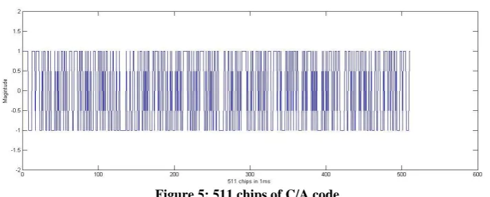
GLONASS satellites generate C/A code having 511 chips/ms with a clock rate of 511kcps, this code repeats every 1ms, and each group of 511 chips represents one C/A code and is same for every satellite. In our case GLONASS satellite generated signal is down converted into Intermediate frequency which is sampled at a rate of 16MHz sampling frequency through A/D converter, resulting signal is required to process for acquisition and tracking a satellite generated signal. But here we are observing 511 chips of C/A code for different sampling frequencies and its spectrum of C/A code. To the above C/A code when we have applied FFT or DFT, it will convert C/A code from time domain to frequency domain, because in frequency domain we can easily analyze the spectrum of C/A code which is shown in below figure. Here the sampling frequency is 0.511MHz.
Sampling frequency
511 × (0: code length -1) = 0.511 MHz
511 × (0:510)
When C/A code sampled at 0.511MHz, it generates 511kcps means 511chips/ms so each sample takes 1 kHz frequency resolution.
Sampling frequency
Cacode length × (0: Cacode length -1) = 0.511 MHz
511 × (0:511-1)
Sampling frequency can be defined as a discrete time signal generated from a continuous signal or converting a continuous time signal in to discrete time signal.
Example: x (n) = 4 samples/sec (1010)
After increasing the sampling frequency 2 × x (n) = 8 samples/sec (11001100).
Figure 6: C/A code vs. Time
Therefore the signal properties have not changed but sampling frequency is increased due to that one chip is replace with 2 samples and also we get the accuracy. Similarly same concept here we have applied to 0.511MHz of C/A code. When the C/A code is sampled at 1.022MHz, maximum frequency component will be having at 0.511MHz and the spectrum of 1.022MHz sampled c/a code is shown in below figure
Fs ≥ 2Fmax = 1.022MHz ≥ 2×0.511MHz
Figure 7: FFT of C/A code at sampling
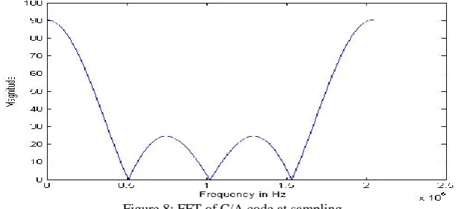
Similarly if C/A code is sampled at 2.044MHz means C/A code sampled to 4 times of its code frequency so here each chip will be replaced with 4 samples and the spectrum of 2.044MHz sampled C/A code is shown in below figure
Above graph explains the minimum frequency is 2.044MHz and the maximum frequency is 0.511MHz.In GLONASS receiver, sampling of c/a code plays a very important role to digitizing the C/A code.
Sampling frequency (Fs) = 32 × 0.511MHz = 16MHz, Fmax = Fs
32 = 0.511MHz.
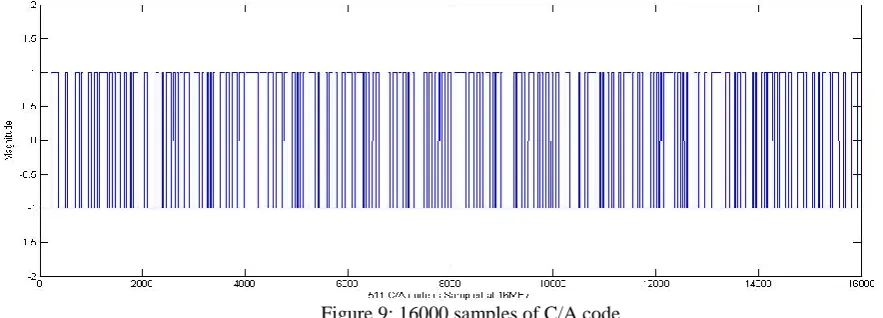
When 0.511MHz C/A code is sampled to16MHz sampling frequency so each chip will be sampled or digitized by 31 samples and the frequency resolution of each sample takes 1 kHz. Therefore 511 chips will be sampled to16000 samples/ms. the 16MHz sampled C/A code is shown in below fig.
Figure 9: 16000 samples of C/A code
After sampling C/A code of 0.511MHz to 16MHz, Sampling time (Ts) = 6.25×10
-8
sec Chip duration (Tc) = 1.95×10⁻⁶sec
To the above C/A code, when we applied DFT or FFTto 16MHz sampled c/a code, the spectrum of c/a code shown in below fig here. The transmitted c/a code is having main lobe and several side lobes because of sampling frequency is very high compare to its code frequency .
V. CONCLUSION
This paper introduces about GLONASS satellite signal structure and Coarse Acquisition code, frequency allocation of channels and auto correlation properties of C/A code of GLONASS software receiver. It explains properties of C/A code at different sampling frequency.
REFERENCES
1. Yuying Zheng and Xi’an. “A Software-based Frequency Domain Parallel Acquisition Algorithm for GPS Signal” in 2010 IEEE, China.
2. A. J. Van Dierendonck, B. W. Parkinson and J. J. Spilker, Jr, Eds.Washington, “GPS Receivers, in Global Positioning System”:Theory and Application, DC: Amer. Inst.
3. Bao, J. and Tsui, Y. . Fundamentals of Global Positioning System Receivers: a Software Approach.John Wiley & Sons, Inc., pp. 133.
4. Rao, K.N.Suryanarayana ”Indian Regional Navigation Satellite System(IRNSS),” Second Meeting of the United Nations International
Committee on Global Navigation Satellite System(ICG),Banglore,India,September 4-7,2007.
5. Bartenev, V., Kosenko, V. E., Zvonar, V. D. and Chebotaryov, V. E. (2005). Space vehicle GLONASS-M.Peculiarities of goal designing. 10th International Conference on System Analysis, Controlling and Navigation, Eupatoria, 3–10 July.