ABSTRACT
NAJAFI, MESBAH. Improving Mechanical Properties of Nylon and Polyester Yarns by Horizontal Isothermal Bath Method. (Under the direction of Dr. Richard Kotek).
Several techniques and treatments have been used for the production of high tenacity polyamide and polyester yarns. The inherent problems of low productivity, high production cost, and high energy consumption, complexity of chemical reaction, mass transfer and waste recovery systems make most of them inappropriate for industrial application. Horizontal isothermal bath (HIB) is an alternative eco-friendly simple treatment that can be utilized during melt spinning process for production of high performance fibers. The method contributes to high tensile properties through developing unique fiber morphology, transformable into highly oriented, order crystalline structures under mild drawing and heating. The drawing can be performed on HIB yarn during (i.e. continuous system) or after (i.e. batch system) the spinning process.
In the second study, the effect of HIB and post-drawing on the tensile properties of poly trimethylene terephthalate (PTT) yarns was examined. PTT is an interesting polyester for textile products, as it has combined physical properties of nylons (PA-6 and PA-66) and other aromatic polyesters (PET and PBT). PTT filament is the most promising candidate for replacement of PET fiber, due to the properties such as lower melting point, easier processing and dyeing, and higher flexibility. The results showed that the bath treatment increased considerably the fiber orientation and crystallinity up to 0.066 by 66% and 47.94% by 100%, respectively. Drawing the HIB fibers with a low draw ratio of 1.11 increased the tensile strength up to 4.76 g/d and reduced the tensile strain down to 51.76%. Such the strength is greater than the maximum value (3.3 g/d) reported before. The obtained results can widen application of PTT fibers in technical woven/nonwoven products.
Improving Mechanical Properties of Nylon and Polyester Yarns by Horizontal Isothermal Bath Method
by Mesbah Najafi
A dissertation submitted to the Graduate Faculty of North Carolina State University
in partial fulfillment of the requirements for the degree of
Doctor of Philosophy
Fiber and Polymer Science
Raleigh, North Carolina 2017
APPROVED BY:
BIOGRAPHY
ACKNOWLEDGMENTS
First, I would like to express my sincere gratitude to my advisor Dr. Richard Kotek for the continuous support of my Ph.D. study and related research, for his patience, motivation, and immense knowledge. His guidance helped me in all the time of research and writing of this dissertation.
This gratitude is also extended to my committee members Drs. Sam Hudson, Xiangwu Zhang, Saad Khan, and Jan Genzer for serving my graduate committee and providing useful suggestions required to complete this study.
My Ph.D. research could not have been completed without help of technical staffs. I acknowledge Birgit Anderson, Teresa White, and Judy Elson in College of Textiles, and Chuck Mooney and Ching-Chang Chung in Analytical Instrumentation Facility for their assistance. I greatly appreciate Trützschler and Honeywell Companies for funding this study. I also thank Dr. Lassad Nasri and Dr. Terry Chern for providing useful commends for my projects.
I would also like to thank my family for their support and encouragement throughout my education.
TABLE OF CONTENTS
LIST OF TABLES ... vii
LIST OF FIGURES ... ix
Chapter 1 : Literature review ... 1
1-1 Introduction ... 1
1-2 Fiber formation methods ... 3
1-2-1 Melt spinning... 3
1-2-2 Two-step process ... 12
1-2-3 High speed spinning ... 13
1-2-4 Direct-spin draw process ... 17
1-2-5 Zone drawing-zone annealing ... 18
1-2-6 Solid-state polymerization ... 21
1-2-7 Solution spinning... 23
1-2-8 Spinning with plasticizers ... 32
1-2-9 SymTTec ... 44
1-2-10 Liquid isothermal bath (LIB) ... 52
1-2-11-Horizontal Isothermal Bath (HIB) ... 67
1-3 Structure of high-performance nylon fibers ... 71
1-3-1 Amorphous structure ... 73
1-3-2 Crystal structure ... 74
1-3-3 Characterization ... 79
1-4 Nylon-6 Fiber properties ... 82
1-4-1 Tensile properties ... 82
1-4-2 Thermal properties ... 86
1-4-3 Chemical properties... 88
1-5 Applications of high-performance nylon fibers... 89
1-6 References ... 92
Chapter 2 : High Performance Filaments by Melt Spinning Low Viscosity Nylon 6 Using Horizontal Isothermal Bath Process ... 101
2-1 Abstract ... 101
2-2 Introduction ... 102
2-3-1 Materials and sample preparation ... 106
2-3-2 Measurements and characterization ... 107
2-4 Result and discussions ... 111
2-4-1 Tensile properties ... 111
2-4-2 Fiber morphology ... 113
2-4-3 Crystal and amorphous structures ... 115
2-4-4 Molecular orientation ... 120
2-5 Conclusion ... 122
2-6 References ... 123
Chapter 3 : Improving Mechanical properties of Poly (trimethylene terephthalate) Fibers by Sustainable Horizontal Isothermal Bath Process ... 127
3-1 Abstract ... 127
3-2 Introduction ... 128
3-3 Experimental approach ... 131
3-3-1 Materials and sample preparation ... 131
3-3-2 Measurements and characteristics ... 132
3-4 Results and discussions ... 133
3-4-1 Tensile properties ... 133
3-4-2 Thermal properties ... 139
3-4-3 Molecular orientation ... 142
3-4-4 Crystalline structure ... 143
3-4-5 Fiber morphology ... 147
3-5 Conclusion ... 149
3-6 References ... 150
Chapter 4 : Improving Mechanical Properties of Polyethylene Terephthalate Yarns by Continuous HIB Process ... 154
4-1 Introduction ... 154
4-2 Materials ... 157
4-3 Experimental techniques ... 157
4-4-3 HIB process with other liquids ... 175
4-4-4 Thermal properties ... 180
4-4-5 Molecular orientation ... 183
4-4-6 Crystalline structure ... 184
4-4-6 Fiber morphology ... 185
4-5 Conclusion ... 187
LIST OF TABLES
Table 1-1 Comparison of production cost in three fiber formation methods [12] ... 18
Table 1-2 Various solution spinning methods used for nylon-6 [34] ... 28
Table 1-3 Tensile properties and orientation factor of crystalline region of regenerated nylon 6,6 continuous fibers initially spun at 1 m/min following hot drawing. Temperature of spinning: 60 -70 °C, dope concentration of nylon 6,6 in complex: 4-5 wt%. [39]. ... 44
Table 1-4 Effect of liquid temperature on structural and mechanical properties of LIB spun (PET) fibers [18] ... 59
Table 1-5 Effect of bath position on structural and mechanical properties of LIB spun (PET) fibers [18] ... 60
Table 1-6 Properties of various PET fiber samples [71]... 62
Table 1-7 Mechanical and structural properties of PEN fibers spun at 4000 m/min [72] ... 66
Table 1-8 Comparison of tensile properties of nylon fibers spun with different techniques [99] ... 67
Table 1-9 Structural characteristics of undrawn and drawn PP fibers with and without ECOB [66] ... 70
Table 1-10 Comparison of some physical and structural characteristics of α and γ forms for nylon-6 fiber... 78
Table 1-11 Thermal and moisture properties of nylon-6 and 66 fibers ... 88
Table 2-1 Fiber denier and tensile testing results of various nylon-6 multifilament yarns .. 112
Table 2-2 Crystalline and amorphous parameters for undrawn and drawn (DR=1.38) control and hIB nylon-6 yarns ... 119
Table 3-1 Tensile properties of as-spun control (no HIB) and HIB PTT fibers. ... 136
Table 3-2 Tensile properties of undrawn and drawn control and HIB PTT fibers ... 138
Table 3-3 Thermal properties of undrawn and drawn control an HIB PTT yarns ... 141
Table 3-4 Molecular orientation of undrawn and drawn control and HIB PTT fibers ... 143
Table 3-5 Tensile and structural properties of undrawn and drawn HIB (DR=1.11) and control PTT yarns ... 146
Table 4-1 Tensile properties of undrawn control and HIB high Mw (IV=1.05 dL/g) PET yarn in batch system ... 160
Table 4-2 Tensile properties of undrawn and drawn (DR=1.27) control and HIB high Mw (IV=1.05 dL/g) PET yarns ... 160
Table 4-3 Tensile properties of as-spun high Mw (IV=1.05 dL/g) PET yarns ... 161
Table 4-4 Tensile properties of HIB and control low Mw (IV=0.66 dL/g) PET Invista yarns ... 163
Table 4-5 Spinning conditions for production of control high Mw PET (IV=1.05 dL/g) yarn ... 164
LIST OF FIGURES
Figure 1-1 Performance vs. Cost for various technical fibers [10] ... 3 Figure 1-2 Scheme of melt spinning and drawing of nylon yarn [16]. ... 7 Figure 1-3 Cohesive fracture of a steady-state jet in melt spinning [14]. When the threadline stress (Pxx) exceeds its tensile strength, the fluid breakage happens. ... 8 Figure 1-4 Break-up of a polymer jet in melt spinning due to capillary wave [14]. R(x) represents the radius of undistorted jet, δ(x) is the profile changes of the capillary wave. ... 9 Figure 1-5 The individual contributions to spinline tension at different distances from
spinneret [14]. ... 10 Figure 1-6 The velocity profile in (a) shear flow in a capillary, and (b) elongational flow in a spinline [13]. ... 12 Figure 1-7 Effect of take-up speed on the residual draw ratio of nylon fiber. LOY, MOY, POY, HOY, and FOY stand for low, medium, partially, highly, and fully oriented yarn, respectively [16]... 14 Figure 1-8 Influence of take-up speed on the tenacity (—), initial modulus (----), and
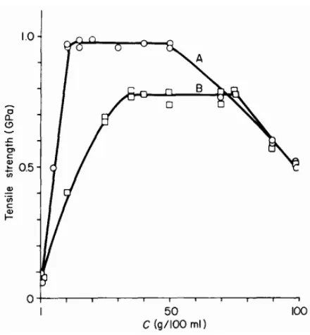
elongation (…..) of PA-6 fiber [16] ... 15 Figure 1-9 Schemes of panumatic cooling (left) and cross-flow quanch (right) systems [51] 16 Figure 1-10 Scheme of the heater below the spinneret in melt spinning: 1) spin pack, 2) annular heating strip, 3) radiation heater [51] ... 17 Figure 1-11 Spin-draw process for nylon-6 tire cord yarn [12] ... 18 Figure 1-12 Scheme of apparatus for zone-annealing method [22]. ... 19 Figure 1-13 Representation of apparatus used for the vibrating hot-drawing method [22] .... 20 Figure 1-14 A typical dry-spinning process... 25 Figure 1-15 Tensile strength vs. spinning solution concentration for nylon-6 filaments: A, Mw= 2.6 ˣ106, B, 9.4ˣ104. filaments were stretched at optimum draw temperature to
Figure 1-25 Tensile properties of SwissTex and commercial nylon-6 yarns. HV and NV are
related to high and normal PA-6 viscosities, respectively [84] ... 46
Figure 1-26 Extruder with gravimetric dosing system in SymTTec [85]. ... 48
Figure 1-27 New designed spin packs for high polymer melt quality in SymTTec (Up). Individual annealers for excellent thermal treatments of filaments bundles (Down) [84] ... 49
Figure 1-28 Air turbulence free quench system in SymTTec. The intefloor tube is no longer a passive system, as it can have considerable effect on the yarn cooling ... 50
Figure 1-29 Draw rolls with 5 duos [84] ... 51
Figure 1-30 RIEVAP dual sell draw rolls (left), and high speed winder (right) used in SymTTech [84] ... 52
Figure 1-31 Heat pipe mechanism (left), and exceptional uniform temperature profile over the heated length (right) in the RIEVAP draw roll [86] ... 52
Figure 1-32 Liquid isothermal bath process: 1) spinneret, 2) extruder, 3) hot short sleeve, 4) liquid bath, 5) sliding valve, 6) closed liquid catching device, 7 & 8) guides, 9) godet, 10) yarn package. ... 54
Figure 1-33 Effects of take-up speed on tensile properties (left) and density and birefringence (right) of the LIB spun fibers and as-spun fibers without LIB [18] ... 57
Figure 1-34 Effects of the liquid depth on birefringence, density, and orientation factors of the LIB spun (PET) fibers [18]. ... 57
Figure 1-35 Parallel polarization interference patterns of the PET samples F from Table 1.5, under different LIB conditions: (a) Position 0 (17 cm); (b) Position 1 (22 cm); (c) Position 2 (37 cm); (d) Position 3 (36 cm). Take-up speed and liquid temperature of all samples are 4000 m/min and 140°C, respectively. [18]. ... 61
Figure 1-36 Wide angle X-ray diffraction profiles of PET fiber samples A-F from Table 1.6 [71] ... 64
Figure 1-37 Scheme of horizontal isothermal bath (HIB) method [73] ... 68
Figure 1-38 Morphological model for nylon-6 fiber: 1-fibril, 2-crystallites, 3- partially extended molecules in the inter-fibrillar regions, 4- tie molecules in the interlamellar amorphous region, 5- free chain ends, 6-voids and interfibrillar amorphous region (Adapted from Murthy et al. [88]) ... 73
Figure 1-39 Schematic of nylon-6 fiber structure at various scales [91] ... 74
Figure 1-40 Structures of α and γ crystals for nylon-6 and nylon-66 [3] ... 77
Figure 1-41 Deconvolution of X-ray intensity versus Bragg angle (I-2θ) plot into crystalline, oriented amorphous (OA) and unoriented amorphous (UA) components for nylon-6 fiber [73] ... 81
Figure 1-42 Crystal orientation with respect to the fiber axis [7] ... 81
Figure 1-43 Schematic of stress-strain curve [101] ... 84
Figure 1-44 Elongation vs. crystallinity for PA-6 and 66 fibers [8] ... 84
Figure 1-45 Variations of crystalline (alpha, gamma), unoriented amorphous (Unor. Am.), and oriented amorphous (Or. Am.) components upon drawing for nylon-6 fiber [100] ... 85
Figure 1-47 Effect of annealing temperature on the crystal size of α (●) and γ (○) (left), and
crystalline fraction (crystallinity) for PA-6 fiber (right) [105] ... 86
Figure 1-48 Effect of the frequency of amide groups on the melting point of polyamides. The number on the curves indicate the specific polyamide [2]. ... 87
Figure 1-49 Changes of the Tg with crystallinity (left) and amorphous isotropy (F(oa)) (right) for nylon-6 fiber ... 88
Figure 1-50 World polyamide production [106] ... 91
Figure 1-51 Word fiber production of various polymers 1980-2025 [106] ... 91
Figure 2-1 Schematic of horizontal isothermal bath (hIB) method ... 105
Figure 2-2 Illustration of outside, transit and inside zones for fiber drawing... 113
Figure 2-3 Cross sectional view of the drawn control and hIB nylon-6 filaments (DR=1.38) at two different magnifications (up: 2500×, 10 µm scale; down: 10000×, 2 µm scale): drawn control (a, d), drawn hIB at transit zone (b, e), drawn hIB at inside zone (c, f). ... 115
Figure 2-4 Equatorial scans of various nylon-6 multifilament yarns ... 118
Figure 2-5 Deconvolution of equatorial I-2θ plot into crystalline and amorphous components for various nylon-6 yarns: a) undrawn control, b) drawn control (DR=1.38), c) undrawn hIB, d) drawn hIB (DR=1.38). The blue dotted and green solid lines are related to experimental and calculated curves respectively ... 119
Figure 3-1 Chemical structure of PTT [3] ... 128
Figure 3-2 Comparison of crystallization half-times (t1/2) for PET, PTT, and PBT at the same under-cooling degrees from the melts (Left) [11]. Polymer structures of three polyesters: PET, PTT and PBT, the methylene groups are shown as black filled circles (Right) [4]. ... 129
Figure 3-3 Scheme of horizontal isothermal bath (HIB) method [25] ... 131
Figure 3-4 Modified tensile tester equipped with a heating tower for drawing PTT yarns. The length of the tower is 68 cm. ... 137
Figure 3-5 Stress-strain curve of undrawn and drawn HIB and control PTT fibers ... 139
Figure 3-6 DSC curves of undrawn HIB and control PTT yarns at 1000 and 2000 m/min take-up speeds ... 141
Figure 3-7 2D WAXS photographs of undrawn control (a), undrawn HIB (b), (c) drawn control (DR=1.40), and (d) drawn PTT (DR=1.11) yarns ... 144
Figure 3-8 Equatorial scans of undrawn and drawn control and HIB PTT yarns ... 146
Figure 3-9 Equatorial scans of as-spun PTT fibers at different spinning speeds [9] ... 147
Figure 3-10 Cross sectional view of Undrawn control (top) and undrawn HIB (down) at three magnifications (left: 1,000х, 50 μm scale; middle: 5,000х; 10 μm scale, right: 10,000 x 5 μm scale). ... 148
Figure 3-11 Microscopy images of drawn untreated (DC-2000) and treated (DH4-2000) PTT filaments. ... 149
Figure 4-4 Thermograms of various PET yarns in continuous HIB process; a) undrawn control (MN67-090716); b) drawn control with DR of 5.2. (MN66-112716); and c) drawn HIB with DR of 1.3 (MN44-092616) ... 182 Figure 4-5 Equatorial X-ray scans of undrawn control (MN67-090916), drawn control with DR of 5.2 (MN66-112716), and drawn HIB with DR of 1.3 (MN44-062916) ... 184 Figure 4-6 Cross sectional view of undrawn control (a, b), undrawn HIB (c, d), drawn control at DR=5.2 (e, f), and drawn HIB at DR=1.3 (g,h) PET filaments at two different
Chapter 1
: Literature review
1-1 Introduction
Nylon or polyamide (PA) is known as the second most important man-made polymer for textiles after polyester [1]. It was first developed by a brilliant chemist, Wallace H. Carothers in 1930s at DuPont research facilities [2]. Properties such as stiffness, toughness, lubricity, and resistance to temperature, fatigue, and abrasion make nylons one of the most versatile thermoplastics in use today [3]. The most important application of nylons is as fibers, which cover a wide range of textile, apparel, and industrial products [4]. Nylon filaments for technical requirements or functions are known as high performance (technical) fibers. Based on application, technical nylon fibers can be classified into several categories such as high tenacity-high modulus fibers, flame retardant fibers, chemical resistance fibers, and conductive fibers [5]. Among them, the high tenacity fibers are in particular interest as they have high tensile performance as well as good chemical, and thermal stability [6].
diamines and dicarboxylic acids, and ring-opening polymerization of lactams. PA-6 and 66 are the two principal nylons used for technical fibers due to combination of tensile properties, process flexibility, and abrasion resistance. Nylon-6 is synthesized through ring-opening polymerization of caprolactam while nylon-66 is synthesized by polycondensation from adipic acid and hexamethylene diamine [7, 8]. High tenacity, high elasticity, good adhesion to rubber, and resistance to abrasion and chemicals make these nylons filaments attractive for various technical applications such as tire cords, surgical sutures, friction bearing, cloths, threads, ropes and nets [7, 9].
Nylon-n : ‒[‒(NH‒CO)‒(‒CH2)n-1‒]‒
Nylon-mn : ‒[‒(NH‒CO)‒(‒CH2)n-2‒(CO‒NH)‒(CH2)m‒]‒
Chemical structure of nylon-n and nylon-mn [3].
axis and the chain ends defects need to be reduced [11]. This can be achieved through modifying fiber formation processes and thermo-mechanical treatments. In this chapter, we will elaborate recent advances in spinning methods and treatments for production of high tenacity nylon yarns.
Figure 1-1 Performance vs. Cost for various technical fibers [10]
1-2 Fiber formation methods
1-2-1 Melt spinning
Melt spinning was used first in the early’s 1930 by W.H. Carothers and coworkers at DuPont Company for fiber formation of polyamides. They synthesized nylon-6,6 from hexamethylene diamine and adipic acid in 1935, and produced successfully commercial nylon filaments and yarns in 1939. The success of nylon led to commercial application of other synthetic fibers such as polyester, and polyolefin fibers [7], [13]. The major development in melt spinning happened in 1970s when high speed spinning was introduced. With such technological development, production of synthetic fibers at take up speed of 3000 m/min and above became possible. Nevertheless, such high speed technology was not used promptly in textile industry and fibers were still produced at relatively low take up speed because of the problem of heat removal. The chronological development in melt spinning process is as follows [12], [13]:
• Conventional melt spinning (e.g. two-step process)
o In the 1st step: melt spinning of the polymer at 1000-1500 m/min for production of yarns with low orientation and crystallinity
o In the 2nd step: drawing and annealing of the yarns at 400-1000 m/min (Draw ratio: 3-4) to improve the mechanical properties of the as-spun yarn.
• Direct spin-draw process (e.g. one-step process)
o Spinning and drawing operation are carried out in one continuous process. o The ultimate take-up speed can be as high as 6000 m/min but the spinning
speed is less than 4000 m/min. • High speed spinning
o Further drawing process (DR=2) may be applied sequentially or simultaneously on the yarn.
• Super high speed spinning
o Spinning at 4,000 to over 6,000 m/min.
o Further slight drawing may be applied on the as-spun yarn.
1-2-1-1 Advantages of Melt spinning
complexity of those fiber formation methods. Finally, in melt spinning, the solidification process can be easily done by exposing the filaments to a cooling air after extrusion. But, in solution spinning, the solidification is done by an outlet gas or a coagulation bath and hence it is a challenging process [13]–[15].
1-2-1-2 Melt spinning process
Melt spinning process comprises several steps including polymer melting, transporting, spinning, quenching, finish application and wind up (Figure 1.2). This follows by other processes such as comingling (interlacing), fiber drawing, yarn texturizing, and package formation. The polymer melt can be obtained either from melting the polymer chips through an extruder or directly from the polymerization vessel. In the case of polymer chips, the moisture content of the polymer needs to be lowered to a consistent moisture level (about 0.12%), as moisture can result in polymer degradation and poor fiber quality [7]. The chips pass through several components during melt spinning to become multifilament yarns (Figure 1.2). When the chips are poured inside the hopper, they move toward an extruder. The extruder comprises of a screw rotated by a motor and a cylindrical barrel heated along its length. The barrel has several heating zones and their temperatures are set usually 30ºC higher than polymer melting point (Tm). Inside the barrel, the polymer chips are melted by the heat and mixed by the mechanical shearing of the rotating screw [13].
1-2-3-1 Filaments breakage in melt spinning
In order to understand fiber formation in melt spinning, the physical mechanism of fiber breakage needs to be perceived well. Filament breakage in melt spinning is influenced by at least two different mechanisms: cohesive failure and capillary wave breakage. In cohesive failure, fiber is broken when the threadline stress (Pxx) exceeds the tensile strength of fiber (P*). Figure 1.3 shows the profile increase of Pxx and P* at different distances from spinneret. As, it can be observed, the profile increase of the threadline stress is much higher than that of the fiber tenacity. At distances near the spinneret, the thread line stress is much lower than the tensile strength of the fiber and thus no filament breakage happens. Yet, at some critical distance (x*coh), the former becomes higher than the latter, and the filament is broken [14].
Figure 1-4 Break-up of a polymer jet in melt spinning due to capillary wave [14]. R(x) represents the radius of undistorted jet, δ(x) is the profile changes of the capillary wave.
1-2-1-4 Force balance in melt spinning
𝐹𝐹𝑒𝑒𝑒𝑒𝑒𝑒(𝑥𝑥)+𝐹𝐹𝑔𝑔𝑔𝑔𝑔𝑔𝑔𝑔(𝑥𝑥) = 𝐹𝐹𝑔𝑔ℎ𝑒𝑒𝑒𝑒(𝑥𝑥) + 𝐹𝐹𝑠𝑠𝑠𝑠𝑔𝑔𝑠𝑠(𝑥𝑥)+𝐹𝐹𝑖𝑖𝑖𝑖(𝑥𝑥)+𝐹𝐹𝑔𝑔𝑒𝑒𝑔𝑔𝑒𝑒(𝑥𝑥) Eq.1 [14]
Ziabicki [14], examined the contribution and importance of the individual forces to spinline tension for melt spun nylon-6 filament. Figure 1.5 reveals the relative contribution of the forces to the nylon fiber formation at various distances from the spinneret. As shown in the Figure 1.5, Faero and Frheo are the two major forces counteracting the effect of Fext. Also, Fgrav and Fin have appreciable influence on fiber tension near the spinneret and then keep diminishing downstream in the spinline. Moreover, Fsurf is less that 1% of take up force and thus it can be neglected. In that study, Fext was assumed constant along the thread line for normal take up speed. Such assumption is not valid for higher spinning speeds, as the aerodynamic force plays dominant role in the fiber formation.
1-2-1-5 Kinematics of melt spinning
Polymers melt along the spinline, experience different velocity profiles and distribution influencing fiber orientation and crystallinity. Inside the spinneret channel, the polymer flow is a laminar (shear) flow with a parabolic profile, where adjacent layers travel with different speed (Figure 1.6). Assuming the polymer melt as an incompressible Newtonian, the radial velocity distribution (V(r)) at distance r from the center can be calculated via Eq. 2:
V(r) = P
4ηL(R
2-r2) (Eq. 2) [17] [13]
Where η, P, L and R are the viscosity, pressure difference between outlet and inlet of
capillary, and the length and radius of capillary respectively.
is not the shear flow, but the extension or jet drawing after extrusion is the important mechanism for fiber manufacture [13][17].
Figure 1-6 The velocity profile in (a) shear flow in a capillary, and (b) elongational flow in a spinline [13].
1-2-2 Two-step process
material, and labor increased, high speed spinning became known as a super-rational and energy saving process for commercial fiber production [12].
1-2-3 High speed spinning
High-speed spinning is another type of one-step process in which higher wind-up speed (>3000 m/min) is used to improve fiber tensile properties. The idea behind this technology was based on the elimination of the drawing process by using higher wind-up velocity in the spinning line. High-speed spinning has several advantages over two-step process. It increases productivity, simplifies the production process, and reduces the energy, labor and overall production costs. It is known that the productivity of high-speed spinning is 6-15 times higher than conventional two-step melt spinning. Moreover, high speed spinning reduces the lag time between drawing and spinning by reducing the need for further drawing process [12]. Nevertheless, this spinning method has its own limitations and deficiencies. The tenacity, modulus and elongation of the high spun yarns are typically inferior to those of traditional two-step process yarns [18]. Also, the filaments may not be quenched and solidified adequately, since they travel the distance between the spinneret and the take-up rollers faster. This issue can considerably impact the structural uniformity and mechanical properties, in particular, of thicker filaments, as they need more time to be quenched.
predominantly increases the birefringence and crystallinity, leading to higher tenacity, higher modulus and lower elongation (Figure 1.7). However, above a critical speed, the chain mobility and crystallization time are decreased considerably, resulting in lower orientation, crystallization, and tensile properties (Figure 1.7) [19]. In order to get higher tensile performance, higher Mw polymer can be used. The more entanglement between the chains at higher Mw, can lead to higher orientation, crystallization, and mechanical properties [18]. Besides that, drawing the filaments during high-speed spinning (i.e. spin-draw process) can modify the tensile characteristics. The problem is the high take-up speed and high aerodynamic drag used in such high speed technology increases considerably molecular orientation and limits fiber drawability (Figure 1.8).
Figure 1-8 Influence of take-up speed on the tenacity (—), initial modulus (----), and elongation (…..) of PA-6 fiber [16]
tenacity of 10.8 g/d obtained at 3,000 m/min by the prior art quench, was achieved at 5,500 m/min by the pneumatic quench, indicating (5,500/3,000)=1.8 times increase in productivity. Moreover, in 1997, Schippers and Lenk [51] applied additional heat to polymer melt in the region of spinneret to improve the fiber drawing. The heat is generated by an annular heating strip or a resistance heating wire, and is directed to a conical surface, which faces the spinneret (Figure 1.10). The temperature of the heater is in the range of 300° to about 800°C. Such a high temperature can keep the polymer chains in the molten state for a longer time, reducing molecular orientation while increasing fiber elongation and draw ratio in spin-draw process. The extent of the increased elongation depends on the radiation temperature and the yarn denier. For the thicker filaments, the effect is lesser and higher radiation temperature may be required. The method is suitable for spinning of polyamide and polyester yarns.
Figure 1-10 Scheme of the heater below the spinneret in melt spinning: 1) spin pack, 2) annular heating strip, 3) radiation heater [51]
1-2-4 Direct-spin draw process
Figure 1-11 Spin-draw process for nylon-6 tire cord yarn [12]
Table 1-1 Comparison of production cost in three fiber formation methods [12]
Method Cost (arbitrary units)
Equipment Energy
Conventional 100 100
Spin-draw 86 75
One-step high speed spinning 50 45
1-2-5 Zone drawing-zone annealing
desirable tension is applied to the end of fiber by using a suitable weight. The method basically comprises two steps: zone drawing (ZD) and zone annealing (ZA). In the ZD, the temperature is chosen between glass transition and crystalline melt temperatures, and the applied tension is low, in order to make highly oriented amorphous fiber. In the ZA, higher tension and temperature are applied to form perfectly extended-chains crystals in the fiber. The drawing and/or annealing steps need to be repeated several times to provide fibers with high tenacity and modulus. The ZD-ZA treatment has already been used on several polymers such as PA, PET, PP, and PE. For nylon-6 fiber, the tenacity and modulus were increased up to 1 and 10 GPa (i.e. 10 and 100 g/d), after ZD (one time) and ZA (six times) [42, 44]. Also for nylon-46, three repetitions of high temperature zone drawing (HT-ZD) on the fibers increased the tenacity and modulus up to 1 and 7.2 GPa, respectively, and reduced the elongation at break down to 10.3% [23].
Figure 1-12 Scheme of apparatus for zone-annealing method [22].
and a vibrator equipped with an accelerometer. Vibrating frequency in the range of 2-20,000 Hz is used and optimum amplitude is selected to have the draw ratio as high as possible. High tenacity of 0.8 GPa, high modulus of 23 GPa, and low elongation of 4.3% were reported after performing VD (two times) and ZA (one time) on nylon-6 fiber. Furthermore, Suzuki et al. [24] investigated the influence of high tension annealing (HTA) on the tensile properties of nylon-66 fiber. In this method, the fiber is annealed under extremely high tension; close to the strength at break; to extend thoroughly the tie-molecules inside the amorphous phase. Tensile strength of 1.42 GPa and Young’s modulus of 12.3 GPa were reported after HT-ZD (two times) and HTA (three times) treatments. In another study, Suzuki and Ishihara [25] used carbon dioxide (CO2) laser heating for zone drawing and annealing to modify the tensile performance of nylon-6 fiber. In this technique, a continuous-wave CO2 laser beam is placed between supply and winding spools. The role of CO2 laser is to heat the fibers under the tension. The draw ratio of 5.2 and dynamic storage modulus of 22 GPa were reported after several laser heated ZD-ZA treatments on the fiber.
Although ZD-ZA methods are very simple and easy to use, they have several deficiencies preventing them to be used at industrial scale. First, the drawing and/or annealing steps need to be repeated several times to provide fibers with high tenacity and modulus. Also, as the technique is performed in a batch wise operation, only a limited length of yarn can be treated each time. Moreover, the speed of the band heater for drawing/annealing stages is extremely low (10-40 mm/min). The need for several repetitions and the very low speed indeed effect on the productivity of the final product. To address these problems, Suzuki et al. [26] developed a continuous version of the technique with higher speed (240 mm/min). The continuous method was performed three times on nylon-66 fibers and the tenacity and modulus increased up to 1.2 GPa and 8 GPa, and strain at break reduced up to 11%. Nevertheless, similar to the batch system, the continuous system needs to be performed several times to provide high tensile results and the speed is still not high enough for commercial application.
1-2-6 Solid-state polymerization
melting point, to facilitate the reaction between the acid and amide ends of the molecules, and to make the polymer chains with longer length [27], [28].
The problem of the SSP process on nylon chips is that the obtained polymers have high melting viscosities, which often make their extrusion very complex. In fact, the possible degradation occurred during the melting can reduce the molecular weight and polymer quality. Also, the high entanglement between the chains can limit fiber drawing and tensile performance [29]. Such problems limited the integration of the SSP process with melt spinning process for manufacturing high Mw polyamide fibers. In 1970s, researchers found that the SSP process on nylon filaments can improve the tensile properties [27], [29]. For example, Silverman et al. [29], applied the SSP to the drawn spun nylon yarns. The Mw increased from 35,000 to 52,000, the tenacity increased from 5.65 to 7.49 g/d, modulus increased from 38 to 51 g/d, and elongation decreased from 15.1 to 17.4% after SSP process at 160°C for 8h. Also, In 1991, Knorr R. [30] applied the SSP to nylon yarns before being drawn. The SPP could change the morphology of the as-spun fibers, letting them to be drawn to higher draw ratio. The high DR of 6.98, high tenacity of 11.51 g/d, and low elongation of 12.5% were reported after hot drawing solid-state polymerized nylon 66 yarns by a modified draw-tester.
RV of at least 90 can be removed from the vessel and transferred directly into the melt-extruder for filament production. Moreover, recently, Yildririm I. et al., [31] combined SSP process with melt spinning and drawing for production of high performance nylon 66 yarn. High draw ratio of 5-6.5, high tenacity of 11.34 g/d, low elongation of 13.9% and low shrinkage of 6.3% were reported.
1-2-7 Solution spinning
1-2-7-1 Dry Spinning
Figure 1-14 A typical dry-spinning process
complicated. As Figure 1.15 reveals, the tenacity increased continuously in the range of 1 to 10 (w/v)%, became constant in the range of 10 to 50 (w/v)%, and then dropped abruptly at higher concentration. The reason was attributed to entanglement density and topology of the entanglement network in the spinning solution as well as the presence of flaws in the filament surface. Moreover, they found that the hydrogen bonds in the system hinder obtaining higher draw ratios and better molecular orientation, since they restrict the chain slippage and chain defects within the crystal lattice. The use of chloroform as a non-solvent in the solution decreased the entanglement network and increased the drawability of the fibers up to 10 which is twice higher than achievable drawability for melt spun fibers. Nevertheless, at high nonsolvent concentration, the ultimate tensile strength reduced, perhaps due to formation of sphere like structures in the fibers as a result of liquid-liquid phase separation in the polymer/solvent/nonsolvent ternary system.
Figure 1-15 Tensile strength vs. spinning solution concentration for nylon-6 filaments: A, Mw = 2.6
Table 1-2 Various solution spinning methods used for nylon-6 [34]
Solvent Solvent Spinning Maximum Tenacity Modulus Elongation
type technique draw ratio (GPa) (GPa) at break (%)
m-Cresol/Glycol I Gel 5.5 0.77c 10.68 9
(60/40)
Formic
acid/1,4-butanediol I Gel 4 0.89 14.43 10.1
(65/35)
Formic acid II Dry+Wet 5.9 0.95 9.89 17.3
Sulfuric acid II Wet 2 0.07 1.14 14.7
(96-100%)
Ethanol/LiClb III Dry - - -
Formic III Wet 4.2 0.65 7.5 9.3
acid/LiCl
“a I = solvent causing thermo-reversible gelation, II = good solvent, III = solvent based on complex formation” b Filaments obtained from ethanol/LiCl were too brittle to determine mechanical properties
c1GPa= 10 g/d
1-2-7-2 Wet spinning
the polymer is precipitated from the solution to form a solid gel filament (Figure 1.16). The coagulation bath contains low molecular weight substances miscible with the solvent but not dissolving the polymer. The concentration of the spinning solution and the temperature of the coagulation bath are usually in the range of 5-30% and 0-150°C, respectively [14].
Figure 1-16 Schematic picture of wet spinning process [35].
precipitation/coagulation bath. Because of these challenges, wet spinning has been used only for a few polymers such as proteins, cellulose, and polyamides [14].
Hancock et al. [35] examined wet spinning of various aliphatic and aromatic polyamides including nylon-6 and nylon-6,6. They found that the coagulation composition has a considerable influence on the coagulation rate and fiber structure. For example, at equivalent concentrations, the wet spinning with HCOOH/H2O was found to be easier than that with H2SO4/H2O, as the formic solution has lower viscosity, and faster coagulation rate affecting fiber structure. In fact, the higher coagulation rate leads to formation of the filaments with larger diameter and less compact structure. They also found that the spinnability of the nylons was improved considerably at higher polymer molecular weight and concentration. They obtained fiber tenacity of 0.15 g/d which was lower than the tensile strength of other researchers, probably because of lower Mw (30,000 g/mol) used in the study [36]. For example, Smook et al. [34] applied wet spinning on higher nylon-6 Mw (5×10⁵ kg/kmol) for two different spinning solutions: sulfuric acid (96-100%) and formic acid/LiCl, and they obtained fibers with higher tenacities of 6 and 57 cN/tex ( 0.678 g/den and 6.44 g/den) respectively. However, Li salts are very difficult to wash from fiber structures and its use should be avoided [57].
1-2-7-3 Gel spinning
realized that a gel like layer of polyethylene (PE) on a surface at temperatures higher than usual can promote crystallization and produce strong fibers [38]. Figure 1.17 shows a schematic picture of the gel spinning process. As it can be seen, gel spinning involves three main stages: dissolution, spinning and drawing. In dissolution, a homogeneous solution of a high molecular weight and low concentration of a polymer such as polyethylene (PE) is prepared with stirring at high temperature. The polymer solution needs to have optimum number of entanglement for gel formation at ambient temperature. In spinning, the solution is spun to fiber with minimum number of entanglement and controlled crystallization. And, in drawing, the as-spun fibers are stretched in several steps to minimize the amorphous phase inside the fiber [13], [37].
Figure 1-17 Schematic picture of gel spinning process [37]
other semi-crystalline polymers such as nylon-6, PVA and PAN. For nylon-6, gel spinning is of particular interest, as the filament may exhibit better temperature and creep resistance than those of gel spun PE fiber. Nevertheless, the application of this spinning method for polyamides has not been successful so far and the gel spun filaments have lower tenacity than the melt spun fibers. This is because of hydrogen bonding within the neighboring polyamide chains, which makes the ultra-drawing in gel spinning difficult.
Gel spinning of nylon-6 has been investigated by several authors. Jia and coworker [40] used formic acid and anhydrous CaCl2 as the spinning solution, and tetrachloroethane/chloroform solution as the coagulation bath. The role of Ca++ is to bind with the amide groups, disrupting partially the H-bonds and increasing the fiber drawability [98]. The tenacity of 413 MPa, modulus of 28.8 GPa, and elongation of 50.2% were achieved after draw ratio of 8. In a similar study, Zhang et al. [41] obtained tensile strength of 530.5 MPa, initial modulus of 32.3 GPa, and elongation at break of 27.1%, after DR of 10. Moreover, Cho et al. [42] examined gel spinning of nylon-6 in benzyl alcohol solution. The tenacity of 0.6 GPa and modulus of about 6.2 GPa was reported after performing two-step drawing (DR=6.2) on the filaments. Also, Gupta A. [32] studied gel spinning/drawing of PA-6 for two different Mw (63,000, and 550,000 g/mol). High tenacity of 1.23 GPa and modulus of 25 GPa were obtained for the higher Mw polymer, after hot drawing the filament with DR of 8.97.
1-2-8 Spinning with plasticizers
drawability of the nylon and achieve high tensile performance, such hydrogen bonding needs to be either suppressed or modified. This can be achieved by utilizing a plasticizer as it can disrupt temporarily the intermolecular hydrogen bonding between the adjacent polyamide chains. The plasticizer needs to be removed after processing as it can influence the physical properties of polymeric fibers. Iodine, ammonia, inorganic salts, and Lewis acids have been used for plasticization of aliphatic nylons. In this part, more details are provided about the application and efficacy of each plasticizer.
1-2-8-1 Ammonia
for nylon 11 and from ~24 to ~53% for nylon-6 after the drawing. Also, the birefringence (8.25×10⁻² for nylon 6 and 5.8×10⁻² for nylon 11), and the tensile modulus (13 GPa for nylon 6 and 4 GPa for nylon 11) increased after the drawing.
Figure 1-18 Stress-strain curve for nylon 6,6 un-plasticized (A), plasticized with NH3 for 9h (B) and
for 17 h (C) [45].
1-2-8-2 Iodine
Iodine treatment is a plasticization method for changing the structure of nylon-6. In this treatment, iodine molecules (13- and 15- )form complexes with amide groups in polyamide chains interrupting the hydrogen bonding between the chains. The iodine also transforms the amorphous or α crystal form into γ crystal one in the nylon structure. The influence of the
iodine treatment on the morphology of nylon-6 has been examined by several studies [46]– [52]. For example, Murthy [50] used X-ray diffraction analysis to study the effect of such treatment. He found that the 13- ions (probably K+13-) are weakly bound to the nylon chains and they are oriented normal to the chain axis. Whereas, the 15- ions columns (probably H+15-) interact strongly with the nylon molecules and they are oriented along the chain axis [18]. Besides that, Chuah and Porter [46] utilized iodine treatment for reversible plasticization of nylon-6. They found that iodine can plasticize the crystalline as well as amorphous regions and thus it is more effective plasticizer than ammonia for increasing drawability of the nylon. High draw ratio (7.5) and high tensile modulus (6.0 GPa) were obtained in that study.
and the chains are merely displaced by I3- ions (Figure 1.20-b). As the concentration of K+I3 -increases, I3- continues to produce slightly structural changes and the complexed crystal phase is developed into two sub-phases: complexes with I5- and I3- lying perpendicular and parallel to the chain axis (Figure 1.20-c). At still higher concentration, the dominate crystal phase is plasticized completely with the I5- ions (Fig. 18 c-d). At low (0.1- 0.4 N) and high iodine concentration (2.0 N) low draw ratio (DR<5) was obtained due to considerable portion of pure α crystal and complete complex respectively. However, at moderate iodine content
Figure 1-20 Models showing steps to form nylon-6 iodine complex with increasing amount of K+I3- [49].
1-2-8-3 Inorganic salts
example, adding 2% LiCl to nylon-66 and nylon-6 was reported to decrease their melting points by 15°C. Such observations were attributed to the binding of lithium ions to carbonyl oxygen in the polyamide chains. In fact, the strong ionic bonds can act as labial cross-linking between the chains in amorphous region and reduced the crystallization rate whereas increased amorphous orientation. Cifferi et al. [53][32] also examined the effect of lithium chloride on the modulus and structure of nylon-6 fiber. They produced the filaments from nylon-6/LiCl using melt spinning with a piston type extruder. The molten filaments were solidified in air at room temperature and gathered on a bobbin at take up speed of about 80 cm/min. From diffraction pattern analysis of the nylon-6/LiCl (4%) filament, they found that the salt favored both γ crystal formation and higher degree of orientation. Also, drawing the
as-spun salted fibers increased the moduli up to range of 9-14 GPa.
nylon-unsalted nylon filaments. Yet, since the viscosity of the polymer melt needs to be relatively low for melt spinning, and the salt increases the viscosity, such plasticization method can only be used for low and moderate molecular weight of polyamides [32]. Moreover, this method may not be commercially useful, as water/moisture absorption by the filaments can break cross-links and hydrate the salt and polyamide chains in the accessible region (amorphous phase) leading to significant reduction in the fiber modulus.
1-2-8-4 Lewis acids
film in water. As the Figure 1.22 shows, the complexation of the film with Lewis acid led to complete disappearance/removal of nylon-66 crystalline peaks and formation of fully amorphous film. The reappearance of the crystalline peaks in XRD plot of the regenerated film indicates that the crystal phase is re-established inside that sample. The regenerated film was also stretched to modify fiber tensile properties. The highest reported initial modulus was 160 MPa for the DR of 10, which is a very low modulus, perhaps due to the low polymer Mw (16,800 g/mol) used in the study.
Figure 1-21 Illustration of pure nylon-6 with intermolecular hydrogen bonds (left) and nylon-6
Figure 1-22 Wide angle X-ray diffraction scan of a) as-received nylon-66; b) regenerated nylon-66
and C) nylon 66-GaCl3 complex [61].
Afshari et al. [39] in a follow up study, examined the tensile performance of GaCl3-nylon 6,6 complexed fibers. They used high Mw nylon-6,6 (175,000- 200,000 g/mol) and produced the filaments by dry-jet wet spinning method (Figure 1.23). For the fiber spinning, the nylon complexed with GaCl3 in nitromethane solutions (4-5 wt.% concentration) were used as a spinning dope, and isopropanol was used as the nonsolvent in a coagulation bath. Also, the spinneret was located 2 ̋ above the coagulation bath. Their results showed that the complexed
Table 1-3 Tensile properties and orientation factor of crystalline region of regenerated nylon 6,6 continuous fibers initially spun at 1 m/min following hot drawing. Temperature of spinning: 60 -70 °C, dope concentration of nylon 6,6 in complex: 4-5 wt%. [39].
Draw Temperature Tenacity Modulus Elongation at fc
Ratio of drawing (°C) (GPa) (GPa) Break (%)
Undrawn - 0.075±0.01 2.9±0.93 203.8±84.4 -
4 150 0.195±0.03 9.5±1.27 18.6±6.01 -
13.8 200 0.342±0.07 10.5±3.21 16.5±5.6 -
9.2 230 0.253±0.02 10.7±1.20 15.3±8.6 0.78
13.8 230 343±0.07 12.8±1.97 12.3±6.9 0.85
1-2-9 SymTTec
process (Figure 1.24). Such symmetry improves the homogeneity of melt distribution and the uniformity of individual filaments, and results in yarns with higher tensile performance. Figure 1.25 compares the tensile results of the SwissTex yarns with some commercial technical nylon-6 yarns [84]. The SymTTech increased the tenacity to the high value of 90 cN/tex (10.17 g/d) and reduced the elongation at break below 12%, leading to unique yarn quality, superior than the commercial products.
Figure 1-25 Tensile properties of SwissTex and commercial nylon-6 yarns. HV and NV are related to high and normal PA-6 viscosities, respectively [84]
pack is improved to increase the uniformity between the individual filaments. The spin-pack components such as distribution plate and filters are redesigned to ensure perfect melt distribution, high filtration capability, and high filament regularity (Figure 1.27). All filaments experience the same mechanical and thermal treatments thanks to the pressure vessel installed in the spinning line. These modifications increase fiber homogeneity and results in higher tensile performance in the final yarn [84], [85].
spinning-line, drawing panels, and winders. Figure 1.24 displays a scheme of the traveling route of the filaments from the spinneret to the winders in the SymTTec. The new design of spinning-line lets the yarn to move in a very straight path with limited friction points. The special finish applicator and the large inlet used at the draw panel also reduce the friction and angle of the fibers at the panel inlet, minimizing the probability of yarn breakage during the spinning process [84]–[86].
Figure 1-28 Air turbulence free quench system in SymTTec. The intefloor tube is no longer a passive system, as it can have considerable effect on the yarn cooling
Figure 1-30 RIEVAP dual sell draw rolls (left), and high speed winder (right) used in SymTTech [84]
Figure 1-31 Heat pipe mechanism (left), and exceptional uniform temperature profile over the heated length (right) in the RIEVAP draw roll [86]
1-2-10 Liquid isothermal bath (LIB)
which is not always practical as it requires high energy and large investments in capital equipment. In order to handle these challenges, the threadline dynamics of melt spinning needs to be well controlled.
Figure 1-32 Liquid isothermal bath process: 1) spinneret, 2) extruder, 3) hot short sleeve, 4) liquid bath, 5) sliding valve, 6) closed liquid catching device, 7 & 8) guides, 9) godet, 10) yarn package.
inside the fiber which significantly deteriorate the fiber’s performance [63], [67]. These challenges are well addressed in the LIB method, as the liquid drag leads overall uniform orientation of the fiber at first; and then, under a low draw ratio, the maximum crystallinity can be achieved through transformation of the oriented amorphous regions [68].
The liquid contributes to the mechanical properties and molecular orientation in two different ways. First, it can provide an isothermal crystallization condition for molecular chains. Second, the liquid provides a significant frictional drag on the running filament, leading to high molecular orientation and radially uniform fine structure inside the filaments [69]. The frictional drag (F) is affected by various parameters namely- the liquid bath viscosity (η), the velocity at filament surface (dν/dr), the radius profile function of filament R(D) in the liquid
bath and the liquid depth (D)- which can be determined by the following equation:
𝐹𝐹 = ∫ 2𝜋𝜋𝜋𝜋(𝑑𝑑𝑑𝑑/𝑑𝑑𝑑𝑑)|0𝐷𝐷 𝑔𝑔=𝑅𝑅(𝑅𝑅 = 𝐷𝐷)𝑑𝑑𝐷𝐷 (Eq. 3) [18]
1-2-10-1 Effect of take-up speed and bath depth
For the effect of take up speed, the birefringence, tenacity and modulus increased steadily with the wind-up speed. However, the density did not change considerably at a velocity lower than 4500 m/min and then started to reduce as the velocity increased up to 5000 m/min (Figure 1.33). Also, for the liquid depth effect, they found that the birefringence, tenacity, modulus and amorphous orientation increased monotonically; whereas the crystalline orientation and crystallinity reached a maximum at the depth of approximately 20-25 cm (Figure 1.34). These observations were explained by the frictional drag acting on the filament surface. As the Eq. 3 shows, higher liquid depth and take-up speed result in more frictional drag on the running filament while increasing the orientations and birefringence.
1-2-10-2 Effect of liquid temperature and bath position
Table 1-4 Effect of liquid temperature on structural and mechanical properties of LIB spun (PET) fibers [18]
chains while restricting segmental motion and diminishing crystallization process. This modified strained chains result in higher amorphous orientation, higher birefringence and higher mechanical properties for the filaments at LIB 2 and 3 [18].
Table 1-5 Effect of bath position on structural and mechanical properties of LIB spun (PET) fibers [18]
Figure 1-35 Parallel polarization interference patterns of the PET samples F from Table 1.5, under different LIB conditions: (a) Position 0 (17 cm); (b) Position 1 (22 cm); (c) Position 2 (37 cm); (d) Position 3 (36 cm). Take-up speed and liquid temperature of all samples are 4000 m/min and 140°C,
respectively. [18].
1-2-10-3 Effect of post treatment processes
produced by the LIB spinning process. The crystallinity, orientation and birefringence results are displayed in Table 1.6. They used low and high molecular weights (Mw) PET chips for fiber production (A and B) and compared the mechanical properties of the hot drawn fibers (C and D) with those of commercial tire PET yarns (F and G) (Table 1.6). Although the draw ratios were extremely low, 1.16-1.17, and the heat treatment times was short, 6.0-7.0 s, filaments with mechanical characteristics equal or greater than those of the industrial yarns were produced. For example, after applying the drawing on the low Mw fiber (Sample A) the tenacity increased from 7.98 to 9.5 g/d, the modulus increased from 124 to 146 g/d and the elongation decreased from 8.3 to 6.3%.
Table 1-6 Properties of various PET fiber samples [71].
Sample Tenacity Modulus Elongation Xv ∆n fc fa
(g/d) (g/d) (%) (%)
A 7.98 124 8.3 20.0 0.222 0.936 0.822
B 9.50 146 6.3 53.8 0.235 0.979 0.938
C 8.80 129 8.9 15.2 0.214 0.94 0.783
D 10.30 128 9.1 50.2 0.237 0.973 0.946
E 9.50 96 16.6 48.6 0.215 0.969 0.788
F 7.40 88 16.5 47.5 0.202 0.951 0.713
G 7.63 132 8.4 42.6 0.224 0.942 0.860
considerably after the drawing, whereas the birefringence, crystalline and amorphous orientation factors (fc, fa) increased but to a lesser degree. It is surprising that such morphological changes occurred only with a very low draw ratio of 1.16-1.17, which otherwise it requires an extremely low drawing speed, and numerous repetitions of the zone drawing and annealing [71]. Also, based on the SAXS and XRD results, the crystal sizes, crystallinity and long period spacing of the hot drawn LIB filaments and commercial yarns were quite similar, implying that these samples have similar crystal structures. Such structural resemblance can be seen in their equatorial X-ray diffraction profile (Figure 1.36). The appearance of such high crystal structures inside the drawn LIB filament was explained by the effect of the treatment on the chain mobility.
Figure 1-36 Wide angle X-ray diffraction profiles of PET fiber samples A-F from Table 1.6 [71]
increased from 0.189 to 0.192. Nevertheless, such increase in crystallinity was accompanied by the drop in amorphous orientation factor. Furthermore, the mechanical testing results revealed that the annealing had only a moderate increase in tensile performance. For example, for the mentioned filament, the tenacity increased from 8.39 to 9.34 g/d, the modulus increased from 114.8 to 133.1 g/d and the elongation decreased from 10.3 to 9.7% after annealing at temperature 220°C. Besides that, in another study [62], the authors examined the influence of both post drawing and annealing on tensile performance of the LIB filaments. They reported similar results for the effect of such treatments on fiber structure and mechanical properties, except that in this case, the amorphous orientation of the LIB filaments increased after the drawing and annealing.
g/d), high elongation (12.8%) and very low crystallinity (0-7.4%) of the as-spun LIB filaments imply that they may be drawn further. While the drawing process (DR=1.40), increased both amorphous orientation and crystallinity, the amount of such increase for the crystallinity is significant (ca. 44-50%). More importantly, the tenacity and modulus increased significantly by ca. 50% and 90%, and the elongation decreased by 40% respectively after drawing the as-spun LIB filaments. It is interesting that, such high tenacity (10.75 g/d), high modulus (216.7 g/d) were obtained with very low draw ratio of 1.40, which if it is intended to be achieved by traditional melt spinning process, much higher draw ratios (5-7) are required.
Table 1-7 Mechanical and structural properties of PEN fibers spun at 4000 m/min [72]
Fiber sample Tenacity Modulus Elongation Xca Xcb fc fa
(g/d) (g/d) (%) (%) (%)
Undrawn no LIB 5.35 126.2 11.7 27 30.5 0.92 0.72
LIB 7.27 114.5 12.8 0 7.4 0.93 0.82
Drawn no LIB 7.31 173.0 8.7 35.2 39.4 0.95 0.78
(DR=1.40) LIB 10.75 216.7 7.6 49.6 51.3 0.97 0.90
a The crystallinity is determined by using density data. b The crystallinity is determined by using WAXD data.
1-2-10-4 LIB process on Nylon
temperature and depth 130°C and 23 cm, respectively. The results showed that at a certain spinning speed, the tenacity and modulus of the LIB fibers were higher, and the elongation was lower than those of the control (no LIB) filaments (Table 1.8). Also, a higher take-up speed increased the tenacity and modulus and reduced the elongation at break. The highest tenacity and modulus in his study were 5.94 and 33.24 g/d respectively. He did not observe a significant difference between the tensile properties of the LIB filaments at the two positions. This can be explained by the rapid crystal formation of nylon. Compared to PET, nylon-6 crystallizes much faster because of existence of amide groups in the polymer structure. Such rapid crystallization reduced further mobility of the chains above the bath for more drawability and thus the tensile performance cannot be increased.
Table 1-8 Comparison of tensile properties of nylon fibers spun with different techniques [99]
Sample type Tenacity
(g/d)
Initial Modulus (g/d)
Elongation at break (%)
Control (no LIB) fibers at 5000 m/min 4.67 9.32 77.63
Commercial drawn fibers 9.90 45.35 51.09
LIB fibers at 4000 m/min 5.94 33.24 38.43
Note: Bath position: 75 cm
1-2-11-Horizontal Isothermal Bath (HIB)
Another problem is related to continuity of the LIB process. The LIB filaments often needs additional annealing and drawing treatments to provide the highest achievable fiber performance. In order to obtain both high productivity and high quality, the post-treatment and the LIB method need to be done in a one-step, continuous process. This cannot happen with the vertical bath design of the LIB technique, since the drawing is done in a separate step with a very low strain speed of 50 mm/min. Therefore, in order to improve the safety issues, the horizontal version of the liquid bath method (HIB) was devised (Figure 1.37) [73]. The new bath design allows the threadline to change its direction from vertical to horizontal after the threadline gets through the bath.
crystallize taut-tie molecules in amorphous region of the filaments and led to considerable increase in crystallinity and crystal perfection.
Table 1-9 Structural characteristics of undrawn and drawn PP fibers with and without ECOB [66]
Liquid Draw Crystallinity fc fa Crystal size (Å)
temperature
(°C) ratio (%) L110 L040 L130
- 0 44.16 0.92 0.26 146 146 116
- 1.478 51.38 0.91 0.49 179 167 138
50 0 7.58 0.93 0.6 35 24 34
50 1.478 58.48 0.95 0.87 111 94 88
modulus 33.24 g/d and elongation 38.43% for take-up speed 4000 m/min, and bath position 75 cm, bath depth 23 cm and liquid (propylene glycol) temperature 130°C. Nevertheless, the obtained mechanical properties were inferior to those of drawn nylon commercial yarn. Also, Guo did not report the influence of different LIB parameters on the morphology and microstructure of the fiber.
1-3 Structure of high-performance nylon fibers
Fiber morphology plays an important role in tensile properties of high performance yarns. When fiber deforms under load, various structural units and parameters effect on the mechanics of load transfer from the fiber surface to the center. Crystallinity, crystal size and species, molecular orientation and amorphous structures are among the most important elements affecting fiber tenacity, modulus, and elongation at break [87]. Technical yarns generally have high crystallinity, large crystal size, and high molecular orientation in both crystalline and amorphous phases. In order to engineer textile yarn for industrial applications, the micro and nanostructures of fibers need to be identified and modified. In this part, various structural elements of nylon fibers are described in details, and the way they contribute to the tensile characteristics will be explained.
Figure 1-38 Morphological model for nylon-6 fiber: 1-fibril, 2-crystallites, 3- partially extended molecules in the inter-fibrillar regions, 4- tie molecules in the interlamellar amorphous region, 5- free chain ends, 6-voids and interfibrillar amorphous region (Adapted from Murthy et al. [88])
1-3-1 Amorphous structure
components can have a greater influence on dye/moisture diffusion rate than oriented amorphous components, as polymer chains in the unoriented phase can undergo larger changes [93].
Figure 1-39 Schematic of nylon-6 fiber structure at various scales [91]
1-3-2 Crystal structure
and rhombic lattices are the three well-known unit cells for nylons’ crystal system. The size and shape of the unit cells are determined by stacking of H-bonded sheets inside crystal [1, 11].
Several crystal structures have been identified for nylons. Among them, α and γ are the two main crystal forms and the others (i.e. β, δ, λ, smectic, and metastable phases) can be
considered as the various qualifiers of these. The two crystal forms are structurally different in chain direction and conformation. In α form, the chains are in antiparallel alignment with fully extended zigzag conformation, whereas in γ form, the chains are in parallel alignment
with twisted helical configuration [89]. The interactions between the chains are not the same in two crystal forms. In γ phase, the kink structure enables amide groups to form H-bonding both within and between the molecular sheets, whereas in α phase, H-bonding is exclusively formed inside the molecular sheets [4, 1,11]. Formation of α and γ crystals depends on the
number of CH2 groups between the amide moieties in the polyamide structure. In even nylons with longer CH2 groups (PA-8, PA-10 and PA-12), the γ is the stable form, and in even nylons with shorter CH2 groups (PA-4 and PA-6), the α is the stable form. Moreover, nylons with odd–odd, odd–even and even–odd numbers crystallize primarily in the γ form.
Figure 1.40 shows the crystal structures of PA-6 and 66. PA-6 can be crystallized in both α and γ phases. However, PA-66 has no γ phase as it has centro-symmetric structure and has no
The α and γ crystal forms have their own physical and mechanical properties and can be
appeared in fiber based on spinning conditions and specific treatments. Table 1.10 compares some physical properties of the two crystal forms for PA-6. α is thermodynamically more stable, whereas γ is kinetically more stable. Also, the modulus, density and melting point of α are higher than those of γ [94]. α can be formed by slow crystallization from the melt or by a solvent, and γ can be produced by rapid crystallization. Both crystal forms can exist inside
fiber, although their amount can be affected by spinning conditions. Fibers produced by conventional melt spinning at moderate wind-up speed comprises both α and γ forms.
However, filaments obtained at higher take-up speed (>3000 m/min) have mainly γ phase in their crystalline structure because of orientation induced crystallization. The two crystal forms can be converted together by applying specific treatments on fiber. γ can be transformed to α, by heat, strain or water, and α can be converted to γ by iodine treatment. It
was reported that annealing nylon-6 fiber at temperatures >100°C in presence of moisture can result in γ to α transformation. Also, drawing the fiber at high temperature and draw ratio can break hydrogen bonding between the sheets inside γ and lead to α formation [7],
Table 1-10 Comparison of some physical and structural characteristics of α and γ forms for nylon-6 fiber.
Property α γ Reference(s)
Crystal structure Monoclinic Monoclinic [89]
Lattice constants a=9.56 Å
b=17.24 Å
c=8.01 Å
β=67.5°
a=9.56 Å
b=15.8-16 Å
c=16.88 Å
β=121°
[94],[87]
Crystallographic reflections (200), (002/202) (001), (200/20͞1) [95],
[96],[87]
Density, ρ (g/cm3) 1.23 (experimental)
1.23 (calculated)
1.16-1.19 (experimental)
1.16 (calculated)
[94]
Heat of fusion, ∆Hf°(g/cm3) 241 239 [94]
Melting point (°C) 220-221 210-217[a] [97] [98]
Modulus (GPa) 295 135 [99]
1-3-3 Characterization
The fiber structure of nylons can be characterized by wide angle X-ray diffraction (WAXD) method. Figure 1.41 shows a typical X-ray intensity versus Bragg angle (I-2θ) at equatorial
direction for a nylon-6 fiber having both α and γ crystals. The amorphous scattering and crystalline planes can be identified by resolving the plot to various peaks and a halo using peak position parameters such as peak width and peak positions. For example, the two peaks at 2θ= 20.4 and 23.60° are for the α(200) and α(002/202) crystalline peaks i.e. α1 and α2, and the two peaks at 2θ= 21.65 and 23.15° are related to γ(001) and γ(200/201) crystalline peaks i.e. γ1 and γ2, and a broad halo centered at 22.15° is associated to the amorphous phase reflection. In order to determine the crystalline and amorphous parameters, a baseline is created from the first and last points of the plot. The base line and the de-convoluted peaks divide the XRD plot into three different regions related to the crystalline, oriented and un-oriented amorphous phases (Figure 1.41). The fiber crystallinity is determined from the ratio of the areas of the crystalline reflections to the total areas of the scattering curve. Amorphous isotropy is the proportion of the amorphous phases that are preferentially oriented [100]. The crystallinity (Xc), and amorphous isotropy (FOA) of the samples are calculated from the equatorial X-ray scan by the following equations:
Xc = A(C)
A(C)+A(OA)+ A(IA)× 100% (Eq. 1)
![Figure 1-1 Performance vs. Cost for various technical fibers [10]](https://thumb-us.123doks.com/thumbv2/123dok_us/1506795.1184499/19.612.170.463.185.390/figure-performance-vs-cost-various-technical-fibers.webp)
![Figure 1-2 Scheme of melt spinning and drawing of nylon yarn [16].](https://thumb-us.123doks.com/thumbv2/123dok_us/1506795.1184499/23.612.188.476.350.630/figure-scheme-melt-spinning-drawing-nylon-yarn.webp)
![Figure 1-3 Cohesive fracture of a steady-state jet in melt spinning [14]. When the threadline stress (Pxx) exceeds its tensile strength, the fluid breakage happens](https://thumb-us.123doks.com/thumbv2/123dok_us/1506795.1184499/24.612.189.439.376.584/cohesive-fracture-spinning-threadline-exceeds-tensile-strength-breakage.webp)
![Figure 1-6 The velocity profile in (a) shear flow in a capillary, and (b) elongational flow in a spinline [13]](https://thumb-us.123doks.com/thumbv2/123dok_us/1506795.1184499/28.612.174.460.133.338/figure-velocity-profile-shear-flow-capillary-elongational-spinline.webp)
![Figure 1-8 Influence of take-up speed on the tenacity (—), initial modulus (----), and elongation (…..) of PA-6 fiber [16]](https://thumb-us.123doks.com/thumbv2/123dok_us/1506795.1184499/31.612.144.476.77.285/figure-influence-speed-tenacity-initial-modulus-elongation-fiber.webp)
![Figure 1-9 Schemes of panumatic cooling (left) and cross-flow quanch (right) systems [51]](https://thumb-us.123doks.com/thumbv2/123dok_us/1506795.1184499/32.612.177.463.380.641/figure-schemes-panumatic-cooling-cross-quanch-right-systems.webp)
![Table 1-1 Comparison of production cost in three fiber formation methods [12]](https://thumb-us.123doks.com/thumbv2/123dok_us/1506795.1184499/34.612.199.461.93.294/table-comparison-production-cost-fiber-formation-methods.webp)

![Table 1-2 Various solution spinning methods used for nylon-6 [34]](https://thumb-us.123doks.com/thumbv2/123dok_us/1506795.1184499/44.612.104.528.94.426/table-various-solution-spinning-methods-used-nylon.webp)
