MicroChemicals GmbH Ulm – www.microchemicals.com - [email protected]
A
A
A
Z
Z
Z
®
®
®
n
nL
n
L
LO
O
O
F
F
F
2
2
2
0
0x
0
x
xx
x
x
N
N
N
e
eg
e
g
ga
a
a
t
t
t
i
i
i
v
v
v
e
e
e
R
R
R
e
e
e
s
s
s
i
i
i
s
st
s
t
t
... complement Information for Processing
revised 2005-11-07
n
General InformationAZ® nLOF 20xx is a family of negative resists, with the exposed resist remaining on the substrate after
development. The adjustable undercut (negative profile), together with its very high stability against ther-mal softening, makes AZ® nLOF 20xx best-suited for lift-off as well as any other processes requiring a
thermal stable resist profile even at high temperatures. Similarities and differences to other AZ® photo
re-sists are described on the basis of the following process steps:
§
The AZ® nLOF 20xx resist film thickness attained by spincoating at 3000 rpm corresponds to the lasttwo digits xx (e.g. 70 for AZ® nLOF 2070) in 100 nm units (e.g. 7.0 μm for AZ® nLOF 2070).
§
A softbake of 100°C (hotplate) for approx. 1 minute per μm resist film thickness is recommended.§
A rehydration (delay for H2O-resorption) is NOT required.§
AZ® nLOF 20xx is only i-line sensitive, the exposure dose given in the technical data sheetcorre-sponds only to the i-line (365 nm) part of the illumination source. Therefore, it has to be considered to which part of the UV spectrum the calibration of the mask aligner refers (broadband or i-line).
§
The post exposure bake (PEB) performed after exposure on a hotplate at 110°C for approx. 1 minute is NOT optional, but necessary for the cross-linking of the exposed resist. A delay between exposure and this PEB is NOT required, since no N2 (which would have to outgas) is created during exposure ofAZ® nLOF 20xx.
§
The recommended developer is AZ®826mif. Using other developers may prevent development (start)due to a (accidentally thermal or optical induced) partial crosslinked resist surface.
n
Optical PropertiesAfter softbake, AZ® nLOF 20xx has an i-line (365 nm) absorption coefficient of approx. 0.5 μm-1 (fig.
bot-tom-left). In contrast to AZ® positive resists, this value will NOT significantly change during exposure,
since AZ® nLOF does NOT bleach. Therefore, the through-exposure of thick or very thick films is limited:
As the figure bottom-right shows, after passing 10 µm resist film, the 365 nm light intensity is dropped to 1% of the incident light intensity, which is not enough for sufficient cross-linking applying reasonable long exposure times. However, negative resists do not generally require through-exposure; the processing of 10-20 µm resist films is possible.
After exposure, the optical absorption both at very low wavelengths (<330 nm) and in the short-wavelength visible spectral range increases. The latter explains the yellowish colouring of the resist film (visible on transparent substrates) after exposure. A moderate resist swelling of the exposed areas during PEB can also be observed: At the elevated temperatures, remaining solvent evaporates much faster from the unexposed resist parts (thus thinning the resist), while the cross-linked exposed resist is far less per-meable for evaporating solvent.
0 0,1 0,2 0,3 0,4 0,5 0,6 0,7 0,8 300 350 400 450 500 Wavelength (nm) A b s o rp ti o n c o e ff iz ie n t ( μ m -1 ) _ after softbake completely exposed after post exposure bake 110°C 0,1 1 10 100 0 2 4 6 8 10 12 14
Distance from Resist Surface (μm)
N o rm a li ze d i -l in e ( 3 6 5 n m ) _ _ In te n si ty ( % )
MicroChemicals GmbH Ulm – www.microchemicals.com - [email protected]
n
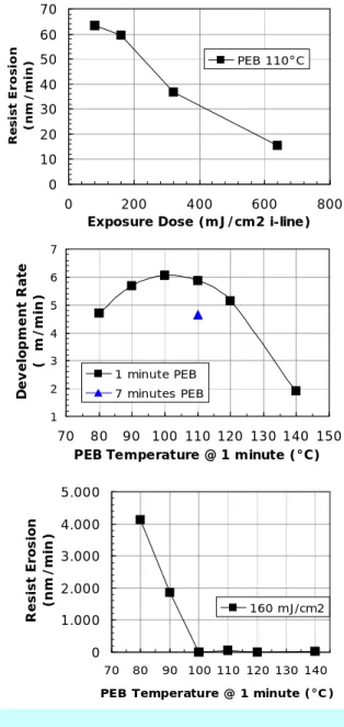
Resist Erosion and Development RateWith a sufficient post exposure bake of 110°C for one min-ute, the parameter limiting the extent of cross-linking is the
exposure dose. As the figure right-hand, top shows, the erosion of unexposed resist (corresponding to the dark ero-sion of positive resists) in developer (here: AZ® 726mif)
drops with the exposure dose. It has to be considered, that too high exposure doses reduce the lateral resolution by light scattering in the resist or, respectively, between resist and mask. Therefore, the exposure dose recommended in the technical data sheet should be considered as a starting point for individual process optimization.
The development rate as a function of the PEB conditions (fig. right-hand, centre) reveals a maximum near the post exposure bake temperature and –time recommended in the technical data sheet (110°C for 1 minute).
The strong impact of the PEB temperature on a sufficiently high cross-linking shows the figure right-hand, bottom: Be-low 100°C, the resist erosion in developer strongly increases, with the resist contrast drops towards zero. For the sake of a stable process window, a PEB at 110°C on a hotplate is rec-ommended. If an oven is used instead of a hotplate, it has to be considered that it takes a certain delay until the resist reaches the desired final temperature. Therefore, fir oven processes, the temperature or time for the PEB may be ad-justed towards higher values.
In contrast to the softbake, the optimum PEB temperature and –time does not depend on the resist film thickness. How-ever, during PEB a certain amount (dependent from the resist film thickness) of the remaining solvent evaporates thus re-ducing the resist film thickness. This has to be considered when determining the resist erosion in developer or the de-velopment rate.
n
Adjusting the UndercutThe exposure dose determines the part of the resist cross-linked after the post exposure bake (PEB). Since AZ® nLOF 20xx does not bleach during exposure, the possible penetration depth during exposure is
limited and can only be extended by – compared with AZ® positive resists - much higher exposure doses.
Temperature and time of the PEB vary the depth profile of cross-linking. For the sake of a high contrast, 110°C for 1 minute is recommended for this step.
When the structures are cleared, the amount of over-development defines how much the undercut is pronounced. However, this adjustment is only possible if not the whole resist film is through-exposed, but a certain resist part near the substrate remains unexposed.
Fig. right-hand: The upper 9 μm of the 22 μm re-sist film thickness are cross-linked by exposure and subsequent PEB. Below 9 μm, the i-line (365 nm) in-tensity drops below 1% of the incident inin-tensity, which is not sufficient for cross-linking of resist closer to the substrate. The borderline between the cross-linked and developable resist can easily be seen in cross-section (fig. right-hand) and shifted via the exposure dose within certain limits.
Fig. overleaf: The high transparency of AZ® nLOF
20xx allows a control of the undercut with optical microscopy. In the left picture, the focus is near the resist surface, while in the right picture, the focus meets the substrate.
22 μm resist film thickness Exposed and
cross-linked resist Development time Cross-section 0 1.000 2.000 3.000 4.000 5.000 70 80 90 100 110 120 130 140
PEB Temperature @ 1 minute (°C)
R e si st E ro si o n (n m / m in ) 160 mJ/cm2 1 2 3 4 5 6 7 70 80 90 100 110 120 130 140 150
PEB Temperature @ 1 minute (°C)
D e v e lo p m e n t R a te ( μ m / m in ) 1 minute PEB 7 minutes PEB 0 10 20 30 40 50 60 70 0 200 400 600 800
Exposure Dose (mJ/cm2 i-line)
R e si st E ro si o n (n m / m in ) PEB 110°C
MicroChemicals GmbH Ulm – www.microchemicals.com - [email protected]
n
Adjusting the Undercut at 17.9 μm Resist Film ThicknessWith ‘fast processing’ (single-coating, short delays) as a precondition, in the following the undercut has been adjusted by varying the exposure dose, the post exposure bake temperature, and the over-development:
Coating: Ramp +3000 rpm/s, 3000 rpm for one second, ramp -3000 rpm/s Delay: 5 minutes at room temperature for resist film homogenization 1st softbake: 30 seconds at 100°C hotplate for subsequent edge bead removal Edge bead removal: approx. 10 seconds at 500 rpm with AZ® ebr Solvent
Softbake: 10 minutes at 100°C hotplate Film thickness: 17.9 μm
Exposure
Dose: 500 mJ/cm2 i-line 500 mJ/cm2 i-line 1.000 mJ/cm2 i-line 1.000 mJ/cm2 i-line PEB 110°C 2 minutes 130°C 2 minutes 110°C 2 minutes 130°C 2 minutes
Develop-ment 4 min AZ® 826mif 7 min AZ® 826mif 4 min AZ® 826mif 9 min AZ® 826mif
A ft er t h ro u gh -d ev el o pm en t dimen-sional
Accuracy* +3.2 μm (upper edge) +21 μm (upper edge) +11 μm (upper edge) +38 μm (upper edge) additional 2 min AZ® 826mif 4 min AZ® 826mif 2 min AZ® 826mif 5 min AZ® 826mif
A ft er o v e r -d ev el o pm en t dimen-sional
Accuracy* +1.1 μm (upper edge) +11 μm (upper edge) +2.8 μm (upper edge) +33 μm (upper edge) Removal approx. 1 minute NMP 20°C approx. 1 minute NMP 20°C approx. 10 minutes NMP 20°C approx. 10 minutes NMP 20°C *Half difference between resist pattern width after development and mask space
Upper resist edge Linear undercut Total undercut (approx. 24 µm) Focus:
MicroChemicals GmbH Ulm – www.microchemicals.com - [email protected]
n
Thermal StabilityCross-linked (exposed and subsequently baked) AZ® nLOF 20xx is thermally stable and does not soften
even at temperatures >200°C. However, in case of thick resist films or/and low exposure doses, the cross-linked resist part sits on top of resist not cross-linked. As a consequence, the total resist structure will suffer from softening of this substrate-near thermally unstable resist part (fig. below, resist film thick-ness = 22 µm).
One way to stabilize even thick films of AZ® nLOF is an extended 1st exposure. However, this will
re-duce the lateral resolution and require unreasonable high exposure times in case of films exceeding 10-15 μm.
A better way to improve the thermal sta-bility of thick AZ® nLOF 20xx films is a
flood exposure (without mask) after development with subsequent post expo-sure bake at 110°C for 1 minute. As the figure right-hand reveals, light scattering illuminates also the resist undercut which allows crosslinking of the total resist sur-face making the whole structure ther-mally stable to some extent. The moder-ate softening of the resist structure still allows e.g. lift-off. For this step, a flood exposure i-line dose of approx. 1 J/cm2
is recommended, which corresponds to approx. two minutes of exposure using a standard mask-aligner with 350W Hg-bulb.
n
‚Mouse-Bites’ in developed StructuresIf developed resist structures show μ m-sized irregularities (‚mouse-bites’, figures right-hand), in most cases the origin is
light scattering between mask and the resist surface. Assisted by the high con-trast of AZ® nLOF 20xx, the slight
inho-mogeneities in the exposure dose signifi-cantly transfer into the development rate of the resist.
Therefore, much care has to be taken to yield a close contact between mask and resist by avoiding particles and/or
bubbles in the resist film as well as a proper edge bead removal especially in case of thick resist films and/or rectangu-lar shaped substrates.
Exposed and cross-linked resist After development Not cross-linked Exposed and cross-linked After hardbake @ 170°C
Not cross-linked → ther-mally softened
Developed + flood exposed, after hardbake @ 170°C
MicroChemicals GmbH Ulm – www.microchemicals.com - [email protected]
n
Resist Film ThicknessA spin curve (= resist film thickness after softbake as a function of the spin speed) is given in the AZ® nLOF 2000 technical data
sheet of the manufacturer Clariant.
The diagram right-hand shows the resist film thickness attained at 4.000 rpm as a func-tion of the dilution ratio of AZ® nLOF 2070
with PGMEA (=AZ® ebr solvent). The
soft-bake was performed at 100°C on an contact hotplate for 5 minutes. The values on the X-axis correspond to the amount of AZ® ebr
solvent (in grams) to be added to 100 grams AZ® nLOF 2070.
n
Solubility / Stripping of the Resist Film after ProcessingThe solubility of cross-linked AZ® nLOF 20xx in organic solvents is generally very low. Therefore, the
stripping of the processed resist film is much more a lifting of the whole resist film from the substrate with
suited media:
Acetone solves unexposed AZ® nLOF 20xx as long as the temperatures applied keep below approx.
170°C. Beyond this temperature, thermal (without previous exposure) cross-linking of the resist film strongly reduces the solubility. Exposed and cross-linked (PEB >90°C) AZ® nLOF 20xx is NOT soluble in
acetone any more. However, if the limited penetration depth of i-line keeps the substrate-near resist un-exposed (and, therefore, not sufficiently cross-linked by the subsequent PEB), acetone can diffuse through the resist and lift the resist film after a certain delay.
For the same reason, AZ® 100 Remover is only a good stripper under certain conditions: Generally, its
suitability dependent from the processing of the resist can be transferred from the feasibility of acetone described in the previous section.
NMP (N-Methylpyrrolidone) is very well suited for stripping of even completely cross-linked AZ®
nLOF 20xx. Dependent from the temperature of the PEB – or, if applied, the hardbake – NMP lifts the re-sist film in between few seconds (in case of a 110°C PEB or hardbake) or few minutes (150°C hardbake) from the substrate.
If even NMP is not able to remove the resist film under standard conditions, either i) heating the NMP, or/and ii) ultrasonic treatment, or/and iii) a lower exposure dose in order to keep a substrate-near resist part without cross-linking may help.
0 1 2 3 4 5 6 0 25 50 75 100
X (100 gram AZ® nLOF 2070 + X gram AZ® ebr solvent)
R e s is t fi lm t h ic k n e ss a ft e r s o ft b a k e i n μ m (s p in p ro fi le : ra m p 2 5 0 0 r p m / s, t h e n 4 0 0 0 rp m f o r 3 0 '')