Semi-Active Control of Structures Using
a Neuro-Inverse Model of MR Dampers
A. Khaje-Karamodin
1, H. Haji-Kazemi
1;, A.R. Rowhanimanesh
2and
M.R. Akbarzadeh-Tootoonchi
2Abstract. A semi-active controller-based neural network for a 3 story nonlinear benchmark structure equipped with a Magneto Rheological (MR) damper is presented and evaluated. An inverse neural network model (NIMR) is constructed to replicate the inverse dynamics of the MR damper. A Linear Quadratic Gaussian (LQG) controller is also designed to produce the optimal control force. The LQG controller and the NIMR models are linked to control the structure. The eectiveness of the NIMR is illustrated and veried using the simulated response of a full-scale, nonlinear, seismically excited, 3-story benchmark building excited by several historical earthquake records. The semi-active system using the NIMR model is compared to the performance of an active LQG and a Clipped Optimal Control (COC) system, which is based on the same nominal controller as used in the NIMR damper control algorithm. Two passive control systems are also considered and compared. The results demonstrate that by using the NIMR model, the MR damper force can be commanded to follow closely the desirable optimal control force. The results also show that the control system is eective, and achieves better performance than active LQG and COC system. The optimal passive controller performs better than the NIMR. However, the performance of NIMR will be improved if a more eective active controller is replaced by a LQG controller.
Keywords: Structural control; Semi-active; Neural network; Nonlinear; MR damper.
INTRODUCTION
The Magneto Rheological (MR) damper is generating a great interest among researchers in the semi-active control of civil structures [1-4]. The MR damper is a smart semi-active control device that generates force to a given velocity and applied voltage. The MR damper is lled with a special uid that includes very small polarizable particles, which can change its viscosity rapidly from liquid to semi-solid and vice versa by adjusting the magnitude of the magnetic eld produced by a coil wrapped around the piston head of the damper. The magnetic eld can be tuned by varying the electrical current sent into the coil. When no current is supplied, the MR damper behaves similar
1. Department of Civil Engineering, Ferdowsi University of Mashhad, Mashhad, P.O. Box 9177948944-1111, Iran. 2. Department of Electrical Engineering, Ferdowsi University of
Mashhad, Mashhad, P.O. Box 9177948944-1111, Iran. *. Corresponding author. E-mail: [email protected] Received 20 November 2007; received in revised form 9 August 2008; accepted 1 November 2008
to an ordinary viscous damper, whereas its uid starts to change to semi-solid as the current is gradually sent through the coil. Consequently, semi-active controllers using MR dampers are powerful devices that enjoy the advantages of passive devices with the benets of active control. Additionally, they are inherently stable, reliable and relatively cost-eective and require small activation power.
One challenge in the use of semi-active tech-nology is in developing nonlinear control algorithms that are appropriate for implementation in full-scale structures. Numerous control algorithms have been adopted for semi-active systems. These algorithms are either conventional methods based on mathematical formulation [1-4] or intelligent methods based on neural networks or fuzzy logic [5-7].
Interest in a new class of computational intel-ligence systems known as Articial Neural Networks (ANNs) has grown in the last few years. This type of network has been found to be a powerful compu-tational tool for organizing and correlating informa-tion in ways that have been proven to be useful for
solving certain types of problem that are complex and poorly understood. The applications of ANNs to the area of structural control have grown rapidly through system identication, system inverse identication or controller replication [5-6].
In addition to using the Linear Quadratic Reg-ulator (LQR) method, Chang and Zhou [8] manipu-lated recurrent neural networks to emulate the inverse dynamics of the MR damper to predict the required voltage for a full-state feedback closed-loop system. This model was used to control a three-storey building subjected to the El Centro earthquake record. Simi-larly, Bani-Hani et al. [5] proposed neural network to simulate the inverse model of an MR damper in a 6-story base-isolated building subjected to earthquake forces.
In this paper, a NN model is used to emulate the inverse dynamics of the MR damper. This NN model (NIMR) is trained based on the input-output data generated using the phenomenological model proposed by Dyke et al. [9]. The model calculates a voltage signal based on a few previous time steps of velocity, damper force and desirable control force. This NN model is used to calculate voltage signals to be input to the MR damper so that it can produce desirable optimal control forces that are estimated by the LQG control algorithm. In principle, these control forces can come from any control algorithm that requires an explicit use of control forces to mitigate response. The eectiveness of the NIMR is illustrated and veried using the simulated response of a full-scale, nonlinear, seismically excited, 3-story benchmark building excited by several historical earthquake records. The semi-active system using the NIMR model is compared to the performance of an active LQG and a Clipped Optimal Control (COC) system, which are based on the same nominal controller used in the NIMR control algorithm. Additionally, two passive control systems are also considered and compared.
THREE-STORY BENCHMARK BUILDING The benchmark 3-story building used for this study was designed for the Los Angeles region, as dened by Ohtori et al. [10] in the problem denition paper. The building is 36.58 m by 54.87 m in plan and 11.89 m in height. Two far-eld and two near-eld historical ground motion earthquake records are selected for study: El Centro (1940), Hachinohe (1968), Northridge (1994) and Kobe (1995). Control actuators are located on each oor of the structure to provide forces to adjacent oors. Because the actuator capacity is limited to a maximum force of 1,000 kN, three actuators are employed at the rst oor and two actuators at both the second and the third oors to provide the required larger forces. Three sensors for acceleration measurements are used for feedback in the control system on the rst, second and third oors.
CONTROL STRATEGY
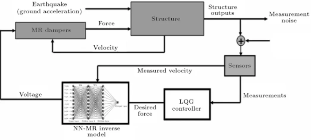
Figure 1 illustrates the proposed control strategy. There is basically no restriction on the type of control algorithm that should be used, as long as it calculates a desirable control force, fd, based on response and/or
excitation. The desirable control force and the response of the building are passed into the inverse NN model. This NN model emulates the inverse dynamics of the MR damper. The output of this inverse NN model is the voltage required to produce the desirable control force under the current response condition. This voltage is input to the MR damper, which then produces force facting on the building.
MR Model
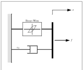
Adequate modeling of the control devices is essential for accurate prediction of the behavior of the con-trolled system. The simple mechanical model shown
Figure 2. Mechanical model of MR damper.
in Figure 2 was developed and shown to accurately predict the behavior of the MR damper over a wide range of inputs [9]. This phenomenological model was developed based on a previous model used for a MR damper [11]. The equations governing the force, f, predicted by this model are as follows:
f = c0_x + z; (1)
_z = _xjzjzjn 1 _xjzjn+ A _x; (2)
where z is the evolutionary variable that accounts for the history dependence of the response. The model parameters depend on the voltage, v, to the current driver as follows:
= a+ bu; (3a)
c0= c0a+ c0bu; (3b)
where u is given as the output of the rst-order lter:
_u = (u v): (4)
Equation 4 is used to model the dynamics involved in reaching rheological equilibrium and in driving the electromagnet in the MR damper [9]. This MR damper model is used herein to model the behavior of the MR damper. The parameters of the MR damper were selected so that the device has a capacity of 1,000 kN, as follows:
a = 1:0872e5 N/cm;
b=4:9616e5 N/(cm V);
c0a= 4:40 N s/cm;
c0b= 44:0: N s/(cm V);
n = 1; A = 1:2; = 3 cm 1;
= 3 cm 1; = 50 s 1:
Neural Network Inverse Dynamics of MR Damper (NIMR)
The MR damper model discussed earlier in this paper estimates damper forces based on the inputs of the reactive velocity and the issued voltage as described by Equations 1 to 4. The damper velocity is the same as the velocity of the oor to which the damper is connected. Thus, the voltage signal is the only parameter that can be modied to control the damper force to produce the required control force. The control algorithm, LQG, estimates the required optimal control force but the MR damper force is controlled by voltage. In such a case, it is essential to develop an inverse dynamic model that predicts the corresponding control voltage to be sent to the damper, so that an appropriate damper force can be generated. Unfortunately, due to the inherent nonlinear nature of the MR damper, a mathematical model for its inverse dynamics is dicult to obtain. Because of this reason, a feed-forward back-propagation neural network is constructed to copy the inverse dynamics of the MR damper (Figure 3). This model is denoted as NIMR. This neural network model is trained using input-output data generated analytically using the simulated MR model based on Equations 1 to 4. This NIMR calculates the voltage signal based on the current and few previous histories of measured velocity and desirable control force. Then, the voltage signals are sent to the MR damper so that it can generate the desirable optimal control forces.
Training the NIMR requires the compilation of input-output data. To completely identify the un-derlying MR system model, the data must contain information about the entire operating range of the system. Here, in this study, the velocity and voltage are generated randomly using band limited white Gaussian noise. The generated forces are results of the MR model described in Equations 1 to 4. The sampling rate of the training data was 200 Hz for 30 s periods,
Figure 3. NN of inverse dynamics of MR damper (NIMR).
which resulted in 6000 patterns for training, testing and validation (Figure 4). The next step is to select the network architecture. To do so, it is required to determine the numbers of inputs, outputs, hidden layers and nodes in the hidden layers, which is usually done by trial and error. The most suitable input data for our case was found to be the current and four previous histories for the velocity and the force. Also, two hidden layers, each layer with ten nodes, were adopted as one of the best suitable topologies for the NIMR, as can be seen in Figure 3. The log-sigmoid (ranging from 0 to 1) activation function is used for the hidden layers and the linear function for the output layer, which represents the voltage. 3000 patterns of the provided data were chosen for training which required 1000 training epochs to achieve a Mean-Square-Error (MSE) of 1e-03.
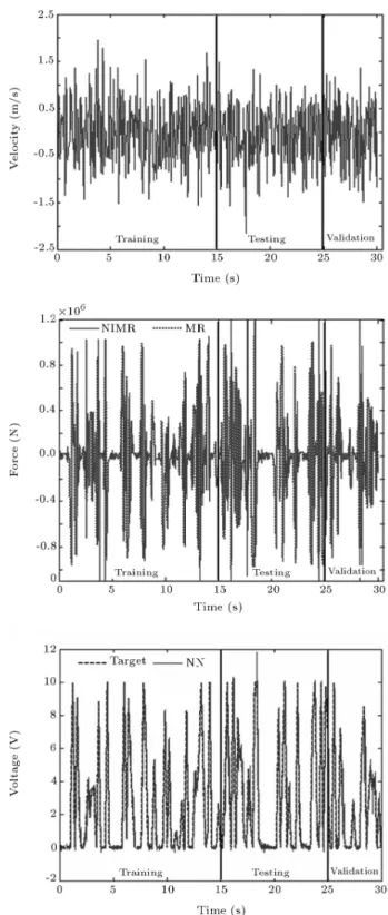
The training is carried out upon the generated data using the Levenberg-Marquardt algorithm [12], which is encoded in Neural Networks Toolbox in MAT-LAB [13] under the `trainlm' routine. Finally, testing and validation of the trained network is investigated using a few sets of new data for a 30 s period. Figure 5 shows the training testing and validation velocity, forces and voltage records used in constructing the NIMR model. Additionally, Figure 5 compares the forces computed by the MR damper model based on the generated random voltage to the forces computed by the MR damper model based on the predicted voltages by NIMR. Moreover, the predicted voltage record from the NIMR is compared to the randomly generated targets and presented in Figure 5. It is clear that, in general, the predicted voltages are reasonably close to the target voltages. The near perfect match in the training region indicates that the NIMR model is well trained. Henceforth, the NIMR model will be used to compute the required voltage for a specic force and velocity. This will alleviate problems resulting when using a control algorithm that computes only the optimal control forces.
Figure 4. Training of NIMR.
Figure 5. Training, testing and validation data.
Control Performance
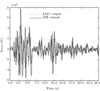
The performance of the NIMR neural network is checked according to comparison of the force generated by the MR damper to the ideal force estimated by the LQG controller. Figure 6 shows the force gen-erated by the MR damper at the rst oor of the building for the El Centro earthquake, commanded by
Figure 6. Comparison of the force generated by MR damper to the ideal force (LQG).
NIMR, as compared to the ideal force estimated by the LQG controller. It can be seen that the damper forces follow the target optimal control force quite closely.
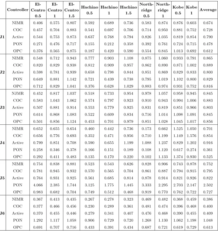
The performance of the controller is also in-vestigated based on the evaluation criteria specied (J1-J6) for the 3-story nonlinear benchmark build-ing [10]. These criteria, which are briey presented in Table 1, are calculated as a ratio of the controlled and the uncontrolled responses, in most cases. Ten earthquake records are used in the simulation, using the original four earthquake records with dierent intensities. These records are the El Centro and Hachniohe earthquake records with 0.5, 1.0, and 1.5 intensity and Northridge and Kobe earthquake records with 0.5 and 1.0 intensity. To make a comparison, an active control system and semi-active Clipped-Optimal Control (COC) system [4] are also designed. Moreover, to compare the performance of the proposed method, two passive control systems have been considered. Both passive control systems use the MR damper in passive mode (constant voltage). The rst passive system designated as Passive On (PON) uses the MR
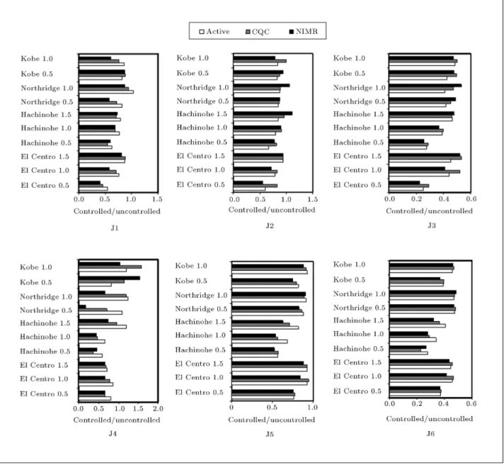
damper with maximum voltage (10 Volts). In the second passive system, named Optimal Passive Control (OPC), the voltage of the MR damper in each story is dened as an optimization problem. The objective of the optimization is to minimize the average of the performance indices, J1-J6, under the El Centro earthquake. Table 2 presents the evaluation criteria as the ratio of the controlled response to the uncontrolled response for each earthquake record, individually, for active LQG, COC, PON, OPC and the proposed control algorithms. Figure 7 also shows the relative performance of these algorithms for criteria J1, J2, J3, J4, J5 and J6. The results show that the NIMR controller performs better than COC and active control in reducing the peak drift ratio (J1). For the peak level acceleration (J2), the NIMR controller has been able to perform better than COC, but the LQG controller is more eective. The peak base shear force criterion (J3) for NIMR is smaller than COC but greater than active LQG. In terms of norm drift ratio (J4), the performance of NIMR is better than COC and LQG. The NIMR is more eective than COC and LQG in the reduction of norm level acceleration (J5) and the norm base shear force (J6). The results also show that PON performs better to reduce the drift, but increases the acceleration of the building. It is also seen that OPC performs better than other controllers to reduce the drift and acceleration of the building. However, it should be noted that the primary controller used in the proposed semi-active control method (LQG) is the optimal controller for linear systems. The 3 story building in this paper is a nonlinear system and the LQG controller is not an optimal controller for this building. So, if a more eective active controller is used as a primary controller, the semi-active controller will be more eective.
CONCLUSION
In this study, neural networks are used to model the inverse dynamics of MR damper. The inputs to the NN models are a few time steps of structural velocities and damper forces. The output is the command voltage
Table 1. Performance criteria for seismically excited nonlinear building. Interstory Drift Ratio Level Acceleration Base Shear J1= max
El centro Hachino Northridge Kobe ( max t;i
jdi(t)j
hi
max
)
J2= max El centro
Hachino Northridge
Kobe
max
t;ijxai(t)j
xmax
ai
J3= max El centro Hachino Northridge Kobe 8 > < > : max t P
i mxai(t)
Fmax b 9 > = > ; Normed Interstory Drift Ratio Normed Level Acceleration Normed Base Shear
J4= max El centro Hachino Northridge Kobe ( max t;i
kdi(t)k
hi
kmaxk
)
J5= max El centro
Hachino Northridge
Kobe
max
t;ikxai(t)k
kxmax a k
J6= max El centro Hachino Northridge Kobe 8 > < > : max i
Pi mixai(t)
kFmax b k 9 > = > ;
Table 2. Performance criteria for active, Clipped Optimal Control (COC), NIMR, PON and OPC algorithms. Controller
El-Centro
0.5
El-Centro
1
El-Centro
1.5
Hachino 0.5
Hachino 1
Hachino 1.5
North-ridge
0.5
North-ridge
1
Kobe 0.5
Kobe
1 Average NIMR 0.406 0.575 0.807 0.592 0.689 0.736 0.583 0.874 0.876 0.603 0.674
COC 0.457 0.704 0.883 0.541 0.697 0.706 0.714 0.950 0.881 0.752 0.728 J1 Active 0.544 0.753 0.873 0.637 0.768 0.794 0.826 1.035 0.819 0.854 0.790 PON 0.271 0.476 0.717 0.155 0.212 0.358 0.392 0.761 0.724 0.715 0.478 OPC 0.376 0.565 0.875 0.187 0.420 0.590 0.554 0.845 1.013 0.692 0.612 NIMR 0.548 0.712 0.943 0.777 0.903 1.108 0.875 1.060 0.933 0.791 0.865 COC 0.820 0.829 0.938 0.812 0.909 0.957 0.862 0.890 0.871 1.002 0.889 J2 Active 0.598 0.781 0.939 0.658 0.798 0.844 0.851 0.869 0.829 0.833 0.800 PON 0.649 0.881 1.142 0.721 0.439 0.738 0.795 1.019 1.102 0.800 0.829 OPC 0.712 0.829 1.041 0.376 0.628 1.029 0.883 0.974 0.931 0.752 0.816 NJMR 0.452 0.817 1.037 0.518 0.733 0.954 0.978 1.057 0.958 0.945 0.845 COC 0.583 1.043 1.062 0.574 0.797 0.923 0.910 0.943 0.994 1.006 0.883 J3 Active 0.507 0.881 0.914 0.553 0.779 0.925 0.831 0.819 0.851 0.966 0.803 PON 0.614 0.868 1.083 0.522 0.609 0.834 0.716 1.014 1.098 1.091 0.845 OPC 0.501 0.856 1.124 0.453 0.701 0.979 0.851 1.028 1.045 1.017 0.856 NIMR 0.652 0.655 0.654 0.460 0.442 0.736 0.173 0.662 1.525 1.050 0.701 COC 0.656 0.776 0.693 0.352 0.471 0.956 0.710 1.199 1.149 1.576 0.854 J4 Active 0.799 0.851 0.708 0.590 0.655 1.199 1.088 1.237 0.829 1.202 0.916 PON 0.258 0.346 0.378 0.166 0.151 0.189 0.108 1.120 0.617 0.274 0.361 OPC 0.292 0.411 0.483 0.135 0.170 0.220 0.102 1.133 1.374 0.930 0.525 NIMR 0.754 0.838 0.881 0.523 0.543 0.626 0.828 0.906 0.743 0.878 0.752 COC 0.781 0.945 0.932 0.570 0.565 0.704 0.861 0.887 0.794 0.915 0.795 J5 Active 0.764 0.931 0.925 0.561 0.685 0.814 0.878 0.914 0.821 0.926 0.822 PON 4.066 2.385 1.744 3.125 1.775 1.445 3.333 2.295 2.703 2.147 2.502 OPC 0.983 0.682 0.704 0.749 0.512 0.468 0.919 0.770 0.762 0.722 0.727 NIMR 0.367 0.413 0.435 0.267 0.278 0.323 0.469 0.482 0.368 0.459 0.386 COC 0.377 0.466 0.456 0.230 0.289 0.361 0.481 0.474 0.396 0.468 0.400 J6 Active 0.370 0.455 0.446 0.279 0.341 0.407 0.476 0.468 0.390 0.455 0.409 PON 1.292 1.117 1.058 0.906 0.729 0.720 1.268 1.130 1.062 1.198 1.048 OPC 0.691 0.707 0.716 0.433 0.391 0.434 0.687 0.721 0.619 0.729 0.613
to the MR damper. These NN models estimate the voltage that is required to produce a target control force calculated from some optimal control algorithms. The main objective of this development is to explore whether the semi-active MR damper can be used to produce optimal control forces.
A 3-story nonlinear benchmark building has been used for study. The results illustrate that it is possible to incorporate the NN models into the control strategy and, hence, operate the damper in an active mode.
In general, the forces generated by the MR damper can follow those caculated from the optimal control algorithms. The performance of the controller has been checked, based on the evaluation criteria specied (J1-J6) for the benchmark building. The results show that the mean of the average indices, J1 to J6, for dierent earthquake records are 0.768, 0.825, 0.825, 1.010 and 0.691, respectively, for NIMR, COC, LQG, PON and OPC methods. It can be concluded that the NIMR controller performs better than the COC, LQG
Figure 7. Comparison of performance criteria J1-J6 of NIMR to active and COC method.
and PON, but the OPC performs better than other controllers.
REFERENCES
1. Casciati, F., Magonette, G. and Marazzi, F., Technol-ogy of Semi-Active Devices and Application in Vibra-tion MitigaVibra-tion, John-Wiley (2006).
2. Dyke, S.J., Spencer, B.F., Jr., Sain, M.K. and Carlson, J.D. \Seismic response reduction using magnetorheo-logical dampers", Proc., IFAC World Congr., pp. 145-150 (1996c).
3. Dyke, S.J., Spencer, B.F., Jr., Sain, M.K. and Carlson, J.D. \Modeling and control of magnetorheological dampers for seismic response reduction", Smart Mat. and Struct., 5, pp. 565-575 (1996d).
4. Yoshida1, O. and Dyke, S. \Seismic control of a nonlinear benchmark building using smart dampers", Journal of Engineering Mechanics (ASCE), 130(4), pp. 386-392 (2004).
5. Bani-Hani, K.A., Mashal, A. and Sheban, M.A. \Semi-active neuro-control for base-isolation system using magnetorheological (MR) dampers", Earthquake En-gng. Struct. Dyn., 35, pp. 1119-1144 (2006).
6. Jung, H.J., Lee, H.J., Yoon, W.H., Oh, J.W. and Lee, I.W. \Semiactive neurocontrol for seismic response reduction using smart damping strategy", Journal of Computing in Civil Engineering, 18(3), pp. 277-280 (2004).
7. Choi, K.M., Cho, S.W., Jung, H.J. and Lee, I.W. \Semi-active fuzzy control for seismic response
reduc-tion using magnetorheological dampers", Earthquake Engng Struct. Dyn., 33, pp. 723-736 (2004).
8. Chang, C.C. and Zhou, L. \Neural network emulation of inverse dynamics for a magnetorheological damper", Journal of Structural Engineering, 128(2), pp. 231-239 (2002).
9. Dyke, S.J., Yi, F. and Carlson, J.D. \Application of magnetorheological dampers to seismically excited structures", Proc., Int. Modal Anal. Conf., Bethel, Conn (1999).
10. Ohtori, Y., Christenson, R.E., Spencer, B.F., Jr. and Dyke, S.J. \Benchmark control problems for
seis-mically excited nonlinear buildings", J. Eng. Mech., 130(4), pp. 366-387 (2004).
11. Spencer, B.F., Jr., Dyke, S.J., Sain, M.K. and Carlson, J.D. \Phenomenological model of magnetorheological damper", J. Engrg. Mech., ASCE, 123(3), pp. 230-238 (1997).
12. Hertz, J., Krogh, A. and Palmer, R.G., Introduction to the Theory of Neural Computation, Addison-Wesley Publishing Company, Boston, MA (1993).
13. The Math Works Inc. MATLAB 7.0, Natick, MA (2006).