114
Mathematical and Software Engineering, Vol. 2, No. 2 (2016), 114-121. Varεpsilon Ltd, http://varepsilon.com
Design of Dual Band Microstrip Antenna Using
Reactive Loading Technique
1
Jeffrey C. Saturday,
2Kufre M. Udofia,
3Afolayan J. Jimoh
1,2,3Department of Electrical/Electronic and Computer Engineering, University of Uyo, Uyo, Akwa Ibom State, Nigeria
Correspondence Author: [email protected]
Abstract
The need in most communication devices to have two separate operating frequencies for a variety of applications cannot be over emphasized. Microstrip antennas, as part of its inherent characteristics, have the ability to resonate at multiple frequencies depending on the design requirement. In this paper, the design of a dual band microstrip antenna for bandwidth enhancement using reactive loading technique is presented. The designed antenna is of rectangular shape, planar and compact for application in mobile devices. The antenna has a miniature size of 44×41×1.6 mm , which resonated at a return loss of -19.619 and voltage standing wave ratio (VSWR) of 1.303 at 2.4 GHz, and -17.55 dB and VSWR of 1.301 at 5.2 GHz. The results show that the antenna has a corresponding bandwidth of 124.6 MHz and radiation efficiency of 86.1 % at 2.4 GHz and 119.8 MHz and radiation efficiency of 77.4 % at 5.2 GHz. The substrate used in the proposed antenna is the flame retardant/resistant four (FR-4) with a dielectric constant of 4.4 and a loss tangent of 0.023.
Keywords: Antenna; Slot Patch; Dual Frequency; Miniature; Inset Feed
1 Introduction
Rapid developments of various Wireless Local Area Network (WLAN) protocols have sparked the requirements for miniaturized multi-band antennas. Today, the most wide spread WLAN protocols are IEEE 802.11b/g, which utilizes the 2.4 GHz ISM band (2.4–2.485 GHz), and IEEE 802.11a which employs the 5 GHz U-NII band and ISM band (5.15–5.825 GHz) [1]. Small size and light weight antennas are required for portable cellular phones. Microstrip antennas (MSAs) are small in size, low-cost and easy to mount and these good features make them excellent candidates for portable cellular phones [2]. The efficiency realized when one antenna works in different frequencies is more than the efficiency realized when several antennas are used for each frequency band. There are numerous devices that require the dual-band wireless antenna. Wi-Fi is an example of Internet service that utilizes the dual-band networks. For instance, computers with wireless cards are in most cases Wi-Fi compatible, where wireless card transmits to a wireless router, which is connected to a network, cable modem or DSL modem [3].
115
flexibility of mounting the antenna both on planar and non-planar surfaces aside using for mobile devices.
The use of multiple patches was suggested by [5] but the ripples as observed from the return loss plot when used in practical application can interfere with adjacent frequencies. Slotted square patch with inset feed was proposed by [6], it was supposed to cover 2.4 GHz, 5.2 GHz and 5.8 GHz respectively but it fell short as it only managed to cover only 2.6 GHz and 5.2 GHz from the result obtained. Another Square slotted patch with quarter-wave edge feed was proposed by [8] which resonated at 2.5 GHz and 5 GHz as designed.
2 Conventional Techniques for Achieving Dual Band Frequency
a) Use of orthogonal mode: These antennas are characterized by two resonances with orthogonal
polarizations. The drawback on this method is that the two dissimilar frequencies excite two orthogonal polarizations. These antennas are simultaneously match the input impedance at the two frequencies by using a single feed structure.
b) Use of multiple patches: The dual band operation can be achieved through multiple radiating elements, whereby each of the radiating elements supports strong currents in addition to radiation at the resonance. This category includes multi-layer stacked patches that can use patches of various shapes. At the two frequencies, the multi-layer stacked patch antennas operate with the same polarization.
c) Use of reactive loading: A very popular technique for obtaining a dual band behaviour is to introduce a reactive loading to a single patch. The easiest method is connecting a stub to one radiating edge, so as to introduce an additional resonant length that is facilitate the second operating frequency. This is the technique adopted in this paper.
3 Design Calculations for Single Rectangular Patch Antenna
1. The first step in designing rectangular patch antenna is to specify the resonant frequency (f ), substrate relative permittivity (ε ) and substrate thickness (h). When h satisfies the criterion in equation 1, then the surface waves loss can be neglected [10]:
ℎ ≤ 0.3
√ (1) λ = (2)
Where h is the height of substrate, is the dielectric constant, wavelength in free space (air), c = speed of light = 3× 10# m/s, loss tangent, tan & = 0.023
Flame retardant 4 (FR-4) substrate is chosen for this design with substrate relative permittivity
ε of 4.4 and height, h of 1.6mm. The chosen substrate height is a good approximation since the proposed antenna is a narrow band antenna.
2. The width (Wp) of the patch is calculate as follows[11];
'(= )
*+ (3) 3. Calculate the effective dielectric constant ,-- thus ;
ε . = *++ 0+11 − 1254
67 089
(4)
for 546> 1
116 ∆=
4 = 0.412
( @AA*B. )DE6F *B. GHI ( @AA0B. J# )DE6F *B.#I
(5)
5. Calculate the value of the length of the patch Lp thus,
L=
√ − 2∆Lp (6) 6. Calculate the notch width, g using the equation
L = × +BMN ×H.GJ × +BMN
O @AA (7)
7. Calculate the resonant input resistance Rin thus;
RQ(y = yS) = (T8* T+ 89)cos W=X6YZ (8) The equation for the characteristic impedance Zo is given as;
ZS \
O_ @AA]^ `Q1 aF
EA* EAbF7 EAFc+ 89^d
O_ @AADEAF*+. e * B.GGf `Q EAF*+.HHH I EAFg+
(9)
In this design, the ratio, 54A= +.G.e#= 1.863 > 1, so the second expression in Equation 9 applies.
Rin(edge) = (T +
8∓ T89) (10) In order to evaluate the input resistance, other parameters such as wave number k, input current I1, input conductance G1 and mutual conductance G12 have to be known. Hence,
k = (11) I1 = -2 + cos(X) + XSi(X) + l Q (m)m (12)
X = kWp (13)
G1 = + Bn8 9 (14)
G12 = + Bo+ 9 p q
l Q (rE69 Sls)
Sls t JS(kLvsinθ)sin θdθ o
B (15)
For the design in this paper, inset feed technique is used with a chosen input impedance of 50 Ω. 8. Calculate the inset feed recessed distance y0 and the width of the transmission line Wf thus;
Z0 = Rin(edge) {|} (~o
•€B) (16)
€B = ~o• {|}0+q)‚ƒ„(…†‡…)•^ t (17) According to [12], the width ('-) of the transmission line is calculated thus:
B = GBo9
•ˆ√‰Š
'- = o‹ × Œ
• − 1 − ln•2 × • − 1• + ‰Š0+ ‰Š …
… × ln•• − 1• + 0.39 −B.G+‰Š “ for
5A
4 > 2; (18)
9. Calculate the ground plane dimensions as follows;
The length of the ground plane (Lg) is:
Lg = 6h + Lp (19)
The width of the ground plane is:
117
4 Results and Discussion
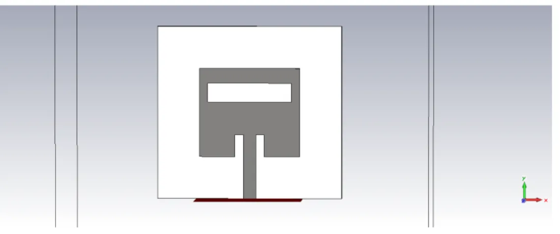
The antenna is simulated using CST Microwave. The design parameters used in the simulation are shown in Table 1 while geometry of dual band microstrip antenna is given in Fig. 1 and Fig. 2.
Table 1: The Design Parameters for The Dual Band Antenna
Variables Wg Lg Wp Lp Wf Lf g yo C
Value(mm) 44 41 24 21 2.96 10 2 5.2 10
Variables b a L1 W1 L2 W2 n m
Value(mm) 13 2.3 20 4.5 22 12.3 12 26
Figure 1: Geometry of Dual Band Microstrip Antenna
Figure 2: Designed Antenna in CST MWS (top view)
118
Figure 3: Return loss of the designed dual band antenna
The bandwidth of the antenna is given as [13]: Bandwidth at 2.4 GHz = .H#0 . J
.H × 100% = 5.4% Bandwidth at 5.2 GHz = J. f0J.+J
J. × 100% = 2.3%
Figures 4 (a) and 4 (b) show the VSWR plot of the dual band antenna at 2.4 GHz and 5.2 GHz. The results show that the antenna resonated within the allowable limit of between 1 and 2; as seen from Figure 4, a VSWR of 1.303 and 1.301 at 2.4 GHz and 5.2 GHz respectively were obtained.
(a)
(b)
119
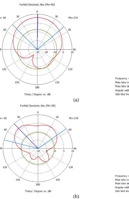
Figures 5 (a) and 5 (b) show that the dual band antenna has a directive gain of 6.1 dBi at 2.4 GHz and 6.3 dBi at 5.2 GHz.
(a)
(b)
Figure 5: Directive gain of the designed antenna (a) at 2.4 GHz (b) at 5.2 GHz
5
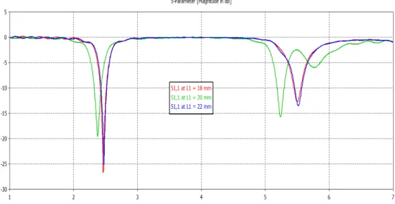
Effects of Varying Slot Dimensions of the Designed Antenna
For proper optimization of the design the antenna slot dimensions were altered within allowed limit as shown in Figure 6. The value of L1 = 20 mm (green colour) produced the best fit for the
120
Figure 6: Variation of slot dimensions for design optimization in CST MWS.
Also, from Figure 7, a radiation efficiency of 86.1 % at 2.4 GHz and 77.4 % at 5.2 GHz are achieved.
Figure 7: Radiation efficiency of the designed dual band antenna
6 Conclusion
The results shown in the various figures show an appreciable level of compliance with the design specifications. With a bandwidth of 115 MHz which represents 5.4 % at 2.4 GHz and 110 MHz representing a BW of 2.3 % at 5.2 GHz, a VSWR of 1.24 at 2.4 GHz and 1.3 at 5.2 GHz and a return loss below -10 dB at both frequency bands on the return loss plot, the designed antenna has met the objectives outlined for the paper.
References
[1] Ren, W. (2008). Compact dual-band slot antenna for 2.4/5 GHz applications. Progress in Electromagnetics Research, 8, 319-327.
121
[3] Tze-Meng, O., Tan, K. G., and Reza, A. W. (2010). A dual-band omni-directional microstrip antenna. Progress in Electromagnetics Research, 106, 363-376.
[4] Jain, K., and Sharma, S. (2013). Dual Band Rectangular Microstrip Antenna for Wireless Communication Systems. International Journal of Innovations in Engineering and Technology (IJIET), 2(4), 235-246.
[5] Asrokin, A., Rahim, M. K. A., and Aziz, M. A. (2005). Dual band microstrip antenna for wireless LAN application. In 2005 Asia-Pacific Conference on Applied Electromagnetics, IEEE, 26-29.
[6] Nag, V.R. and Singh, G. (2012). Design and Analysis of Dual Band Microstrip Patch Antenna with Microstrip Feed Line and Slot for Multiband Application in Wireless Communication. International Journal of Computer Science and Information Technology and Security (IJCSITS). 2(6), 1266-1270.
[7] Subramanian, G. H., & Prabhu, S. S. (2015). Design, analysis and fabrication of 2× 1 rectangular patch antenna for wireless applications. International Journal of Advanced Research in Electronics and Communication Engineering (IJARECE), 4, 599-603.
[8] Mansour, Y. E. (2014). Single slot dual band microstrip antenna for WiMAX application. Atilim University, June.
[9] Vilaltella, R., Hesselbarth, J., & Barba, H. (2014). High-Efficiency Dual-Polarized Patch Antenna Array with Common Waveguide Feed. In Microwave Conference (GeMIC), 2014 German, VDE, 1-3.
[10] Kumar, G. and Ray, K. P. (2003). Broadband microstrip antennas. Artech House.
[11] Balanis, C. A. (2016). Antenna theory: analysis and design. John Wiley & Sons.
[12] Pozar, D. (2012). Microwave Engineering. Wiley.
[13] Stutzman, W. L., & Thiele, G. A. (2012). Antenna theory and design. John Wiley & Sons.
![Figure 3: Return loss of the designed dual band antenna The bandwidth of the antenna is given as [13]:](https://thumb-us.123doks.com/thumbv2/123dok_us/7949685.2112531/5.892.183.731.93.301/figure-return-loss-designed-antenna-bandwidth-antenna-given.webp)