Sharif University of Technology
Scientia IranicaTransactions B: Mechanical Engineering http://scientiairanica.sharif.edu
Brain tissue constitutive material models and the nite
element analysis of blast-induced traumatic brain injury
A. Eslaminejad, M. Hosseini-Farid, M. Ziejewski, and G. Karami
1;Department of Mechanical Engineering, North Dakota State University, Fargo, ND 58108-6050, USA. Received 3 December 2017; received in revised form 16 May 2018; accepted 28 July 2018
KEYWORDS Blast traumatic brain injury;
Finite element modelling; Brain tissue constitutive model; Viscoelastic; Hyperviscoelastic.
Abstract. Traumatic Brain Injury (TBI) often occurs due to assaulting loads such as blast on the human head. Finite Elements (FEs) can approximately simulate blast interactions with the human head. An important parameter in the FE modelling procedures is the accuracy of constitutive formulation of the brain tissue. This paper focuses on implementation of three brain tissue constitutive relations to measure and compare the dynamic behaviour of the brain under identical blast loads. For the geometry, a simple spherical head model is employed to monitor the brain tissue response and examine the uncertainties in FE brain tissue constitutive modelling. The brain tissue is constitutively modelled as hyperelastic, viscoelastic, and hyperviscoelastic material types. Intracranial Pressures (ICP), strains, and shear stresses as the dynamic parameters are measured with time. These biomechanical parameters can be compared against the injury thresholds. Our analyses show that although the results of ICPs and strains are close for the three models, shear stresses are considerably dierent. The study will further provide a new insight into selecting a proper constitutive model of the brain tissue under dynamic conditions.
© 2018 Sharif University of Technology. All rights reserved.
1. Introduction
There are many reported TBI incidents due to high-frequency loads of impact, blast waves, or kinematical motions. Analyzing and understanding the mechanism of TBI will help save many lives across the world. Ex-perimental methods impose moral and technical issues before conducting any research. Many FE studies have been conducted to determine brain responses under dynamic loads to study TBIs [1-10]. Such studies have helped to eciently develop TBI prediction tools based
1. This article is dedicated to Professor Goodarz Ahmadi, my dear teacher and my colleague.
*. Corresponding author. Tel.: +1 701 1231 5859 E-mail address: [email protected] (G. Karami). doi: 10.24200/sci.2018.20888
on the current injury threshold criteria of kinematics, intracranial pressure (ICP), tissue strain, and tissue shear stress [11].
Mechanical responses of human head brain and skull have been studied using multi-material FE simu-lations [5,12]. Representative FE head models, which include major components of the head such as brain, skull bones, and cerebrospinal uid (CSF), have been employed to study the response of the head under dierent loadings. Although FEs have facilitated the biomechanical modeling of the head, they have limita-tions in accuracy of the solution. Such limitalimita-tions come from the complexities of geometries and material prop-erties. The interactions and contact between the head components as well as the uid-solid-type interactions of CSF with the brain and skull fuel the aforementioned complexities. Thus, in general, we should expect approximate solutions by FE modeling in TBI analysis.
constitutive models are implemented.
The intracranial organs and tissues are naturally anisotropic and inhomogeneous. The constitutive mod-els developed for the brain tissue range from linear elastic to nonlinear hyperviscoelastic models. Several experimental studies have shown that the mechanical response of the brain tissue is a function of strain level, strain rate, and load-duration time. Therefore, to predict the biomechanical behavior of the brain, an accurate nonlinear viscoelastic material model of tissue is suggested. Moreover, to consider using such brain tissue constitutive models as utilized in FE simula-tions [13], their accuracies must be validated against the TBI thresholds, too. Although some tolerances of head and brain injuries have been proposed for the impact-induced TBI, it is still a challenging issue for blast-induced TBIs due to the loading complexity and an unknown injury mechanism.
In the head modeling presented here, skull and brain are modeled as solid elements, while CSF is modeled using uid-like solid elements. The skull and CSF are modeled as linear elastic materials. It has been proved the brain presents nonlinear elastic and viscoelastic behavioral patterns [13]. Three widely used tissue constitutive models are, therefore, considered for the brain to perform a comparative blast-induced TBI (bTBI) study: hyperelastic, viscoelastic, and hyper-viscoelastic models [14]. In related literature, each of these material models claims to represent the behavior of the brain in FE simulation of TBI. Therefore, the aim of this study is to analyze and compare the brain tissue responses using these three models.
2. Computational method
2.1. FE discretization and blast FE modeling Three spheres were designed and assembled inside each other to develop a spherical head model. The inner sphere is considered as the brain with a diameter of Dbrain = 18:8 cm, which is in contact with the larger
sphere as CSF with a diameter of DCSF= 23:5 cm. The
outer sphere is considered as the skull with a diameter of Dskull = 27:26 cm, which is exposed to blast
shock-waves. Figure 1(a) and (b) show a schematic of the spherical head model, including the three assembled
spheres and (b) 3D model and FE discretization.
components, and that of the corresponding FE model, respectively.
To simulate the interaction of blast waves with the spherical head model, the Arbitrary-Lagrangian-Eulerian (ALE) method was implemented. The general numerical algorithm for ALE method is as follows: First, solids deform based on Lagrangian formulations; second, the state variables of the deformed Lagrangian elements are mapped back onto the ALE reference mesh over an advection step; eventually, the governing equations in conjunction with solid relationships are solved for state variables. In addition, the FSI among Lagrangian and Eulerian domains is performed based on penalty method. LS-DYNA explicit, transient, and nonlinear FE code was used to simulate blast shockwaves and their eects on solid bodies.
There are two numerical methods utilized to simulate blast in LS-DYNA:
- (i) Lagrangian Methods (Load-Blast-Enhanced or LBE);
- (ii) Multi-Material Arbitrary Eulerian-Lagrangian (MM-ALE) [15].
While the rst one is unable to simulate shock-wave reections at the edges and is of low accuracy, the second approach operates with huge computation cost. Therefore, the coupled method in LS-DYNA provides a combination of these techniques by taking advantage of both methods to reduce the computation cost and increase accuracy. In this technique, blast overpressure was calculated empirically based on the size and location of the explosive and was applied to the ambient, i.e., the surface facing the detonation (Figure 2(a)). Seventy-gram TNT was considered as the detonation and placed approximately at a stand-o distance stand-of 60 cm frstand-om the stand-outer sphere surface. Therefore, the maximum blast overpressure is less than 800 kPa during 0.5 ms. Time history blast overpressure is depicted in Figure 2(b).
For modeling the blast wave, a cubic domain of 50 cm 50 cm 50 cm was constructed and discretized with 6.7 mm brick elements. In addition,
Figure 2. (a) ALE blast domain and the FE spherical model. (b) Time history of blast overpressure.
the elements placed on the side of the air domain cube in x direction were considered as ambient elements (Figure 2(a)). The blast wave overpressure was applied to these ambient elements. The other sides of the air domain cube were considered as non-reecting faces in the media-boundary condition. The ambient air was modeled as the ideal gas to model blast wave pressure. Eq. (1) expresses the state of the model, where p, , , and E are pressure, specic heat ratio = Cp
Cv = 1:4
, air density, and volumetric energy density, respectively.
p = ( 1)
0E: (1)
2.2. Constitutive models
The skull was considered as a linear homogeneous and isotropic elastic material. For CSF, the solid elements with uid properties were used to model it in LS-DYNA. The linear elastic properties of the CSF and skull are presented in Table 1, where is density, E is Young's modulus, v is Poisson Ratio, and K is Bulk modulus.
Several studies have focused on determining the brain tissue constitutive models [16,17]. Linear elastic constitutive models have been used in earlier FE studies in order to simplify the brain constitutive model [14]. However, other research eorts have been made on other brain constitutive models: viscoelastic, hyperelastic, and hyperviscoelastic ones [14,18]. A density of 1.04 g/cm3 was considered for all the brain
tissue constitutive models. The adopted mechanical properties of the brain tissue constitutive models are provided in Table 2 in the following sections.
2.3. Viscoelastic modeling
Several experimental researches have demonstrated that there is a considerable dierence between linear elastic and viscoelastic materials due to loading time, since the brain deformation has viscous modes [14]. Usually, Kelvin viscoelastic model (linear spring and dashpots) is considered for the brain material model. Modeling linear viscoelastic materials in terms of stress-strain relationship need to be done by convolu-tion integrals. Thus, to obtain the stress tensor, the
Table 1. Material properties of CSF and skull. Elastic material
properties
Density,
(g/cm3) Poisson ratio, v
Elastic modulus, E (GPa)
Bulk modulus, K (GPa)
CSF 1.04 0.4887 0.0148 2.19
Skull 1.8 0.21 15 {
Table 2. Mechanical properties of brain tissue constitutive models.
Material models Mechanical properties
Hyperelastic Density (g/cm3) Poisson ratio C10(Pa) C01(Pa)
1.04 0.499994 514.62 566.08
Viscoelastic Density (g/cm3) Bulk modulus (GPa) G0 (kPa) G1 (kPa) (1/sec)
1.04 2.19 43 8 500
Hyperviscoelastic Density (g/cm3) Bulk modulus (GPa) C10(Pa) C01 (Pa) G1 (kPa) G2(kPa) 1 (Hz) 2 (Hz)
Figure 3. Applied strain and the stress relaxation responses with time of tissue material.
convolution integral is written in Eq. (2). It should be noted that the compressible manner of the brain is considered as a linear behavior.
_Sij = 2 t
Z
0
(t )@"ij()
@ d; (2)
where _Sijis the Piola-Kirchho stress rate. In addition,
the shear relaxation modulus () is obtained through Eq. (3):
(t) = G1+ (G0+ G1) e t; (3)
where G1 is the long-term shear modulus, G0 is the
short-term shear modulus, and is the decay factor. These three unknown coecients can be obtained by stress relaxation response with time subjected to strain with constant strain rate. As is presented in Figure 3, the stress-time graph can obtain the unknown coecients of the shear relaxation modulus formula. Viscoelastic material properties used in our study based on cadaveric tests are provided in Table 2 [14]. 2.4. Hyperelastic modeling
Some researchers have considered hyperelastic prop-erties of the brain tissue and introduced them to FE modeling of brain. The strain energy function (Mooney-Rivlin) is modeled as a polynomial function of the principal strain invariant to cope with high-rate elastic deformation as follows:
W = XN
i+j=1
Cij(J1 3)i(J2 3)j; (4)
where J1, J2, and J3can be obtained by:
0 0 z
By considering the rst two terms of the strain energy, the Mooney-Rivlin strain energy function for incom-pressible materials [18] is written as follows:
W = C10(I1 3) + C01(I2 3) ; (7)
where I1and I2are the rst and second principal stress
invariants, respectively. The sum of C10and C01has a
physical meaning as shear modulus 0:
1
20= C10+ C01; (8) where, in this study, 0 is shear modulus about
2160 Pa. As one of the assumptions, the relation between constants is C10
C01 = 0:9. In addition, the bulk
modulus is obtained as 2.19 GPa for the calculated Poisson ratio [18]. The Cauchy Stress is obtained using the principal Kirchho stress components from derivative of strain energy function:
ij = J 1FikSkmFmjT ; (9)
where J, F , and S are Jacobian transformation, de-formation gradient tensor, and Second Piola-Kirchho stress, respectively, which can be obtained by Eq. (10). Based on the experimental data tting, the coecients were estimated to use the Mooney-Rivlin hyperelastic model [18]. Moreover, mechanical property coecients of the hyperelastic constitutive model are provided in Table 2.
Sii= i@W@
i: (10)
2.5. Hyperviscoelastic modeling
The Mooney-Rivlin strain energy function is considered as the third constitutive model studied in this paper. The time decay constant and time-dependent constants of Mooney-Rivlin were derived in terms of time by Mendis et al. [17]. Indeed, viscous dissipative eects were taken into viscous stress, which was related to the elastic stress. Hence, the second Piola-Krichho stress can be obtained by utilizing the convolution integral (Eq. (11)) [1]:
Sij = t
Z
0
Gijkl(t )@E@kld; (11)
relaxation function:
G (t) =Xn
i=1
Gie it;
where 0:5Gi = (C01+ C10). Time-dependent
coe-cients C10 and C01 for Mooney-Rivlin hyperelastic law
are obtained as follows:
C01(t) = AC10(t) = a + be ct + dect: (12)
Hereby, the Cauchy Stress can be written for a hyperviscoelastic model in Eq. (13), in which F is the deformation gradient tensor, J is the transformer Jacobian, and S is the second Piola-Krichho stress.
= J FT S F: (13)
The mechanical property coecient can be ob-tained by utilizing mechanical tests such as tensile and compression tests on brain tissue. Hyperviscoelastic material properties used in our study are provided in Table 2. Hyperviscoelastic constitutive brain tissue model has been used by researchers [19] who have validated their results by experimental tests in terms of ICP responses.
3. Result and discussions
In this study, three material models (hyperelastic, viscoelastic, and hyperviscoelastic) were utilized to model brain tissue under high-frequency blast loading. The blast pressure wave propagation is depicted in Figure 4. At the time when the blast pressure wave reached the outer sphere, the maximum pressure was evaluated as about 780 kPa. In addition, the outer sphere (skull) moves with maximum acceleration about
Figure 5. Skull acceleration of hyperviscoelastic model due to the blast.
80 g (Figure 5). This amount of blast pressure was selected to produce the skull acceleration close enough to the threshold of mild TBI [11].
To quantify the brain injury levels, several cri-teria have been proposed as found in the literature: acceleration, ICP, strain, and stress (mostly shear). Of note, mostly, in engineering application, the failure at a point is measured based on the size of the stress. However, in biomechanics and brain injury studies, for the convenience and following reasons, other failure criteria have been introduced:
Acceleration can be easily measured from experi-ments of the dummy heads (Hybrid III) models;
ICP can be compared with the result of cadaver head models test;
The size of strain involves either in-vitro compres-sion or tencompres-sion tests of brain tissue.
Any of the mentioned criteria used to measure the intracranial brain deformation leads to tissue damage.
Eventually, the size of the shear stress causes ber distortion, shear, rupture, and failure for the brain tissue. FE analysis can eectively measure the size of shear stresses in any type of analysis.
The propagated pressure wave inside the inner sphere (brain) is demonstrated in Figure 6. As seen at t = 1 ms, a small pressure wave starts to propagate inside the skull, CSF, and brain media. As is indicated in Figure 6, there are three regions (regions A, B, and C), in which pressure concentration is considerable. These regions experience considerable pressure in an inner sphere marked as Locations A, B, and C that are located in the front (coup), top site, and backside (contrecoup) regions, respectively. For the three tissue material models, the ICPs were measured and recorded. While hyperviscoelastic and viscoelastic materials predicted a similar maximum ICP peak about 500 kPa in the coup site (Location A), the hyperelastic model predicted an overpressure of 420 kPa. In addition, the behavior of these models was considerably dierent in terms of damping and settling down. The hyperelastic model predicts faster damping than the other two models do.
Another pressure concentration region was de-tected at top of the brain sphere in Location B. In hyperviscoelastic and viscoelastic models, the maxi-mum ICP responses in the top region were close to about 600 kPa and 591 kPa, respectively. However, for the hyperelastic model, the ICP response was 445 kPa. Time histories of ICP variation in Locations A, B, and C are depicted in Figure 7. It can be seen that while hyperviscoelastic and viscoelastic models have very similar Root Mean Square (RMS) values of 136.47 and 136.68, the hyperelastic model has an RMS value of 81.06, which is considerably less than RMS values of the other two models.
As shown in Figure 7, the pressure response in countercoup (Location C) was found signicantly higher than those at other regions with peak rates about 2.02 MPa, 2.04 MPa, and 2.11 MPa for hy-perviscoelastic, viscoelastic, and hyperelastic models, respectively. Although the maximum ICP occurred in the hyperelastic model, the RMS values of the
ICPs in hyperviscoelastic (310.94) and viscoelastic models (313.61) were more than that of hyperelastic model (258.31). The pressure propagation contour is demonstrated in Figure 6 that illustrates the maximum pressure occurring in Location C on the outer surface of the brain and not deep through the brain tissue.
It is observed that at point C on the brain (inner sphere), ICP varied signicantly, which can be due to blast pressure concentration at countercoup. The maximum pressure at point C was approximately four times larger than pressure in Locations A and B. In addition, the considerable negative pressure, about 1:5 MPa, in countercoup (Location C) can anticipate the cavitation phenomenon.
Time histories of the maximum strain response in all Locations A, B, and C are depicted in Figure 8. Unlike the hyperelastic model, the maximum principal strains of the viscoelastic and hyperviscoelastic models in Locations A and B illustrate similar responses under blast. The dynamic response of the models under the blast shockwave showed approximately a similar strain response with RMS values of 0.0165%, 0.0170%, and 0.0166% for hyperviscoelastic, viscoelastic, and hyperelastic models, respectively, in the countercoup location.
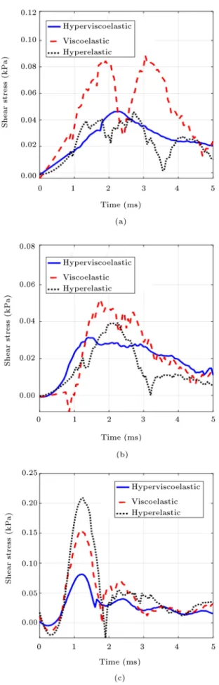
Finally, the maximum shear stress responses to the blast are calculated that show signicant dier-ences, as depicted in Figure 9. The shear stress crite-rion is important because it is the main cause of tissue layer distortion and nervous ber fracture, resulting in diuse injuries. The maximum shear stresses at point A for hyperviscoelastic, viscoelastic, and hyperelastic material models were 0.14 kPa, 0.34 kPa, and 0.20 kPa, respectively. However, in Location C, the hyperelastic material model had the maximum shear stress about 1.37 kPa, which was larger than viscoelastic and hyperviscoelastic models' maximum shear stresses of 1.12 kPa and 0.395 kPa. Since the shear stress in the regions is noisy, the Savitzky-Golay Filter was applied to smooth the measured data.
The maximum shear stress was much larger in the countercoup of the brain sphere in comparison with coup, which was facing blast wave load. The
Figure 7. ICP variation with time at front (a), top (b),
Figure 9. Maximum shear stress in (a) Locations A, (b) Location B, and (c) Location C.
model.
4. Conclusion
Three material models, namely hyperviscoelastic, vis-coelastic, and hyperelastic, were considered as brain tissue models to study the dynamic responses under blast shockwaves. The head model was simplied into a sphere shape to overlook directionality, decrease computation costs, and reduce the complexity of the geometry. Skull, CSF, and brain were considered as three interconnected sphere models.
The tissue dynamic responses were studied in terms of maximum ICP, maximum principal strain, and maximum shear stress. The limitations of these parameters stand as the threshold criteria for TBI. These dynamic values for each of the constitutive models were monitored in the coup and countercoup regions, where their maximum values occur. The countercoup region had the highest ICP, especially on the outer surface of the brain, approximately four times larger than that at the front and top of the spherical brain. The hyperviscoelastic and viscoelastic models had close ICP values; however, for the hyperelastic model, the maximum ICP was lower. The negative pressures, which might claim the cavitation on brain under blast in all cases, occur in the coup and counter-coup regions. Maximum principal strains' changes with time for the viscoelastic and hyperviscoelastic models are similar to ICP's changes with time. Generally, the three constitutive models present a similar response of ICP and strain; specically, the results of the two models (viscoelastic and hyperviscoelastic) were close to each other. The shear stresses of all the models behave dierently and predict dierent responses. Such dierences necessitate regarding the selection of the type of constitutive model as highly important. In addition, as the shear stress is the essential criterion for material failure, it must be considered and compared to the shear stress threshold for TBI.
References
\Biomechan-ical assessment of brain dynamic responses due to blast pressure waves", Annals of Biomedical Engineering, 38(2), pp. 490-504 (2010).
2. Cotton, R., Pearce, C.W., Young, P.G., Kota, N., Leung, A., Bagchi, A., and Qidwai, S. \Development of a geometrically accurate and adaptable nite ele-ment head model for impact simulation: the Naval research laboratory-impleware head model", Computer Methods in Biomechanics and Biomedical Engineering, 19(1), pp. 101-113 (2016).
3. Eslaminejad, A., Sarvghad-Moghaddam, H., Rezaei, A., Ziejewski, M., and Karami, G. \Comparison of brain tissue material nite element models based on threshold for traumatic brain injury", ASME 2016 International Mechanical Engineering Congress and Exposition, Phoenix, AZ, USA: American Society of Mechanical Engineers (2016).
4. Sarvghad-Moghaddam, H., Rezaei, A., Eslaminejad, A., Ziejewski, M., and Karami, G. \Mechanical response of the brain under blast: The eect of blast direction and the head protection", ASME 2016 International Mechanical Engineering Congress and Exposition. Phoenix, AZ, USA: American Society of Mechanical Engineers (2016).
5. Sarvghad-Moghaddam, H., Rezaei, A., Ziejewski, M., and Karami, G. \Evaluation of brain tissue responses due to the underwash overpressure of helmet and faceshield under blast loading", International Journal for Numerical Methods in Biomedical Engineering, 33(1), Electrical article: E02782 (2016).
6. Grujicic, M., Bell, W.C., Pandurangan, B., and He, T. \Blast-wave impact-mitigation capability of polyurea when used as helmet suspension-pad material", Mate-rials & Design, 31(9), pp. 4050-4065 (2010).
7. Moore, D.F., Jerusalem, A., Nyein, M., Noels, L., Jaee, M.S., and Radovitzky, R.A. \Computational biology-modeling of primary blast eects on the cen-tral nervous system", Neuroimage, 47, pp. T10-T20 (2009).
8. Nyein, M.K., Jason, A.M., Yu, L., Pita, C.M., Joannopoulos, J.D., Moore, D.F., and Radovitzky, R.A. \In silico investigation of intracranial blast mit-igation with relevance to military traumatic brain in-jury", Proceedings of the National Academy of Sciences (2010).
9. Sarvghad-Moghaddam, H., Rezaei, A., Ziejewski, M., and Karami, G. \A comparative study on the pro-tection eciency of combat helmets against ballis-tic impacts and blast waves", in Journal of Head Trauma Rehabiliation, 12th Annual Conference on Brain Injury, North American Brain Injury Society, San Antonio, Texas, April 29-May 2, pp. E66-E66 (2015).
10. Sarvghad-Moghaddam, H., Karami, G., and Ziejew-ski, M. \The eects of directionality of blunt
im-pacts on mechanical response of the brain", ASME International Mechanical Engineering Congress and Exposition, Montreal, Canada: American Society of Mechanical Engineers (2014).
11. Zhang, L., Yang, K.H., and King, A.I. \A proposed injury threshold for mild traumatic brain injury", Journal of Biomechanical Engineering, 126(2), pp. 226-236 (2004).
12. Sarvghad-Moghaddam, H., Jazi, M.S., Rezaei, A., Karami, G., and Ziejewski, M. \Examination of the protective roles of helmet/faceshield and directional-ity for human head under blast waves", Computer Methods in Biomechanics and Biomedical Engineering, 18(16), pp. 1846-1855 (2015).
13. Hoseini-Farid, M., Eslaminejad, A., Ziejewski, M., and Karami, G. \A study on the eects of strain rates on characteristics of brain tissue", ASME Interna-tional Mechanical Engineering Congress and Exposi-tion, Tampa, FL, USA: American Society of Mechani-cal Engineers (2017).
14. Tse, K.M., Lim, S.P., Tan, V.B.C., and Lee, H.P. \A review of head injury and nite element head models", American Journal of Engineering, Technology and Society, 1(5), pp. 28-52 (2015).
15. \LS-DYNA, LS-DYNA keyword user manual", Version 971, Livermore Software Technology Corporation: Liv-ermore, California (2007)
16. Miller, K. and Chinzei, K. \Constitutive modelling of brain tissue: experiment and theory", Journal of Biomechanics, 30(11), pp. 1115-1121 (1997).
17. Mendis, K., Stalnaker, R., and Advani, S. \A consti-tutive relationship for large deformation nite element modeling of brain tissue", Journal of Biomechanical Engineering, 117(3), pp. 279-285 (1995).
18. Cha, M.S., Ganpule, S., Gu, L., and Chandra, N. \Dynamic response of brain subjected to blast loadings: inuence of frequency ranges", International Journal of Applied Mechanics, 3(04) pp. 803-823 (2011).
19. Sarvghad-Moghaddam, H. \Computational biome-chanics of blast-induced traumatic brain injury", Role of Loading Directionality, Head Protection, and Blast Flow Mechanics, North Dakota State University, Ph.D. Thesis (2015).
Biographies
Ashkan Eslaminejad is a PhD Candidate in Me-chanical Engineering program at North Dakota State University (NDSU). He received Master of Engineering in Mechanical Engineering from University of Malaysia in Kuala Lumpur, Malaysia. He joined the Compu-tational Biomechanics Lab at NDSU in Fall 2015. His research areas of interest include experimental and the-oretical vibration analysis, computational mechanics of uid-structure interaction systems, and biomechanics
Mariusz Ziejewski is a Professor at the Depart-ment of Mechanical Engineering at the North Dakota State University. He received his PhD in Mechan-ical Engineering in 1986 from North Dakota State
don, England. Dr. Karami's research interests include multi-scale computational biomechanics, tissue engi-neering, constitutive modeling, composite engiengi-neering, and engineering design.