Installation and Programming Manual
(Ver 4.31 and above)
Chapter 1: Introducing WisDom...1-1 What is the WisDom? ...1-1 WisDom Architecture and Capabilities ...1-2 WisDom Features ...1-3 Technical Specifications ...1-4 Chapter 2: Installing the WisDom ...2-1
WisDom Installation Steps...2-1 WisDom Components...2-2 Mounting the WisDom ...2-3
Choosing the mounting location...2-3 Wall Mounting the WisDom...2-3
Wiring the WisDom...2-6
Connecting AC Power ...2-6 Connecting the Telephones Lines...2-6 Wiring the Bell Tamper ...2-7 Wiring the Programming Outputs...2-7 Wiring an External Sounder ...2-7 Ground Connection...2-8 Wiring the Hardwire Zone ...2-9 Connecting the Backup Battery ...2-9 Auxiliary Terminal ...2-10 Wired Expansion Bus Modules (Optional)...2-10 Jumpers Setting...2-11 Adjusting the LCD Contrast ...2-12 Chapter 3: Programming the WisDom...3-1
WisDom Programming Options...3-1 Using the WisDom’s LEDs and Keys ...3-2 Engineer Programming from the WisDom Keys ...3-3
Accessing the Engineer Programming Menu ...3-4 Restoring Manufacturer's Programming Defaults...3-5 Keypad Timeout...3-6
Using the Program Transfer Module (PTM) ...3-7 Chapter 4: Using the Engineer Programming Menus...4-1
Engineer Programming Menu Conventions ...4-1 System...4-2 System: Timers...4-2 System: Parameters ...4-4 System: Receiver...4-13 System: Clock...4-15 System: Labels ...4-16
System: Version ...4-20 Zones……...4-21 Zones: Allocation ...4-21 Zones: Parameters ...4-22 Zones: Testing...4-31 Zones: Editing...4-33 Zones: Crossing ...4-34 Zones: Alarm Confirmation ...4-35
Programmable Outputs...4-37
Programmable Outputs: Define ...4-37 Programmable Outputs: Output A...4-44 Programmable Outputs: Output B...4-44
Code Maintenance...4-45
Codes: Authority ...4-46 Codes: Partition ...4-47 Codes: Grand Master ...4-48 Codes: Engineer...4-48 Codes: Sub-Engineer ...4-49 Codes: Code Length...4-50
Digicom ...4-51
Digicom: ARC Link - Up...4-51 Digicom: Customer Account Numbers...4-53 Digicom: ARC Communication Format ...4-54 Digicom: U/D Telephone Number ...4-56 Digicom: U/D Access and ID ...4-56 Digicom: Controls ...4-57 Digicom: Parameters ...4-60 Digicom: ARC Report Split ...4-65 Digicom: Follow-Me ...4-67
Report Codes ...4-71
Report Codes: Auto Codes...4-71 Report Codes: Manual Codes ...4-73 Alarm Receiving Station: Voice Alarm Verification...4-82
Key-fobs ...4-83
Key-fobs: Allocation...4-83 Key-fob: Parameters...4-84 Key-fob: Communication Test...4-85
Keypads ...4-86
Exit Programming...4-99 Chapter 5: Engineer Programming Within the User Programming Menu ...5-1
User Authorization for Engineer Programming...5-1 Programming the Voice Messages...5-1
Voice Messages Types...5-2 Message Structure...5-3 Voice Message Labels...5-3 Test Message ...5-7 Local Announcement Messages...5-8
Walk Test...5-9 Replacing Backup Batteries ...5-9 Appendix A: Report Codes...A-1
Report Code Programming for SESCOA SUPERFAST (03B1) ...A-1 Report Code Programming for ADEMCO POINT (CONTACT) ID (0420) ...A-2 Report Code Programming for SIA (0700) ...A-3 Appendix B: Event Log Messages...B-1 Appendix C: EN50131 Default Values...C-1 Appendix D: WisDom Accessories...D-1
This chapter provides a basic introduction to the WisDom system, its architecture and capabilities, as described in the following sections:
♦ What is the WisDom? below
♦ WisDom Architecture and Capabilities, page 1-2
♦ WisDom Features, page 1-3
♦ Technical Specifications, page 1-3
What is the WisDom?
The WisDom is a fully featured wireless security system, providing sophisticated solutions for alerting and reporting premises alarm signals.
The WisDom has been specifically designed to meet a wide range of security needs of homes, offices and small commercial applications.
The WisDom is simple and fast to install. It has a user friendly interface that enables easy installation, programming and use. In addition, the WisDom can also be programmed and/or controlled through local or remote Upload/Download software installed on a PC computer with a Windows operating system.
It has a built in sounder and it is designed around microprocessor and EEPROM (Electrically Erasable Programmable Read-Only Memory) technology, which stores the system's operating program, as well as its programmable parameters, without dependency on external power sources.
The WisDom is available in 868.65 MHz Radio Frequency. The WisDom main benefits are:
¾
Engineer Benefits:♦ Simple programming logic – fully menu driven
♦ Wireless calibration and adjustable threshold level, enables higher false alarm immunity.
♦ Actual transmitter signal strength and RF noise displayed on LCD, eliminating the need for an external strength meter.
♦ All detectors supervised for presence, low battery, jamming and tamper
♦ Supports all major central station reporting codes.
¾
User Benefits:♦ Full voice guide enables simple remote phone operation
♦ Built in two-way voice communication to the premises.
♦ Local announcement and feedback of system status.
♦ Family message center.
♦ Dedicated buttons for simple emergency notification
♦ Quick key operation of users functions
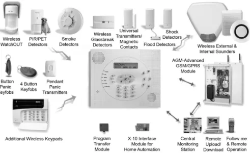
The following diagram provides an overview of the WisDom's architecture and capabilities. Examine this figure before beginning your WisDom installation to obtain an overall picture of the full extent of the WisDom system's capabilities.
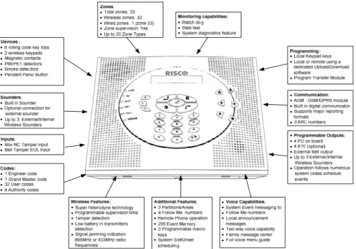
The following illustration describes the main features of the WisDom.
The following technical specifications are applicable for the WisDom: Electrical Characteristics
System Power 230/120VAC, External Transformer 1500mA, 9VAC
Current Consumption (Standby / Maximum)
140 mA minimum / 1200 mA maximum
Backup Battery 6 x 1.5VDC Size AA, Alkaline
or
6 x 1.2V Size AA, rechargeable cells
Relay Outputs 2 x 3 Amps 24 VDC programmable relay outputs
Transistor Outputs 2 x 70mA transistors (Open Collector)
Auxiliary Power 9V DC @ 200 mA maximum
Bell/LS(External) Sounder Output
9V DC @ 500mA maximum
Internal Bell intensity 90 dbA / 1 m
Operating Temperature -10°C to 40°C (14°F to 104°F)
Physical Characteristics
Dimension 24 cm x 19 cm x 4.8 cm (9.4 in x 7.4in x 1.8in)
Weight (with batteries) 0.970 Kg
Wireless Characteristics
RF immunity According to EN50130-4
This chapter covers the installation procedures of the WisDom, as follows:
♦ WisDom Installation Steps, below
♦ WisDom Components, page, 2-2
♦ Mounting the WisDom, page 2-2
♦ Wiring the WisDom, page 2-6
WisDom Installation Steps
The following workflow illustrates the recommended method for installing the WisDom. A detailed description of each step is provided in the following sections of this manual.
1. Create an installation Plan
See Chapter 2
Choose a mounting location near AC outlet telephone outlet and easy to operate.
2. Wire the WisDom See Chapter 2
Connect AC power, telephone line, outputs, external sounder, ground connection, wired zone and batteries.
3. Power Up and Defaulting See Chapter 3 page 3-5 and Chapter 4 page 4-17
Set the default jumper on both pins and power up the system.
4. Enter Engineer Menu See Chapter 3 page 3-3
To programming menu, from the user menu press:[*][9][Engineer code][#].
5. Calibrate the Receiver See Chapter 4 page 4-13
To calibrate the receiver press: [1][3][1][#] from the main Engineer menu.
6. Allocate and Mount the Wireless Devices
See Chapter 4 page 4-19 for zones, page 4-80 for Key-fobs, page 4-83 for Keypads, page 4-85 for More Devices (GSM, Wireless Sirens and X-10 modules).
Use the supplied devices instructions.
7. Perform Comm. Test See Chapter 4 page 4-19 for zones, page 4-80 for Key-fobs, page 4-83 for keypads, page 4-85 for More Devices (GSM, Wireless Sirens and X-10 modules).
Perform a communication test for each device as described in this manual.
8. Set Receiver Times See Chapter 4 page 4-14
Define jamming and supervision times in quick key programming location: [#][1][3][2] / [3].
9. Complete Programming See Chapter 4
Complete all programming parameters (zones, Digicom, programmable outputs etc.)
10. Exit Programming
See Chapter 4 page 4-95
After exiting the installer programming menu perform a Walk test [*][4][code][2] and check communication with the ARC.
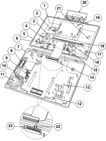
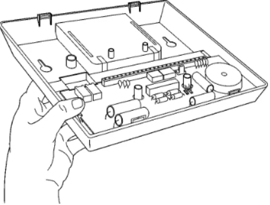
The illustration below shows the internal components when the front panel is separated from the back plate.
J500
Figure 2-1: WisDom Internal components Layout
1. Back panel 9. Tamper spring 17. Internal sounder / buzzer
2. Tamper housing 10. Default jumper (J9) 18. Main terminal block
3. Wires access hole 11. Speaker 19. Battery locking screw
4. Telephone connectors 12. AC restore jumper (J6) 20. Backup battery holder
Choosing the mounting location
Before you mount the WisDom, study the premises carefully in order to choose the exact location of the unit for the best possible coverage and yet easily accessible to prospective users of the alarm system.
The mounting place of the WisDom should be:
♦ Try to centrally locate the system, as close as possible to the transmitters.
♦ Near an uninterrupted AC outlet.
♦ Near a telephone outlet.
♦ Far from sources of interference, including: Direct sunlight or heat sources
Electrical noise such as computers, televisions etc. Large metal objects, which may shield the antenna.
♦ In a place where the alarm can be heard during Part setting mode.
Wall Mounting the WisDom
The WisDom is comprised of two sub-assemblies (front panel and back panel). It is mounted on the wall, using the proper hardware, as described below.
¾
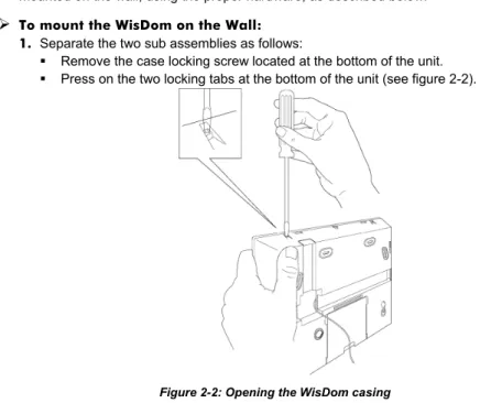
To mount the WisDom on the Wall: 1. Separate the two sub assemblies as follows: Remove the case locking screw located at the bottom of the unit. Press on the two locking tabs at the bottom of the unit (see figure 2-2).
Figure 2-2: Opening the WisDom casing
Gently hold the front panel from both sides, pull it up to a 45° angle and slide it to front to release the front panel from the two locking tabs at the top of the unit, see figure 2-2. (DO not open the front cover to a larger angle in order not
4. Release the back panel holding tabs (see Figure 2-3) located on both sides of the PCB and pull out the PCB gently.
Figure 2-3: Releasing the PCB
5. Hold the back panel against the wall as a template and mark the locations for the mounting holes (6 mounting holes are available).
6. Drill the desired mounting holes and place the screw anchors. When attaching the box to the wall, it is recommended to use 4.2mm, 32mm length screws (DIN 7981 4.2X32 ZP)
7. Open the wire entry knockouts in the back panel and insert the wires and cables via the cable’s opening (including AC cable and telephone cable), see figure 2-4.
Figure 2-4: Open cable knockouts
8. Adjust the Tamper switch (using a flat screwdriver) according to your preferred configuration.
11.If desired, before closing the unit:
Set the jumpers as described on page 2-11. Set the LCD contrast as described on page 2-12.
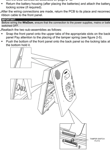
Return the battery housing (after placing the batteries) and attach the battery locking screw (if required).
12.After the wiring connections are made, return the PCB to its place and reconnect the ribbon cable to the front panel.
! IMPORTANT:
Before wiring the WisDom, ensure that the connection to the power supplies, mains or battery, is switched OFF.
13.Reattach the two sub-assemblies as follows:
Snap the front panel onto the upper tabs of the appropriate slots on the back panel Pay attention to the placing of the tamper spring (see figure 2-5). Push the bottom of the front panel onto the back panel so the locking tabs at
the bottom hold it.
Figure 2-5: Locking tabs and Tamper Spring
Reattach the case locking screw located at the bottom. On closing, a click should be heard.
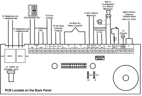
This step explains the various wiring and connection procedures that must be performed when wiring the WisDom, as follows
! IMPORTANT:
Before wiring the WisDom, ensure that the connection to the power supplies, mains or battery, is switched OFF.
Figure 2-6: WisDom Wiring Diagram
Connecting AC Power
The WisDom is powered by a safety approved 230V/120VAC to 9VAC 1500 mA transformer (supplied, RISCO Group part number 1ACA230V9VUK for 230V VAC to 9VAC).
1. Connect the transformer to an AC source and to the AC connector (optional) or the AC terminals.
NOTES:
Do not connect the transformer to a power supply until you have completed all your wiring. If you remove power from the unit (AC and battery), wait at least 10 seconds before reapplying power.
Connecting the Telephones Lines
Connect the system to a telephone line if the system is monitored or a remote connection to a follow me number is required.
Connect the bell tamper to the BELL TMP and COM terminals on the PCB’s block terminals using a 2.2 KΩ
resistor. NOTE:
Bell tamper will be indicated only if the system parameter External Bell, (quick key [1][2][31]) is defined as Yes. For more information refer to page 4-10.
BELL TAMPER
2.2
K EOL RESISTORWiring the Programming Outputs
The WisDom includes 4 programming outputs (2 x 24VDC 3Amps relays, 2 x 13.8 VDC 70 mA transistor outputs). These outputs help operate external devices in response to a number of system activities related to alarms, zones, partitions, general system events, actions of particular user or scheduled events based on the system’s internal clock.
¾
To wire Relay Outputs (PO1- PO2)The connections of relay outputs PO1 and PO2 depend on the settings of jumpers J5 and J4 consecutively, which determine the outputs behavior. Wire the devices that you want to activate to the outputs PO1-PO2, as follows:
NOTE:
The maximum current for PO1 and PO2 should not exceed 200 mA in POS or NEG configurations. In 1 PIN Only configuration with an external power supply the maximum current for PO1 or PO2 should not exceed 3 Amps.
COM UO2 / UO1 N.O C N.C + -J4 (UO2) or J5 (UO1) POS PO2 / PO1 J4 (PO2) or J5 (PO1)
Positive: The C terminal on PO1/PO2 receives 9 VDC AUX UO2 / UO1 N.O C N.C + -J4 (UO2) or J5 (UO1) NEG
Negative: The C terminal on PO1/PO2 receives COM EXTERNAL POWER UO2 / UO1 N.O C N.C + -J4 (UO2) or J5 (UO1) 1 PIN Only J4 (PO2) or J5 (PO1) PO2 / PO1
1 PIN only: PO1/PO2 behave as dry contacts
¾
To wire Transistor Outputs (PO3-PO4)Connect the positive connection of the device to AUX (+) and the negative connection to the PO's (-) terminals.
Wiring an External Sounder
The WisDom is equipped with a built-in sounder (see figure 2-1). If desired, an external bell or piezo sounder can be connected to alert occupants and neighbors with a loud sounder during an alarm.
¾
To wire an external sounder1. Connect the external sounder wires to the BELL (+) (-) terminals. Ensure that you note the polarity when connecting an electronic sounder and/or polarized bells.
For a bell or electric sounder the WisDom produces a steady 9VDC voltage or a slow pulsating voltage, depending on the alarm type. Use a 9V 500mA maximum rated bell sounder.
! WARNING:
To avoid Bell Loop Fault if NO connection is made to the BELL terminals, connect a 2200Ω resistor between the terminals.
NOTES:
It is important to define the BELL/LS system control parameter correctly. The definition varies depending on the type of sounder.
If the bell output is overloaded (exceeds 500 mA) and is shut down, you must disconnect the load from the output for a period of at least 10 seconds before you reconnect any load to the auxiliary output
Ground Connection
Grounding provides a degree of protection against lightning and induced transients for any piece of electronic equipment that may, due to lightning or static discharge, experience permanent or general malfunctions. The ideal ground is considered to be a unified earth
ground in which an 8-foot copper-clad rod, located close to the existing power and telephone
ground rods, is sunk several feet into the earth. Appropriate hardware and clamps are then used to electrically connect each of these rods together and then to the ground terminal of the device to be protected.
It may be possible to use an existing electrical ground on the premises if one is close enough to the WisDom. When connecting the ground wire, use a solid 14-gauge wire [or larger (numerically lower) size]. Keep this wire as short as possible and do not run it in conduit, coil it, bend it sharply, or run it alongside other wiring. If you must bend it or change its direction, it should have a radius of at least 8 inches at the point from which it is bent. If in doubt, you may want to enlist the help of a licensed electrician in matters concerning such grounding.
¾
To connect to ground (Earth)Connect between the WisDom’s ground terminal and an acceptable electrical ground connection for the lightning transient protective devices in this product to be effective.
! IMPORTANT:
The WisDom supports 1 hardwire zone - Zone 33 which can be used for example to connect a key switch. Connect this zone using twisted–pair or 4-conductor cable wiring.
The following diagram illustrates the various zone connections: NOTE:
The hardwire zone cannot be used as a fire zone.
For a zone with a tamper switch, you can use a Double End-of-Line Resistor to save additional connections.
END OF LINE ZONE (N.O CONTACT) zone com
ALARM
2.2 K
DETECTOR NORMALLY OPEN ZONE
CONFIGURATION ALARM zone com DETECTOR NORMALLY CLOSED ZONE CONFIGURATION ALARM zone com DETECTOR
END OF LINE ZONE (N.C CONTACT) 2. 2 K zone com ALARM DETECTOR
DOUBLE END OF LINE ZONE CONFIGURATION com 2.2 K ALARM TAMPER zone 2.2 K DETECTOR
Connecting the Backup Battery
The WisDom has 6 backup batteries that are used in time of main power failure. The batteries can be of two types:
♦ Rechargeable: Size AA, 1.2VDC cells
♦ Non rechargeable: Size AA, 1.5VDC Alkaline
! IMPORTANT:
The provided batteries by the manufacturer are rechargeable Nickel Metal size AA 1.2V 2300mA.
! CAUTION:
If rechargeable batteries are to be used, verify that J10 jumper is positioned on its two pins (see page 2-11) Failure to comply with the above instruction, may result in damage to personnel or equipment.
¾
To insert the Backup batteries:1. Pull the WisDom battery housing outward.
2. Place the 6 batteries inside the battery housing. Pay attention to the batteries polarity printed on the case.
3. Insert the battery housing back to its place.
4. Secure the battery housing with the locking screw (if required).
5. After all wiring is done plug the transformer into the wall outlet.
6. To test the new batteries perform Battery Voltage test (User menu: Quick key [4][1][6]) and only then the regular Battery Test (User menu: Quick key [4][1][5]).
NOTE:
Rechargeable batteries should be charged for at least 24 hours. The “low battery” fault should disappear within 15 minutes after the battery is charged.
IMPORTANT:
1. When replacing the batteries be sure to buy the same type (Nickel Metal up to 2500mA). Failure to comply with this instruction may result in damage to personnel and/or equipment.
2. CAUTION: Replacing a rechargeable cell with a non-rechargeable battery might cause damage unless you change the RECHARGABLE BATTERY jumper, located inside the WisDom.
Use the Auxiliary Power AUX (+) COM (-) terminals to power devices that require a 9VDC power supply with maximum current consumption of 200mA.
NOTES:
The total power from the AUX terminals should not exceed 200mA.
If the auxiliary output is overloaded (exceed 200mA) and is shut down, you must disconnect the load from the output for a period of at least 10 seconds before you reconnect any load to the auxiliary output.
Wired Expansion Bus Modules (Optional)
The WisDom includes provision for wiring of optional expansion modules. This refers to the set of 4 terminals located on the terminal block marked as AUX RED, COM BLK, BUS YEL and BUS GRN. For example, to connect the X-10 interface module you should use the BUS terminals. The connections for the expansion modules are terminal to terminal with color-coded wires as follows:
BUS Terminal Description
AUX RED +9V power for BUS expansion modules
COM BLK Black 0V common for BUS expansion modules
BUS YEL Yellow DATA connection for BUS expansion modules
BUS GRN Green DATA connection for BUS expansion modules
NOTE:
To prevent a possible drop down in voltage use a quality 4-conductor cable with an appropriate gauge size. The maximum wire run permitted is 300 meters (1000 feet) for all legs of the BUS.
The WisDom is equipped with internal jumpers. Use the following table to configure the jumpers according to the desired configuration:
Jumpers on
front panel Position Function
Enables to default the panel and restore the WisDom to the manufacturers default settings.
Position the jumper plug over both pins when reinstating factory installed defaults values to the Main Panel programming (refer to Chapter 3, Programming the WisDom) or for installing
programming using the Program Transfer module.
DEFAULT (J9)
(Default)
Maintains the last programming setting and disables the restoring of the WisDom to the manufacturers default settings.
Position the default jumper plug over one pin for safekeeping. Enables continuous battery charging. Use this setting when using
rechargeable batteries.
RECHARGEABLE BATTERY (J10)
(Default)
Disables battery charging. Use this setting when using non-rechargeable batteries.
Battery Discharge Protection is ON: If a continuous AC power outage occurs, the WisDom automatically disconnects the battery when its backup battery voltage drops below 6.3 VDC, in order to prevent "deep discharge” that may damage the battery.
NOTE:
In this position, the WisDom will not start to operate from a battery power supply, unless connected to the Mains first.
AC RESTORE (J6)
(Default)
Battery Discharge Protection is OFF; The battery may be totally discharged during continuous AC failure, thus battery
replacement may be required (no deep discharge protection). NOTE:
In this position, the WisDom will start to operate from a battery power supply whether it is connected to the Mains or not.
(Default)
Tamper of the case locking screw is disabled (default) when the jumper plug is positioned over two pins.
TAMPER JUMPER (J500)
To enable Tamper protection, remove the jumper plug. Jumpers on
back panel Position Function
UO1 (J5) or UO2 (J4)
Determines the PO1 / PO2 connection (behavior), see “Wiring the Programming Output” section on page 2-7.
The WisDom includes a trimmer located on the PCB of the front panel, next to the default jumper (see figure 2-1) that enables you to adjust the brightness and contrast of the LCD display. It is recommended to adjust the LCD display after powering up the system but prior to reattaching the two sub-assemblies when closing the unit.
¾
To adjust the LCD contrast:Using a Philips screwdriver turn the trimmer clock-wise or counter clock-wise until the desired intensity is achieved
Chapter 3: Programming the WisDom
The WisDom is designed around microprocessor and EEPROM (Electrical Erasable Programming Read Only Memory), which stores the system’s operating program, as well as its programmable parameters, without dependency of external power sources.This chapter explains the WisDom programming options, how to use the keypad elements, and the basics about programming via the keys. You can program the system at any time, even before installing it. All you need is to apply temporary power to the unit.
For detailed information about each Programming option, refer to Chapter 4, Using the
Engineer Programming Menus.
WisDom Programming Options
The WisDom can be programmed locally or remotely. The following describes the options to program the WisDom:
♦ Local operation using the numerical Keys and LCD Display: Instructions are provided on page 3-3.
♦ Program Transfer Module (PTM): (p/n RP128EE0000A) The PTM is a tiny circuit board into which a copy of the WisDom's configuration can be copied and stored as well as transferred to any installation when temporarily plugged into the 4-wire BUS connector. For detailed instructions refer to page 3-7 .
♦ Upload/Download (U/D): A software application that enables you to program the WisDom from a PC computer. It offers the following two alternatives:
Working locally, through a portable computer connected to the WisDom Working at a remote site, communicating with the WisDom via a phone
line and modem
When using the Upload/Download software, the following is required: IBM compatible PC
Upload/Download software
BUS adapter (p/n RP296EBA000A) cable and plug to connect between the PC serial COM port and the WisDom J1 BUS connector (for on-site use)
Modem with access to a phone line (for remote use).
USB/485 converter for on-site use (p/n RP128EUSB00A) to connect between a PC USB port and the WisDom J1 serial connection. For additional details, refer to a RISCO Group technical support representative.
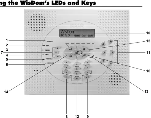
Using the WisDom’s LEDs and Keys
1 2 3 4 5 6 7 12 14 8 9 11 10 15 13 16Figure3-1: The WisDom Surface
The WisDom surface contains six LED indicators, an LCD display and a variety of keys. The LEDs have a different indication during programming mode than in normal operation mode. The LED’s indication in normal operation mode is described in the WisDom user manual. The following table describes the LEDs and keys typical uses during the programming mode:
Item Key/LED Programming Mode
1 Power LED Slow flashing LED = an active programming session 2 Set LED 3 Ready LED 4 Omit LED 5 Fault LED 6 Message LED
These LEDS are off (unlit) during programming operations.
7 These keys do not function during programming operations
Item Key/LED Programming Mode
10 LCD Program
Display The LCD program display consists of two lines. The top line displays information about the main selection mode, and the bottom line displays information and/or data about the specific option set. Such data may be changed through keypad entry. When programming, up to 16-characters can be entered into a line, as required.
11
These keys do not function during programming operations
12 0 through 9 Use the numbered keys, 0 through 9, to key in numbers and/or special characters when labeling zones, areas, and partitions. (For information about how to use the keypad for labeling zones, areas, and partitions, refer to Chapter 4, Using the
Engineer Programming Menus.)
13 Press either one of these keys to move back and forth through the programming level functions.
These keys also change the position of the flashing cursor. When editing a selection, the cursor moves to the left or right respectively.
14 Use this key to toggle forward through the programming choices within a selection.
15 Use this key to toggle backward through the programming choices within a selection.
16 This key does not function during programming operations
Engineer Programming from the WisDom Keys
This section explains how to use the WisDom keys to access the Engineer Programming menu as well as how to restore the manufacturer's defaults, as described in the following sections:♦ Accessing the Engineer Programming Menu, below ♦ Restoring Manufacturer's Programming Defaults, page 3-5 ♦ Keypad Timeout, page 3-6
Accessing the Engineer Programming Menu
This section describes how to access the Engineer Programming menu after the WisDom has been defaulted, as well as how to access it from the regular operation mode.
¾
To access the Engineer Programming Menu:1. When you power up the system for the first time, the display of the regular operation mode will be:
WisDom: --:-- ... .. ... WisDom: --:-- ... .. ...
2. From the regular operation mode press . The display will be:
The display prompts you for authorization code (Grand master, Master or the Manager code). Enter code [1][2][3][4] (default for Grand Master), followed by
.
3. After pressing the keypad displays the first User Functions option, as follows: User functions:
1)Omit zone Ð
User functions: 1)Omit zone Ð
Press [9] to select the Engineer option or use the key. The keypad displays the first option, as follows:
Engineer:
1)Full prog. Ð
Engineer:
1)Full prog. Ð
4. Press [1] Full prog. to enter the full programming menu. The display prompts you for the Engineer code, as follows:
GM/MST/MGR code: _
GM/MST/MGR code: _
5. Enter the authorization code (Grand master, Master or the Manager code) followed by . The following message display appears.
Engineer code:
Engineer code:
NOTES:
1. The authorization code is defined by default as Enable. For more information refer to Chapter 4, Quick key [1][2][41].
2. After the Engineer exits the programming menu, the engineer can access the Engineer programming for one hour without the authorization code.
6. Enter the default Engineer Code: [0][1][3][3]
The code appears as ΘΘΘΘ on the LCD display, as follows: Engineer code:
7. Press The following message display appears: Installation:
Please wait, Installation: Please wait,
Followed by the following message:
8. Press to erase Wireless transmitters. The following message display appears:
Choose YES (Y) or NO (N) using the key, to erase Or
Use the key to abort and access the first main Engineer Programming menu option is displayed bellow:
Engineer Prog: 1)System Engineer Prog: 1)System
The Power LED begins flashing slowly at this point, indicating that you have entered a programming session.
The main Engineer Programming menu options are available, as follows:
[1] System [6] Report codes
[2] Zones [7] Key Fobs
[3] Programmable Outputs [8] Keypads
[4] Codes [9] More Devices
[5] Digicom [0] Exit Programming
Each of the main Engineer Programming menu options enables you to access and program all of the WisDom options. Each option is also discussed in detail in Chapter 4,
Using the Engineer Programming Menus.
Restoring Manufacturer's Programming Defaults
You may find it useful to be able to remove all changes made to the WisDom’s programming and restore the default settings provided by the manufacturer.
! IMPORTANT:
Before defaulting the WisDom you should enable the Default Enable/Disable parameter that controls the authority to restore to the manufacture’s defaults. The Default option for this parameter, as defined by the manufacturer is
Enable. The quick programming key for this parameter is [1][7] from the main Engineer-programming menu.
If you need to program this parameter, remember to exit the Engineer-programming menu, after you set your choice, and save your selection.
¾
To restore the WisDom to the manufacturer's defaults:1. Make sure that the Default Enable/Disable parameter is set to Enable (The default as supplied by the manufacturer is Enable)
4. Reconnect the power to the WisDom. All the LEDs flash once and a long beep is heard. The following message is displayed:
WisDom: --:-- ... .. ... WisDom: --:-- ... .. ...
NOTE:
The Omit LED is ON as long as the default jumper (J9) is on both pins .
5. Reposition the J9 default jumper on one of the J9 pins (where it resides for safekeeping).
6. Access the Engineer-programming menu as described on page 3-4 and program the system, as required.
NOTE:
Remember that the Engineer Code has been restored to the manufacturer's default [0][1][3][3].
7. When you finish your programming, exit the Engineer-programming menu by selecting [0] Exit from the main Engineer-programming menu. The display prompts you to save your changes by displaying the following message:
Do you want to save the data? Y Do you want to save the data? Y
8. Confirm saving the data by pressing the key. A short beep is heard and the following messages are displayed.
Please wait Data saving… Please wait Data saving…
9. When the function is completed, the display goes to regular operation mode, as follows: WisDom:
--:-- ... .. ... WisDom: --:-- ... .. ...
If while exiting, the following display appears, this means that the J9 default jumper is NOT positioned on 1 pin, but wrongly positioned on both J9 pins.
Keypad Timeout
If, after 15 minutes, during the Engineer programming, no entry is made to the keys the WisDom will produce an audible reminder, consisting of several beeps in rapid succession, along with the following display:
Timeout Hit any key
Timeout Hit any key
Pressing any key stops the beeping. To re-enter the Engineer Programming menu, you must key in your Engineer code again and press .
Using the Program Transfer Module (PTM)
The Program Transfer module (PTM) is used to create and apply standard programming templates.
In addition, you can use the PTM on powered-up, properly functioning WisDom , which have been previously programmed.
¾
To create a Programming Template by copying from a programmed WisDom:♦ Use a programmed WisDom system to create a Programming Template to be applied to other WisDom systems. The programming on the WisDom is ready for copying.
¾
To install a Programming Template on a WisDom system:♦ Use an existing Programming Template on a PTM to install programming on a WisDom system.
¾
To copy from a programmed WisDom system into the PTM: 1. Position the PTM on the J1 BUS connector located on the PCB of the backpanel with the red LED not facing the row of terminals. The red LED flashes slowly.
2. Remove the J9 Default Jumper plug from its position on one pin and position it on both of the two pins.
3. Access the main Engineer Programming menu by pressing [9] [1] from the regular operation mode (see page 3-4).
4. Without making any changes, exit the main Engineer Programming menu by pressing [0]. The LED on the Program Transfer module flashes rapidly, and the keypad displays the following:
When the LED stops flashing rapidly, the WisDom beeps twice and displays the following: Data is saved
Please wait.. Data is saved Please wait..
Then the display returns to the normal operation mode display.
5. Remove the PTM from the J1 BUS connector.
6. Position the J9 jumper on one of the pins.
7. The PTM now contains a copy of the Main Panel's configuration.
¾
To load the Program Transfer module’s stored configuration into a WisDom: 1. Position the PTM on the J1 BUS connector located on the PCB of the backpanel with the red LED not facing the row of terminals. The red LED flashes slowly.
2. Remove the J9 Default Jumper plug from its position on one pin and position it on both of the two pins.
4. Restore power to the WisDom. After a moment, the LED on the Program Transfer module flashes rapidly, indicating that the information is being copied from the PTM to the WisDom system. The LCD keypad displays the following:
PLEASE WAIT ... PLEASE WAIT ...
When the LED stops flashing rapidly, the WisDom beeps once, and its display returns to the normal operation mode display.
5. Remove the PTM from the J1 BUS connector.
6. Position the J9 jumper on one of the pins.
7. Reset its TIME and DATE, which were lost when power was removed. (Refer to the WisDom User's Manual.)
Programming Menus
This chapter describes the WisDom’s Engineer programming options and functions, as well as all quick key shortcuts. They are presented in a table of menus are listed according to their number, as follows:
11 System, page 4-2 22 Zones, page 4-21
33 Programmable Outputs, page 4-45 44 Codes, page 4-45
55 Digicom, page 4-51 66 Report Codes, page 4-71 77 Key-Fobs, page 4-83 88 Keypads, page 4-86 99 More Devices, page 4-88 00 Exit Programming, page 4-99
Engineer Programming Menu Conventions
The following pages describe the options and functions that can be accessed via the WisDom keys and how to program them.Remember that these options are accessed from the Engineer Programming menu, described in Chapter 3, Programming the WisDom. Each procedure also provides information about programming the system using the relevant Quick Keys. The column headings appear as follows:
Column Heading Description
Quick Keys A shortcut to program an option. The shortcuts are listed in numerical sequence.
Parameter The name of the option programmed by the selection.
Default The factory default. The default values have been carefully chosen and are suitable for most installations. .
1. Access the Engineer Programming menu and select the main menu option that you want to access (refer also to Chapter 3, Programming the WisDom).
2. Press the Quick Keys listed in sequence (from left to right) to locate the option listed in the
Parameter column and then press .
NOTE:
When programming items in sequence, you can use the key to exit to the previous level and the key to toggle the options.
11
System
The System menu provides access to submenus and their related parameters that are used for programming configuration settings applicable to the entire system.
After you access the System menu from the main Engineer Programming menu, as described in this section, you can access the following sub-menus:
11 11 Timers, page 4-2 11 22 Parameters, page 4-4 11 33 Receiver, page 4-13 11 44 Clock, page 4-15 11 55 Labels, page 4-16 11 66 Sound, page 4-18
11 77 Default jumper, page 4-19 11 88 Service Information, page 4-19 11 99 Version, page 4-20
¾
To access the System menu:♦ From the Engineer Programming menu, press [1], or press the or keys until you find the number [1] System option and then press . The first submenu (Timers) appears:
System prog.: 1)Timers System prog.: 1)Timers
You are now in the System menu and can access the required submenus, as described in the following sections.
11 11
System: Timers
The Timers menu contains parameters that specify the duration of an action.
¾
To access the Timers menu:1. Access the System menu, as described on page 4-2. 2.
System: Timers
Quick Keys Parameter Default Range
11 11 11 Exit/Entry Delay 1 Exit/Entry Delays (Group 1).
11 11 11 11 Entry Delay 1 45 seconds 0-45 seconds Duration of Group 1 Entry Delay.
11 11 11 22 Exit Delay 1 45 seconds 0-45 seconds
Duration of Group 1 Exit Delay.
11 11 22 Exit/Entry Delay 2 Exit/Entry Delays (Group 2).
11 11 22 11 Entry Delay 2 45 seconds 0-45 seconds Duration of Group 2 Entry Delay.
11 11 22 22 Exit Delay 2 45 seconds 0-45 seconds
Duration of Group 2 Exit Delay.
11 11 33 Bell Timeout 04 minutes 01-90 minutes Duration of the external sounder(s) during alarm.
11 11 44 Bell Delay 00 minutes 00-90 minutes
The time delay before the keypad sounder and the external sounder operates after the onset of an alarm.
11 11 55 AC Off Delay Time 60 minutes 0-60 minutes
In the case of a loss of AC power, this parameter specifies the delay period before reporting the event or operating the Programmable Output. If the delay time is set to 0 (zero), there will be no delay period
11 11 66 Line Cut Delay 04 minutes 00-20 minutes In the case of a cut phone line, this parameter specifies the delay period before reporting the event into the event log or operating the Programmable Output.
NOTE:
00 - Indicates no phone line supervision.
11 11 77 Confirm Time Window 60 minutes 30-60 minutes Specifies a time period that starts when an alarm is triggered for the first time. If a second alarm is triggered before the end of the confirmation time window, the WisDom will send a confirmed alarm to the Monitoring Station.
NOTE:
Reopening the first zone for sequential alarm during the confirmation time window will reset the timer.
11 11 88 Start Confirmation 0 minutes 0-120 minutes
Quick Keys Parameter Default Range
11 11 99 Accessory
supervision time
050 0-255 minutes
Specifies how often the wireless accessory generates a supervision signal (wireless sounder or wireless GSM).
NOTE:
If the system bit Comm Fail (Quick key [1][2][33] is definedas YES, a communication fault will be regarded as a tamper alarm.
If any of the accessories does not respond to the request, at least once, during the supervision time of the WisDom receiver (Quick Key [1][3][3] ) the WisDom will regard the accessory as Lost.
IMPORTANT:
The supervision time of the WisDom receiver (Quick key [1][3][3]) should be higher than the accessory supervision time ([1][1][9]) in order to eliminate false lost event.
11 22
System: Parameters
The System Parameters menu contains parameters that control specific system operations.
¾
To access the Parameters menu:1. Access the System menu, as described on page 4-2.
2. From the System menu, press [2] to access the Parameters menu options. The following display appears:
Parameters: 1)Quick set N Ð
Parameters: 1)Quick set N Ð
3. Access and configure the parameters in the Parameters menu, as follows:
System: Parameters
Quick Keys Parameter Default Range
11 22 0101 Quick Set NO YES/NO
YES: Eliminates the need for a User Code when Setting in PART SET or AWAY modes.
NO: A valid User Code is required for Setting in PART SET or AWAY modes.
11 22 0202 Quick PO YES YES/NO
YES: A user can activate a Programmable Output without the need to enter a User Code.
NO: A User Code is required to activate a Programmable Output.
11 22 0303 Allow Omit YES YES/NO
YES: Permits zone omitting by authorized system users after entering a valid User Code.
Quick Keys Parameter Default Range
11 22 0505 False Code Fault YES YES/NO
YES: A False Code report is sent to the ARC (Alarm Receiving Centre) after three successive attempts at Setting or Unsetting in which an incorrect User Code is entered. No alarm sounds at the premises, but a fault indication appears on the system's keypad(s).
NO: A local alarm is sounded at the premises.
11 22 0606 Bell Squawk YES YES/NO
YES: If a keyswitch or a rolling code remote control is used (also when setting
with a keypad), a brief "chirp" is produced from the system's external sounder(s) (at the conclusion of the Exit Delay period), as follows:
Φ One chirp indicates the system is set (also when arming with a keypad).
Φ Two chirps indicate the system is unset.
Φ Four chirps indicate the system is unset after an alarm.
NO: No "chirp" is produced.
11 22 0707 Bell 30/10 NO YES/NO
YES: The sounders cease to sound for 10 seconds after each 30 seconds of operation.
NO: The sounders operate without interruption.
11 22 0808 Alarm Line Fault NO YES/NO
YES: Activates the sounders if the phone line is cut or the telephone service is interrupted for the time defined in the Phone Line Cut Delay Time parameter. (Refer to Phone Line Cut Delay Time, page 4-3.)
NO: No activation occurs.
11 22 0909 3 Minute Omit NO YES/NO
YES: Omits all zones automatically for 3 minutes when power is restored to an "unpowered" system to allow for the stabilization of motion and/or smoke detectors.
NO: No omitting occurs.
11 22 1010 Audible Panic YES YES/NO
YES: The sounders operate when a "Police Alarm" is initiated at the keypad or when a Panic Zone is activated.
NO: No sounder operation occurs during a keypad "Police Alarm," making the alarm truly "silent" (Silent Panic).
NOTE:
The system also transmits a Panic report to the Alarm Receiving Centre.
11 22 1111 Buzzer Æ Bell NO YES/NO
YES: If an alarm occurs when the system is set in the Part Set mode, a buzzer sounds for 15 seconds before the sounders operate.
Quick Keys Parameter Default Range
11 22 1212 Fire Temporal Pattern NO YES/NO
YES: During a fire alarm, the sounders produce a pattern of three short bursts, followed by a brief pause.
NO: During a fire alarm, the flow of sounds produced by the sounder is a pattern of 2 seconds ON, then 2 seconds OFF.
11 22 1313 Code Grand Master YES YES/NO
YES: Only a user with the Grand Master Authority Level can change all user codes, along with the TIME and DATE.
NO: Users with the Master and Manager Authority Levels can change their own User Codes, all codes with a lower Authority Level, and the TIME and DATE.
11 22 1414 Audible Jamming NO YES/NO
Relates to the Jamming Time parameter, described on page 4-14.
YES: Once the specified time is reached, the WisDom activates the sounder and sends a Report Code to the Central Station. (Refer to Jamming Fault, page 4-78.)
NO: Once the specified time is reached the sounders do not operate.
11 22 1515 Tamper Reset NO YES/NO
YES: It is necessary to enter the Engineer Code to reset a Tamper Alarm. Therefore, resetting Tamper Alarm require the intervention of the alarm company. However, the system can still be set.
NO: Correcting the problem resets a tamper Alarm, requiring no alarm company help.
11 22 1616 Engineer Reset YES YES/NO
YES: It is necessary to enter the Engineer Code to reset an alarmed partition after it's been unset. This requires the intervention of the alarm company.
NOTE:
Before the READY LED can light, all zones within the partition must be secured.
NO: Once an alarmed partition is reset, the READY LED lights when all zones are secured.
11 22 1717 Abort Alarm NO YES/NO
YES: If an alarm is sent in error, it is possible for the ARC Alarm Receiving Center) to receive an Abort Alarm Code, sent subsequent to the initial Alarm Code. This happens if a valid User Code is entered to reset the alarm within 90 seconds of initiation.
NO: No Abort Alarm Code can be sent once an alarm has been triggered.
11 22 1818 Summer/Winter Clock NO YES/NO
YES: The WisDom automatically sets its Time of Day clock one hour ahead in the spring (on the last Sunday in March) and one hour back in the Autumn (on the last Sunday in October).
Quick Keys Parameter Default Range
11 22 1919 Forced Keyswitch Setting NO YES/NO
YES: Keyswitch Setting is performed on any partition. Any violated (not READY) zone(s) in the partition will be omitted automatically. The partition is then "force set," and all intact zones are capable of producing an alarm.
NO: The partition cannot be set using a keyswitch until all violated (not READY) zones are secured.
11 22 2020 Pager NO YES/NO
Relates to the use of an alphanumeric pocket pager with the option to notify the customer when an event occurs. The pager's phone number must be programmed as a Follow-Me device in the WisDom's User Functions.
YES: When a call is made, event information is displayed on the alphanumeric pager.
The following examples and tips clarify the YES option.
Enter the phone number, as described in the WisDom User's Manual, by entering the letter [B] (which instructs the Digicom to wait a fixed period of time before continuing).
Add the partition number to which the Follow-Me relates. The following messages are delivered automatically to the pager.
Displayed Meaning
1# The system (or partition) is set.
2# The system (or partition) is unset.
3# The system (or partition) is in ALARM mode.
In the example below, the first column displays the characters that are added after you enter the letter [B]:
Characters Added
After [B] If Displayed Meaning
1 11# Partition 1 is set.
2 22# Partition 2 is disarmed.
3 33# Partition 3 is in ALARM mode.
NO: The WisDom calls a pager during an alarm situation only in the partition for which it is programmed as a Follow-Me device. There are no enhancements to the standard message.
Quick Keys Parameter Default Range
11 22 2121 Set Pre-Warning NO YES/NO
Related to auto Set/Unset operation.
YES: For any partition(s) set up for Auto Setting, an audible Exit Delay (warning) countdown will commence 4.25 minutes prior to the automatic Setting. (Refer to the user's Automatic Setting function in the WisDom User's Manual for additional details.)
During this period, Exit Delay beeps will be heard.
You can enter a valid User Code at any time during the countdown to delay the partition's automatic Setting by 45 minutes.
When an "Auto-Set" partition is unset, as described above, it can no longer be automatically set during the current day.
The extended 4.25 minutes warning does not apply to automatic Partial Setting.
NO: Auto Setting for any programmed partition(s) takes place at the designated time.
The programmed Exit Delay period and any audible signal occur as expected.
11 22 2222 Low Battery Setting YES YES/NO
YES: Allows Setting of the system when a low battery condition is detected.
NO: Setting the system is disabled when a low battery condition is detected.
11 22 2323 Eng. Tamper YES YES/NO
YES: After a Tamper alarm, the system is not ready to arm. This requires the intervention of the alarm company.
NO: After a Tamper alarm is restored the system is ready.
11 22 2424 Blank Display YES YES/NO
YES: Two minutes after the last keypad operation Enter Code message will be displayed. After entering a code followed by the display returns to its last operation display.
NOTE:
The Power Led is activated at all time.
The Ready LED will blink when one of the following fault events occur:
Low battery fault on main, AC fault, bell fault, phone line fault, clock not set or at least one partition (area) is at alarm or tamper.
NO: The LCD display operates normally.
11 22 2525 24 Hour Omit NO YES/NO
YES: It is possible for the user to omit a 24-hour zone.
Quick Keys Parameter Default Range
11 22 2626 IMQ Install NO YES/NO
YES: Causes the following parameters to function as follows:
♦ Auto Set Omit: If there is an open zone during the Auto Set process, the system will be set, and a silent alarm will be activated (unless the open zone is closed).
♦ A Programmable output defined as “Auto Set Alarm” (see page 4-41 ) is activated.
♦ A Programmable output defined as “Zone Loss Alarm” (see page 4-41 ) is activated
NO: Causes the following parameters to function as follows:
♦ Auto Set Omit: If the Auto Set programming sets the system and there is an open zone during the auto set, the system will omit the open zones and set the system.
♦ A Programmable output defined as “Auto Set Alarm” (see page 4-41 ) is deactivated.
♦ A Programmable output defined as “Zone Loss Alarm” (see page 4-41 ) is deactivated
11 22 2727 Grand Master
Authority/Partition
NO YES/NO
YES: The Grand master can change the user's partitions and authority level (In addition to the Engineer).
NO: Only the Engineer can change the partition and the authority level of a user from the Engineer programming menu.
11 22 2828 Unset Stop FM YES YES/NO
YES: The Follow-Me calls will stop when the partitions are unset by a User Code. NOTE:
When a latched keyswitch is activated, you can only unset the system by releasing the latched keyswitch.
NO: The Follow-Me calls will continue to be made when the partitions are unset by a User Code.
11 22 2929 Global Follower NO YES/NO
YES: Specifies that all zones (that are programmed to follow an Exit/Entry Delay time) will follow the Exit/Entry Delay time of any set partition.
NO: Specifies that all zones (that are programmed to follow an Entry Delay time) will follow the Entry Delay time of only the partitions to which they are assigned.
Quick Keys Parameter Default Range
11 22 3030 Area NO YES/NO
Changes the system operation to Area instead of Partition, which then changes only the operation of the common zone.
YES: When selected, the following points are relevant:
♦ The common zone will be set after any partition is set.
♦ The common zone will be unset only when all partitions are unset.
NO: When selected, the following points are relevant:
♦ The common zone will be set only when all partitions are set.
♦ The common zone will be unset when any partition is unset.
11 22 3131 External Bell NO YES/NO
YES: Use this option when anexternal sounder is connected to the WisDom. The WisDom supervises theBell (+)(-) terminals and BELL TMP COM terminals and announces faults, events, alarms and reports.
To avoid Bell loop fault, if no connection is made to the Bell (+)(-) terminals, use a 2.2 K
Ω
resistor in its place.
To avoid tamper alarm, if no connection is made to the BELL TMP COM terminals use a 2.2 K
Ω
resistor in its place.No: Use this option when no external sounder is connected to the WisDom. The WisDom’s Bell (+)(-) terminals and BELL TMP COM are not supervised. There will not be an indication of bell loop fault or bell tamper alarm if no connection is made to these terminals.
11 22 3232 Loudspeaker-No/Bell-Yes NO YES/NO
YES: (For a bell or electric sounder) A 9 VDC is produced at the Bell terminals during burglary and panic alarm. A pulsing voltage is produced during a fire alarm.
No: (For a loudspeaker with no build in sounder driver) The WisDom produces a continuous oscillating voltage for burglary and panic alarms and an interrupted oscillating voltage for fire alarms.
11 22 3333 Communication
Failure
NO YES/NO
This option specifies the type of alarm caused due to BUS or wireless communication loss between the WisDom and any of its accessories.
YES: Initiates tamper alarm followed by a report transmitted to the Alarm Receiving Centre.
Quick Keys Parameter Default Range
11 22 3434 GSM Pre Alarm
Indication
NO YES/NO
Specifies if the WisDom will send a pre alarm message to the GSM when an entry delay starts.
YES: The WisDom will send the GSM a pre alarm signal at the beginning of the entry delay. If the GSM does not receive a cancellation signal from the WisDom at the end of the entry time, it will send an intruder message report to the ARC.
NO: No pre alarm indication is initiated to the GSM.
11 22 3535 Sounder Pre Alarm NO YES/NO
Specifies if the WisDom will send a Pre Alarm message to the sounder while an entry delay starts.
YES: The WisDom sends a pre alarm signal to the sounder at the beginning of the entry delay. If the sounder does not receive a cancellation signal from the WisDom at the end of the entry time, the sounder goes into alarm.
NO: Pre Alarm disabled
11 22 3636 EN50131-5-3 YES YES/NO
This control causes the following operations to function as follows:
YES:
1. Prior to setting the system, the WisDom will check for supervised zones that did not send a signal for more than 20 minutes. These zones will be regarded as not ready. A partition assigned with a not ready zone cannot be set. 2. During learning mode of a new wireless device or while performing a
communication test with a wireless device the WisDom will attenuate the receiving level of the WisDom by 6dB.
NO:
1. Prior to setting, the WisDom will not check whether a zone did not send a signal for more than 20 minutes
2. During learning mode of a new wireless device or while performing a communication test with a wireless device the WisDom will not make any change in its receiving level.
11 22 3737 Override Fault NO YES/NO
Specifies if the system/partition can be set when there is a fault in the system.
YES: The system will set even if there is a fault in the system
NO: When the user starts the Setting process and there is a system-fault, the user must confirm all faults before continuing with the Setting process.
The system will not set during forced setting if a fault occurred in the system NOTE:
If the system bit "Low Battery Setting" ([1][2][24] is defined as NO the system cannot be set (Even if the Override fault is defined as YES).
Quick Keys Parameter Default Range
11 22 3838 Exit Alarm NO YES/NO
YES: A violated zone outside the exit route will generate an alarm during the exit time. A report to the ARC for setting the system is send at the beginning of the setting procedure.
NO: A violated zone outside the exit route will cancel the setting process. A report to the ARC is send at the end of a successful setting procedure.
11 22 3939 Authorise Engineer YES YES/NO
This option limits the Engineer and Sub-Engineer authorisation to access the Engineer programming menu and user functions that may be accessed by the Engineer code (Walk Test, View faults, Testing, System status, Zone status, View event log and Voice test message).
YES: Only the Grand Master can authorise the Engineer code. The authorisation is performed as follows:
♦ To access the Engineer programming: A Grand Master code will be required before the Engineer code.
NOTE:
After the Engineer exits the programming menu, he can access the Engineer programming mode for one hour without the authorisation code.
♦ To access user functionsoptions: Only The Grand Master can activate a user function “ENABLE ENGINEER” (Quick key [*][2][7] under the user menu)that will give the engineer a time window of 1 hour to use his code. After 1 hour the authorisation code is required again.
NOTE:
If an alarm occurs during the 1 hour time window the authorisation given to the engineer code, in both cases, is deleted.
NO: The Engineer does not need an authorisation code.
11 22 4040 Omit Exit/Entry NO YES/NO
YES: It is possible for the user to omit an Exit/Entry zone
NO: An Exit/Entry zone cannot be omitted.
11 22 4141 Entry Disable NO YES/NO
YES: The alarm confirmation process will be disabled when the entry time starts.
NO: The alarm confirmation process will start when the entry time starts.
11 22 Route Disable YES YES/NO
YES: The panel disables the entry route zones (EX/EN, EX(OP)/EN, followers and Final Exit) from participating in the alarm confirmation process when the entry time starts.
NOTE:
Sequential confirmation can still be established from two confirmed zones, located off the entry route.
NO: The entry route zones will participate in the alarm confirmation process when the entry time starts.
Quick Keys Parameter Default Range
11 22 Engineer Reset
Confirmation
YES YES/NO
YES: An engineer reset is required in order to reset the system after a confirmed alarm. The system cannot be set until an Engineer Reset is performed. The reset can be done by entering the Anti code or entering the engineer installation mode or by performing a “remote reset” from the UD software or performing engineer reset form the user functions menu Quick key [*][2][8]
NOTE:
In order to let the engineer to perform reset from the user functions menu ([*][2][8]) the user must give the engineer an authorization(quick key [*][2][7] from the user functions menu gives the engineer 1 hour time window to use his code without the need for an authorisation code) NO: Any code can reset a confirmed alarm.
11 22 Keyswitch Lock NO YES/NO
YES: Only a Latched Key-Switch zone can set or unset the system. NOTE:
When the system has more than 1 zone defined as Latch Key Switch, the system the set/unset operation will occur only after all these zones are set or unset.
NO: Any means can be used to set or unset the system (keypad, remote phone operation etc.).
11 22 Entry Unset NO YES/NO
Determines if the system’s unsettling depends on the entry time.
YES: The system can be unset only with a keyfob during the entry time.
NO: The system can be unset during any time using any unsetting device. NOTE:
1. If the system is set (not on the entry time), the system can't be unset with a keyfob. 2. Unsetting the system, while the parameter is defined as YES, from the WisDom keys, is disabled.
11 33
System: Receiver
The Receiver menu contains parameters that control the WisDom receiver.
¾
To access the Receiver menu:1. Access the System menu, as described on page 4-2.
2. From the System menu, press [3] to access the Receiver menu options. The following display appears: Receiver: 1)Calibration Ð Receiver: 1)Calibration Ð