Using Intel RealSense Depth Data for Hand Tracking in Unreal Engine 4
A Senior Project
presented to
the Faculty of the Liberal Arts and Engineering Studies Department
California Polytechnic State University, San Luis Obispo
In Partial Fulfillment
of the Requirements for the Degree
Bachelors of Arts
by
Granger Lang
March, 2017
2
Table of Contents
Introduction ………... 3
Technology Overview ………. 5
Design and Implementation ……… 8
Societal Impacts ………... 17
Future Work ………. 17
Conclusion ………... 18
3
Introduction
With a new wave of public interest in virtual and augmented reality, this timewith
billions of dollars invested in these technologies in the past twelve months alone (“Record $2
Billion AR/VR Investment in Past 12 Months”, 2016), hand tracking has become an increasingly
researched topic due to its applicability to virtual and augmented reality. Hand tracking enables people to use their hands to interact with virtual objects. An example would be how Microsoft’s
HoloLens tracks a user’s hands to allow the user to interact with holograms that only the user can
see when wearing the headset. The headset is able to see where the hand is, as well as what gestures the hand is current performing. Then, given that information about the user’s hand, the
headset will perform the proper reaction to the user’s actions. This is how a user could navigate a
floating augmented reality menu by tapping their fingers on menu options in the air.
The HoloLens example is a use case of hand tracking in augmented reality, but hand
tracking is also widely used in virtual reality. The difference in virtual and augmented reality is
that in augmented reality, the users see holograms that are added onto what the user already
normally sees, while in virtual reality, the entirety of what the user sees is artificial -- you are
essentially looking at computer monitors that are very close to your eyes. Normally, in virtual
reality, since the entirety of what the user sees is artificial, without hand tracking, the user cannot
see his or her own hands. This tends to break immersion, which is the feeling that you are truly
present in the virtual world. Being in a world without being able to see your hands or interact
with anything with them just won’t feel as immersive.
The applicability of hand tracking to virtual and augmented reality is widely
4 well is a challenging problem and there are several large companies that are actively working on
perfecting it, such as Microsoft, Facebook, Google, and Intel. Unfortunately, most hand tracking
solutions are propriety, or closed sourced, meaning that they are not open to the public. My
theory on why this is the case is that since hand tracking is not yet perfect, companies are
competing with each other to see who could come up with the best solution first, which is why
they are keeping their work on this subject more secretive. In order to use some hand tracking
solutions that companies have come up with, you would need to purchase their hardware that
supports it. An example of this would be the popular hand tracking device called Leap Motion.
Leap Motion devices have recently gained a lot of popularity due to its ability to attach on to
virtual reality headsets and provide hand tracking capabilities for virtual reality experiences. The
company offers a software library for developers to integrate the device’s hand tracking
functionality into their projects, but the code that shows how their hand tracking algorithms work
is not publicly available. This is the case with many hand tracking solutions as well.
What my senior project aims to do is to provide an open source hand tracking solution
that anyone can use and improve upon. My project is integrated with the Unreal Engine 4 game
engine, a piece of software that is commonly used for building virtual and augmented reality
experiences. I have essentially reversed engineering a hand tracking solution using a depth
sensing camera and built a method of hand tracking from scratch. Every line of code I have
written for the project will be available to the public online, so that anyone who wishes to use my
hand tracking solution, improve upon it, or build something similar, can easily reference my
5
Technology Overview
The primary piece of technology I used for my senior project is the Intel RealSense R200
camera (“Intel RealSense Technology”, 2017). Intel RealSense cameras differ from regular
cameras in that they do not only capture RGB data, but also use built in infrared lasers and
infrared cameras to capture depth data. The depth data captured by the camera is what I am using
to track the user’s hand. In order to describe how depth data is represented, it is easier to first
explain how RGB data is represented, then compare the two. RGB stands for red, green, blue and
RGB data is just another way of saying colored pictures. A picture is really just a very compact
two-dimensional matrix, or a grid, of pixels. An example of this is shown in Figure 1 below.
What is shown here is a pixel art. Each cell of the grid represents a pixel, and with a grid of
pixels, an image can be composed.
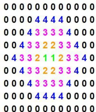
6 Similar to RGB data, depth data is also represented as a two-dimensional matrix. But
instead of each cell of the grid being pixels, each cell is a numeric representation of the distance
from the camera to the objects in front of the camera. Figure 2 below is an example of what a
depth matrix of a sphere in front of a depth sensing camera would look like. You can see that the
center of the sphere has a distance value of 1, since it is closest to the camera, and where the
distance from the camera is greater, such as the sides of the sphere, the distance values gradually
increase to 4. When the distance from the camera is farther than the range that the camera can
detect, the distance value is set to 0.
7 The Intel RealSense camera polls for depth data many times per second, depending on
what the setting is. This creates a stream of depth data, which is a continuous output of depth
data, frame after frame, similar to how a video is created from a stream of images played in rapid
succession.
The second important piece of technology I used for my project is the Unreal Engine 4
game engine (“Unreal Engine”, 2017). Unreal Engine 4 is a piece of software used primarily to
build video games. With the rise in popularity of virtual reality in recent years, it is now one of
the most popular tools to use to build virtual reality experiences. For my project, I needed some
software to be able to visualize the depth data that was streaming from the Intel RealSense
camera, and ultimately decided on using Unreal Engine 4 due to its popular use for building
virtual reality experiences, which my project could be integrated with, and also because the
scripting language the game engine uses is the same programming language that the Intel
RealSense library software is written in. With compatible programming languages, integrating
the Intel RealSense library with my Unreal Engine project would be a lot less daunting than
attempting to integrate the library with another game engine that uses a different programming
8
Design and Implementation
What I did first in my project was convert the stream of depth data that was represented
as numeric two-dimensional matrices to a series of three-dimensional objects where the depth of
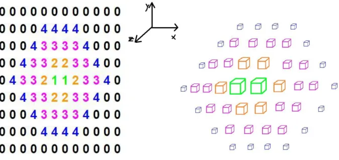
objects in front of the Intel RealSense camera can be visualized in three-dimensions. Figure 3
below shows how the numeric depth matrix of the sphere shown earlier in Figure 2 would look
like when converted to a three-dimensional format.
Figure 3. A three-dimensional representation of the depth matrix in Figure 2.
In Figure 3, each depth value from the matrix in Figure 2 has been converted to a cube a
certain distance away from a flat two-dimensional plane. It can be thought of a “pop-out” version
9 The color of each cube in the three-dimensional form corresponds to the colors of the depth
values in the depth matrix. The closest part of the sphere was the center of the sphere, colored in
green, so it has the lowest distance value of 1 and appears closest to the screen in the
three-dimensional form. Similarly, the farthest part of the sphere, colored in blue, has the highest
distance value, and appears farthest from the screen in the three-dimensional form.
The choice of a cube as an object to represent the depth data is not arbitrary. Cubes are
one of the lowest polygon objects there are to render. The depth matrix in figure 2 is actually an
order of magnitude smaller than the actual depth matrix the Intel RealSense camera grabs. The
depth matrix resolution that I have set the camera to stream at is 640 by 480, which is a matrix
with a length of 640 cells and width of 480 cells. This results in a matrix with 312,000 cells!
Since each cell needs to be converted to a three-dimensional object, I had to choose an object
with as little polygons as possible to maximize the program’s performance. More complicated
objects such as spheres are rendered using more polygons, and more polygons would mean more
work for the computer’s GPU (graphics processing unit). When the GPU under too much load, a
frame rate slowdown tends to occur, which is the leading cause of nausea in virtual reality and
should be avoided.
To convert the depth data streamed from the Intel RealSense camera to cubes spawning
in the Unreal Engine 4 project, I first linked in the Unreal Engine project to the Intel RealSense
library called librealsense, which is an open source library published by Intel that allows
developers to access and control certain aspects of Intel RealSense cameras. I lowered the default
camera resolution from 1080p to 640 by 480, so that the number of cubes that would be needed
to render would be greatly reduced. Then, I grabbed the depth data that the camera grabbed every
10 of my project resides (RealsenseData.cpp) could access it. With the Unreal Engine project now
having access to the Intel RealSense depth data, I was then finally at the point where I could start
spawning the cubes. However, the format that the depth data was stored was a bit different than
what I expected. Since visually, the data is represented as a two-dimensional matrix, I expected
the data to be stored in a two-dimensional array data structure, where each cell of the matrix
could be accessed with two sets of square brackets referring to the row and column of the data
you wish to grab. However, the data was actually stored in just a long one-dimensional array.
Fortunately, I have dealt with two-dimensional arrays “flattened out” as one-dimensional arrays before in my parallel computing class, so it wasn’t too difficult to perform operations on the
array despite its alternate form, but it was definitely more tedious.
With more than 300,000 cubes to render, I knew before I even wrote a single line of
rendering code that the frame rate would be awful and that there must be some best practices for
rendering such a large number of objects. After voicing my concern on an online community of
Unreal Engine users, the Unreal Engine subreddit (“unreal engine”, 2017), I was told that I could
look into something called Instanced Static Meshes, which could greatly increase performance.
The user who told me about it sent me a link to a video on YouTube with someone
demonstrating how to use Instanced Static Meshes in an asteroid belt simulation that also used a
large number of objects as asteroids (“UE4 Optimization: Instancing”, 2016). Instanced Static
Meshes are objects that Unreal Engine sees as copies as each other, so instead treating each
object as a unique object that is rendered uniquely, each object is rendered at the same time.
Since my cubes will all have the same dimensions, making them Instanced Static Meshes made a
11 The YouTube tutorial was done using Unreal Engine’s Blueprint System, which can be
viewed as a second, and sometimes preferred scripting language for Unreal Engine, depending
on the use case. Most of my logic was written in C++, but to follow the tutorial, the part of my
code that uses the cubes and Instanced Static Meshes and spawns them was also written in using
Blueprints.
Both the Intel RealSense camera and the Unreal Engine project perform operations many
times a second. The camera grabs about 30 frames of depth data per second, and Unreal Engine
renders at an even faster rate. To make the hand tracking smooth, in the function that Unreal
Engine calls every frame, Tick(), I looped through the current frame that the camera has grabbed,
for each cell, I spawned a cube placed in a coordinate associated with the row and column
number of the cell, and a distance z away from the x, y plane. For example, the cell on the top
left corner of the grid would have coordinates (1, 1), and the distance value of the cell would be
how many units of distance away from the x, y plane the cube will spawn.
With the cube spawning logic in place, the Instanced Static Meshes setup, and some
coordinates tinkering, I finally had my first successful run. The cubes in the Unreal Engine
would match my hand gestures in front of the camera as if I were in front of a mirror. However,
the frame rate was unbearably slow. That was not unexpected. The next step was optimizing the
project to increase the performance and drive up the frame rate.
The number one factor of low frame rate is too many polygons to render. I needed to cut
down on the number of cubes that are being spawned. The first optimization I made was making
12 matrix that are out of the camera’s range and do not provide any useful data. This cut down a
large number of cubes that needed to be rendered.
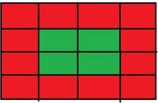
I noticed that the vertical and horizontal range of the camera was quite wide –
unnecessarily wide for simple hand tracking purposes. However, the 640 by 480 resolution was
the lowest resolution I could set for the camera. To further reduce the number of cubes that
needed to be spawned, I reduced number of cells in the depth matrix that the cube spawning
algorithm scanned though, grabbing the center 25% of the cells. Figure 4 shows a visualization
of the cells I kept (green) and the cells I skipped (red). This reduced the total number cubes I
needed to render by 75%! Leaving a maximum of 78,000 of the 312,000 cubes.
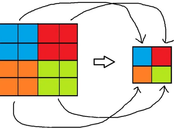
13 With the 78,000 cubes, the performance has improved, but not enough to make the
project run smoothly. To even further reduce the number of cubes that needed to be rendered, I
applied an image decompression technique I learned from my computer vision class, which
averaged each neighboring four distance values in the depth matrix to create a new matrix that is
a fourth of the size of the original matrix. Figure 5 shows an example of this. The groups of 4
pixels on the left are averaged to form the single pixel of the same color on the right. This
reduced the number of cubes needed to be rendered by another 75%, bring the 78,000 cubes
down to 19,500 cubes.
14 With just 19,500 cubes remaining, the frame rate of the project went up considerably –
enough for the hand tracking to run smoothly! There was one more issue that needed to be
addressed, however. There was a significant amount of noise in the project. A bunch of cubes
were popping up at random places and random times throughout the tracking. This is most likely
due to the infrared rays from the camera bouncing off surrounding objects and causing a slight
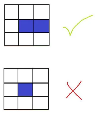
interference to the tracking. To reduce the noise, I wrote an algorithm of my own for it. My
algorithm would eliminate single isolated cubes from spawning by checking to see if the cube
has any neighboring cubes. Each cube can have a maximum of eight neighbors, two vertically,
two horizontally, and four diagonally. In the top group of cubes of Figure 6, the center cube has a
neighbor on its right, while the bottom group of cubes of figure 6 has a center cube with no
neighbors.
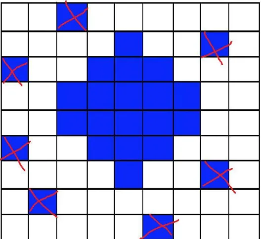
15 My algorithm would parse through all values of the depth matrix and set all cells that have all
eight of its neighbors with a value of 0, to 0. A cube with no neighbors is the same as a cell of
the depth matrix that has all eight of its neighbors with a value of 0. Figure 7 shows an example
of a depth matrix represented with blue and white pixels with several noise pixels that would be
removed by my algorithm. Blue pixels are cells with non-zero depth values, white pixels are
cells with depth values of 0. All of the cells that have been crossed out are noise -- all of their
neighbors are white cells, which are 0 valued cells. The filtered image would have all the
crossed-out cells removed, leaving only the center piece of the depth matrix that represents the
object.
16 With the noise filtering algorithm applied, there was another slight bump in improvement in
performance, but best of all, there was noticeable noise reduction when the project is run. With
that, the final optimization of my project has been implemented. At its current state, the project is a smoothly running hand visualizer that can accurately mimic a user’s hand movements and
gestures in front of a depth sensing camera. A still frame of the project is shown in Figure 8
below.
17
Societal Impacts
With what I have put together for this Intel RealSense and Unreal Engine hand tracking
project, anyone who is curious about how to get some basic hand tracking working using depth
data now has a public reference point that they can going through line by line on my GitHub
profile where I’ve uploaded the project (“UE4 Intel RealSense Hand Tracking”, 2017). I strongly
believe that this wave of interest in virtual and augmented reality is here to stay this time, and
that there will be more research and interest in hand tracking due to this as well. Hopefully, those
interested in building their own hand tracking solution could see that it is not too difficult to get a
basic version of hand tracking working based on what I have shown. Many more computer
vision and machine learning algorithms can be applied to my project to make it even more
effective.
Future Work
There is actually quite a lot more that could be done to increase the efficiency of my
project. An experimental idea I had when I first started this project was to use multiple cameras
facing the hand in various angles to create an even more complete three-dimensional model of
the hand. However, doing so using the cube spawning method I have done would most likely
result in multiple times more cubes than what a single camera would require. More optimizations
would be needed in order for the program to perform efficiently. With machine learning, the
program could be trained to recognize certain patterns of depth data and match the data to
18 experience. My artificial intelligence professor has expressed interest in my project and may ask
his students to build upon my project in his classes!
Conclusion
My goal for this project was to build a hand tracking solution from scratch using depth
data provided from the Intel RealSense depth camera and I believe have a succeeded in doing so.
The difficult part of this project was more due to my unfamiliarity with the software tools and
libraries, and not so much due to the complexity of the implementation and design. The courses I
have taken at Cal Poly through the Liberal Arts and Engineering Studies program has greatly
contributed to my ability to complete this project. Thanks to the coursework I have done, many
problems I have encountered in this project were ones I have encountered before. For those
problems that I have not encountered before, the problem-solving skills I have picked up over the
years were sufficient to overcome them. I hope that my project will contribute to the research in
19
References
Record $2 billion AR/VR investment in last 12 months. (n.d.). Retrieved March 25, 2017, from
http://www.digi-capital.com/news/2016/07/record-2-billion-arvr-investment-in-last-12-months/
Intel® RealSense™ Technology. (n.d.). Retrieved March 25, 2017, from
http://www.intel.com/content/www/us/en/architecture-and-technology/realsense-overview.html
Pikachu Pixel Art Grid. (n.d.). Retrieved March 25, 2017, from
http://hama-girl.deviantart.com/art/Pikachu-Pixel-Art-Grid-264575348
Make Something Unreal. (n.d.). Retrieved March 25, 2017, from
https://www.unrealengine.com/what-is-unreal-engine-4
Unreal Engine • r/unrealengine. (n.d.). Retrieved March 25, 2017, from
https://www.reddit.com/r/unrealengine/
UE4 Optimization: Instancing. (2016, November 06). Retrieved March 25, 2017, from
https://www.youtube.com/watch?v=oMIbV2rQO4k
Lang, G. (2017, March 14). Glang/UE4_Intel_RealSense_Hand_Tracking. Retrieved March 25,