with application program
Times Groups/1
Page
1 Introduction 5
1.1 Product and functional description . . . 5
1.2 Brief description of the application programs of the AB/S 1.1 . . . 6
1.2.1 Logic Time 200 IO/1 . . . 6
1.2.2 Logging/1 . . . 7
1.2.3 Times Groups/1 . . . 8
2 Device technology 9 2.1 Technical data . . . 9
2.2 Device connection . . . 9
3 Application and planning of Times Groups/1 10 3.1 Area of application . . . 10
3.2 The application program Times Groups/1 . . . 10
3.2.1 System requirements . . . 10
3.2.2 Delivery format . . . 10
3.2.3 Reading in the application program Times Groups/1 . . . 11
3.3 The programming software PZM 1 for the system user . . . . 11
3.3.1 System requirements . . . 11
3.3.2 Delivery format . . . 13
3.3.3 Installation of the parameterisation software PZM 1 . . . 13
4 Working with the application program Times Groups/1 14 4.1 Introduction . . . 14
4.2 Working with the context-sensitive Help function . . . 14
4.3 Starting the application program . . . 16
4.4 Parameterisation interface of Times Groups/1 . . . 17
4.4.1 Title bar . . . 17 4.4.2 Menu bar . . . 17 4.4.3 Toolbar . . . 22 4.4.4 Selection area . . . 23 4.4.5 Table area . . . 24 4.4.6 Status bar . . . 24
5 Parameterisation of the application program Times Groups/1 25 5.1 Procedure . . . 25
5.1.1 Working in the table area . . . 27
5.2 General . . . 28
5.2.1 Min. telegram interval . . . 28
5.2.2 Operating mode of clock . . . 28
5.3 Time switch program . . . 32
Page
5.4 Week routine . . . 40
5.5 Daylight saving times . . . 41
5.6 Special days . . . 43
5.7 Overview . . . 45
5.8 Groups . . . 47
5.8.1 General information about groups . . . 47
5.8.2 Properties of groups . . . 47 5.8.3 Table of groups . . . 51 5.8.4 Group trigger . . . 53 5.8.5 Group member . . . 56 5.9 Group addresses . . . 59 5.10 Utilisation . . . 62 6 Rectifying problems 64 6.1 Using the context-sensitive Help function to rectify problems . . . 64
6.2 Behaviour on bus voltage failure . . . 64
6.3 Behaviour after bus voltage recovery . . . 64
6.4 Technical hotline . . . 65
7 Glossary 66
1
Introduction
1.1 Product and functional description
The application unit is a DIN rail mounted device for insertion in the distribution board. The connection to the EIB is established via a bus connecting terminal at the front of the device.
The device can be downloaded with application programs with the aid of ETS2 from version 1.1 and can execute functions which are required in building system technology.
For example:
Using the application program Logic Time 200 IO/1, gates and timing ele-ments can be positioned in a very simple way using an integrated graphical interface in ETS2 and then linked in order to implement control systems. The application program Logging/1enables textual information to be printed out via the ABB i-bus®EIB to one or more logging printers. The printers are connected via RS 232 interfaces which are downloaded with the correspon-ding application program. A typical application is the printing out of faults that have occurred in the relevant services.
The application program Times Groups/1contains a year time switch pro-gram which allows day routines and week routines to be defined individually. The end user can modify the time switch program that has been created by the installer under WindowsTM.
SK 0010B98
The application Logic Time 200 IO/1 is parameterised clearly and con-veniently using the integrated graphical interface in ETS2. The configured application can be provided with comments and printed out for documentati-on purposes.
The application has the following basic functions available:
– 200 communication objects can be selected as inputs or outputs and allow up to 250 associations. The object type can have various formats (from 1 bit to 2 bytes).
– 50 gates can be defined as AND, OR or XOR, each with up to 8 inputs and 1 output. The inputs and outputs can be negated. Logic operations can be implemented with these gates.
– 50 gates that are controlled by a control input can switch through various object values from 1 bit to 2 bytes; filter functions are likewise available. It is thus possible to configure partition wall functions.
– 30 timing elements and staircase lighting functions which can be set bet-ween 0 and 18 hours are available for ON or OFF delays. The staircase lighting functions are configured automatically and are very simple to use.
1.2 Kurzbeschreibung der
Anwendungsprogramme vom AB/S 1.1
1.2.1 Logic Time 200 IO/1
1.2 Brief description of the application programs of the AB/S 1.1
1.2.2 Logging/1 The application program is intended for the output of textual information on logging devices (e.g. printer or PC with terminal emulation).
The printing of the log is triggered by the modification of the assigned object value. The printout contains the object value, date, time and the user text that has been entered.
The object type is freely selectable: 1, 2, 4 bit or 1, 2 byte objects can trigger the printing of the log and the object value is printed out. 50 individual blocks of user text can be assigned to 50 objects.
The output is carried out at the logging device via the EIB and an RS 232 interface and is possible at any point on the bus cable. Using the application program, an application unit can communicate with up to ten RS 232 inter-faces via the EIB.
The RS 232 interface e.g. EA/S 232.5 uses the application program
”Logging/3“.
A typical application is the printing out of faults that have occurred in the relevant services. General fault Sensor e.g. ET/S 6.24.1 ET/S 6.24.5 Application unit AB/S 1.1 Printer for electrical faults Assigning parameters with ET/S Printer for equipment faults EA/S 232.5 EA/S 232.5 EA/S 232.5
The application unit AB/S 1.1 is used in EIBinstallations together with the application program Times Groups/1as a multi-channel time switch. As an installer of the installation, you can define and modify the parameters of the application program Times Groups/1using the parameterisation interface of the program.
You can store the time switch program created with the application program
Times Groups/1as a file with the extension .zm1and transfer it to the custo-mer on a data carrier.
The user of the installation has the following options with the parameterisati-on software PZM 1:
– read in the transferred file with the extension .zm1,
– modify the time switch program according to his requirements and downlo-ad it into the application unit via the EIB,
– store the modified time switch program as a file,
– read out and set the time and date in the application unit and read out specific information from the device.
2 Device
technology
2.1 Technical data
2.2 Device connection
Power supply – EIB 24V DC, via the bus line
Operating and display elements – (Red) LED and push button For assignment of the physical address
Type of protection – IP 20, EN 60 529
Protection class II
Ambient temperature range – Operation – 5 ° C ... 45 ° C
– Storage – 25 ° C ... 55 ° C – Transport – 25 ° C ... 70 ° C
Connections – EIB Bus connecting terminal (black/red)
Design – Modular installation device, proM
Housing, colour – Plastic housing, grey
Mounting – on 35 mm mounting rail,
DIN EN 50 022
Dimensions – 90 x 36 x 64 mm (H x W x D)
Mounting width/depth – 68 mm/ 2 modules at 18 mm
Weight – 0.1 kg
Certification – EIB-certified
CE norm – in accordance with the EMC guideline
and the low voltage guideline
Description Ordering info. bbn Price Price Unit Pack
40 16779 group per unit weigght unit
Short code Product code EAN (kg)
1 Programming LED, push button 3 Bus connection
The application program Times Groups/1of the application unit AB/S 1.1 enables the installer to implement complex time switch programs for building automation via the EIB.
With the parameterisation software PZM 1, the user of the system can simply adapt the time switch program of the application unit AB/S 1.1to his require-ments and thus guarantee the flexibility of operation of the installation.
The application program Times Groups/1 enables the parameterisation of a time switch program for the application unit AB/S 1.1 by the installer of the system in connection with the ETS2 software from version 1.1 onwards. You can simply and clearly define and modify the parameters of the applicati-on program Times Groups/1with the help of the user-friendly graphical interface.
The parameterisation data is stored in the ETS2 database together with the project. The configured data can be printed as a list for documentation purposes.
You can store the time switch program created with the application program
Times Groups/1as a file and transfer it to the system operator on a data carrier.
The user of the installation can adapt the time switch program to his require-ments with the programming software PZM 1.
The following system configuration is required for the use of the application program Times Groups/1:
System configuration in accordance with the ETS2 reference manual EIBA Tool Software ETS2 V1.1 Service Release B (991025) or higher Microsoft Windows from version 95 / 98 / 2000 / ME / NT / XP upwards
The application program Times Groups/1 is on the ABB STOTZ-KONTAKT product data CD-ROM and is available as a download on the ABB STOTZ-KONTAKT home page www.abb.de/stotz-kontakt
3
Anwendung und
Planung von
Zeiten Mengen/1
3.1 Area of application 3.2.1 System requirements 3.2.2 Delivery format3
Application and planning of Times Groups/1
3.2.3 Importing the application program Times Groups/1
3.3 The programming software PZM 1 for the system user
3.3.1 System requirements
The importing of the application program Times Groups/1 is carried out in the usual way with ETS2 from version 1.1. onwards.
The programming software PZM 1is available for the user of the installation which makes it possible to adapt the time switch program created by the installer of the system to his own requirements.
The parameterisation software PZM 1runs under Microsoft Windows from version 95 / 98 / 2000 / ME / NT / XP upwards.
The user of the system has the following options with the parameterisation software PZM 1
– read in the file that has been transferred by the installer,
– modify the time switch program according to his requirements and download it into the application unit via the EIB,
– store the modified time switch program as a file, – print out the time switch program completely or partially
– read out and set the date and time in the application unit and read out specific information from the device.
The following system configuration is required for the use of the parameteri-sation software PZM 1:
Hardware:
CPU Pentium 133 MHz Hard disk 64 MB RAM CD-ROM drive
One free serial interface Printer
A connecting cable and an RS 232 interface e.g.EA/S 232.5is required for data transfer between the PC and the application unit AB/S 1.1.
The connecting cable links the serial interface of the computer (COM1 or COM2) with the RS 232 interface of the EIB installation. The RS 232 interface establishes the connection with the bus.
Connection to a PC with D-SUB-9 socket connector
The connecting cable must be wired 1:1 if the PC interface is designed as a 9-pole D-SUB plug.
Connection to a PC with D-SUB-25 socket connector
If the PC interface is designed as a 25-pole D-SUB plug, an adapter or an appropriate connecting cable is required for the link to the 9-pole terminal of the RS 232 interface.
3.3.2 Delivery format
3.3.3 Installation of the parameterisation software PZM 1 Software:
Microsoft Windows from version 95 / 98 / 2000 / ME / NT / XP upwards Parameterisation software PZM 1
The parameterisation software PZM 1for the system user can be found on the ABB STOTZ-KONTAKT CD-ROM under ”Software“ and is available as a download on the ABB STOTZ-KONTAKT home page www.abb.de/stotz-kontakt
Prerequisites
Familiarity with Microsoft Windows™is a prerequisite in this manual.
A detailed description of the operation of this program is therefore not inclu-ded. We refer you in this context to the appropriate information in the Microsoft Windows manual and the corresponding specialist manuals.
Installation
The parameterisation software PZM 1 is installed using the following steps: (a) Open the directories Softwareand PZM 1in succession on the CD-ROM
using Windows Explorer. Start the file setup.exewith a double click and follow the instructions of the setup program on the screen.
(b) Start the file downloaded by the ABB STOTZ-KONTAKT home page and follow the instructions of the setup program on the screen.
4
Working with the application program Times Groups/1
4.1 Introduction
4.2 Working with the context-sensitive Help function
The parameterisation of the application program Times Groups/1is carried out directly in ETS2 from version 1.1 onwards using a graphical project design module which significantly simplifies the input of parameters and the overview.
When calling up parameters in the device view of ETS2, the graphical project design module is started and ETS2 switches to the background. When exiting the module, the configuration data is stored in the ETS2 database and the ETS2 window Edit Deviceis displayed again.
The context-sensitive Help function provides the necessary information for each step involved in the parameterisation of the application program
Times Groups/1.
The Help function is retrieved as follows: – Press the Helpbutton in the dialog window or
– Press the right mouse button in the table area and select Help about
– Press F1on the keyboard or
– Press the Helpbutton in the toolbar.
The following procedure is the best way of using the application program
Times Groups/1and its Help function:
First start the ETS2 program and open the project which you wish to edit. Minimise the ETS2 main window and move it to the top right-hand corner. After starting the application program Times Groups/1, minimise the window and move it to the right-hand side of the screen so that about a third of the screen width remains free. Now call up the Help for Softwareoption and position the open window in the unoccupied area on the left-hand side.
When you call up the Help function for information, you can now see the relevant Help page on the left-hand side for each editing step. By clicking on the underlined terms marked in green, you can receive further explanations for these terms. You can return to the previous Help page using the Backbutton.
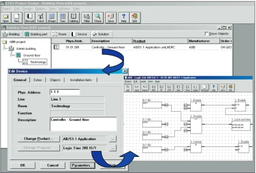
The graphical project design module of the application program is started from the ETS2 Building Viewwindow. The Edit Devicewindow appears by pressing the left mouse button on the device line followed by Parameters …
in the context menu or by double clicking on the device. You access the para-meterisation interface of the application program Times Groups/1by clicking on Parameters…
The title bar contains the WindowsTMiconsfor minimising, restoring/maximi-sing and clorestoring/maximi-sing the window as well as information about the manufacturer, name of the application program, the physical address, the type and name of the device.
The menu bar contains the selection menus File, Edit, Online, Windowand
Help.
4.4 Parameterisation interface of Times Groups/1
4.4.1 Title bar: 4.4.2 Menu bar:
Title bar
Menu bar
Toolbar
Selection area
Status bar
Table area
File selection menu
Some of the menu items are context-sensitive and are only activated in spe-cific configurations. Inactive menu items are greyed out.
Save
The parameterisation data is stored in the ETS2 database by selecting the menu item Save.
Export
By selecting Export, the time switch program can be stored as a .zm1file or in .csvformat. Select the required format from the list field.
Files with the extension .zm1can be imported into the parameterisation software PZM 1and then edited.
Files in .csvformat can be imported into other word processing or spreads-heet software where the parameterisation data can be edited and printed out.
Import
After selecting the menu item Import, the time switch program that has been exported from the application program Times Groups/1or the parameterisa-tion software PZM 1can be read in as a .zm1file.
When importing a .zm1file into an existing ETS2 project, the parameters stored in the edited project are overwritten.
It is important to note when importing the .zm1file that changes may have been implemented in the time switch program since the file was exported. It is therefore advisable to save the ETS2 project before each import.
The parameter settings can be printed out in table format by selecting Print.
View Page
Under View Page, you can display the layout of the parameterisation data on the screen before it is printed.
The menu item Filter Print Dataenables you to select the sections of the parameterisation which should be printed out.
Filter Print Data
Select the Allbutton if you wish to print out all the parameter settings. To print out specific sections of the parameterisation, choose the Selection
option, press the Ctrlkey and select the entries which you wish to print out with the left mouse button.
Printer Setup
The option Printer Setupallows you to select and configure a printer.
Close
By selecting Close, you can exit the application Times Groups/1and return to the Edit Devicedialog window in ETS. You are then requested to save the data if required. If you confirm the request, the parameter assignments are saved when you exit Times Groups/1. Then press the OKbutton in the Edit Devicedialog window.
Edit selection menu
Some of the menu items are context-sensitive and are only activated in spe-cific configurations. Inactive menu items are greyed out.
Newcreates either a new day routine, new switching time, new daylight saving time, new special day, new group, new group triggers or new group members, depending on the context.
Copycopies the marked line to the clipboard.
Insertpastes the contents of the clipboard as a new entry.
Deleteremoves the marked line.
Usageindicates the function of a marked parameter.
Online selection menu
The menu items Set Date/Timeand Show Statusare context-sensitive and are only activated in specific configurations. Inactive menu items are greyed out.
Set Date/Time
By selecting the menu item Set Date/Time, you can read out or set the date and time of the internal clock of the application unit.
A prerequisite is that the physical address and the application have previous-ly been downloaded into the application unit AB/S 1.1.
By selecting the menu item Set Date/Time, you can read out or set the date and time of the internal clock of the application unit. The relevant dialog window opens.
The current date and time of the PC are read and displayed automatically when the dialog field is opened.
With the buttons Read PC timeand Read AB/S time, you can update the fields Dateand Timeto match the corresponding time.
You can also enter a date and a time to set the time in the application unit. The date can be set in a range between 01/01/1970 and 31/12/2035. It is displayed as two-digit numbers which are separated in the format
day/month/year. Entries for the year between 36 … 69 are rejected.
There is a button to the right of the entry field for the date which enables the relevant pages of the calendar to be displayed for the current date.
The date can be entered either directly or by selecting a date in the calendar. Please note that the time switch is updated when the clock is adjusted and switching operations can be triggered as a result.
The accuracy of the internal clock is primarily dependent on the ambient temperature and it can gain or lose up to 1 minute per month. You can improve the accuracy of the internal clock by entering an offset value in the text field Adjust clock. If the clock for example gains 20 seconds during the month, this inaccuracy can be compensated by entering an offset value of – 20 seconds.
Show Status
After selecting Onlineand Show Status, the device status is read out from the application unit and a message field opens.
The message field indicates:
– the address of the application unit in the EIB installation
– the date and time when the parameterisation data was last downloaded into the application unit
– the status of the application program that is running in the application unit – the date and current time of the internal clock in the application unit – the status of the time switch program
– the current day routine
– the type of the current day routine
– the status of the summertime/wintertime conversion
The message field can be updated by pressing the Read Statusbutton. You exit the message field by pressing the Closebutton.
Window selection menu Split Horizontal
The window of the table view can be divided. The same parameterisation data is displayed in both partial views. This simplifies the copying of elements e.g. entries are copied into partial view 2 from day routine 5 and inserted into day routine 7 of partial view 1 using ”drag & drop“ or ”copy & insert“.
Toolbar
The toolbar can be activated or deactivated here.
Status Bar
The status bar can be activated or deactivated here.
Help selection menu
Help for Device
By selecting the menu item Help for Device, you can obtain a brief descripti-on of the hardware of the applicatidescripti-on unit.
Help for Application Software
This option gives you with comprehensive information about the application program Times Groups/1.
About
About …provides you with information about the application program
Times Groups/1.
The toolbar contains buttons with the most important commands for rapid retrieval with the mouse. The buttons are context-sensitive and only activated in specific configurations.
The toolbar can be activated or deactivated by pressing Toolbarin the
Windowmenu.
4.4.4 Selection area
Copycopies the marked line to the clipboard.
Insertpastes the contents of the clipboard as a new entry.
Printprints out the parameterisation data in table format.
Savestores the parameterisation data in ETS2.
Helpopens the Help function of the application program.
Closeexits the application program Times Groups/1. Asks if you wish to save the data.
The selection area on the left-hand side has a similar structure to the browser in WindowsTMExplorer. From there, you can select the table that is to be displayed or edited.
The table area on the right-hand side displays the table or view that has been marked in the selection area. Existing entries can be edited or deleted and new entries can be inserted.
When it is activated, it always forms the lower border of a window. It indicates for the current selection in the Table area, the number of elements that are still available for further entries.
The status bar can be activated or deactivated in the Windowmenu under the item Status Bar.
4.4.5 Table area:
5
Parameterisation of the application program Times Groups/1
5.1 Procedure The EIB installation is edited first of all in the usual way with the
ETS2 Project Designmodule.
The name of the group addresses is defined when parameterising to the EIB installation. It cannot be modified by the user of the installation with the para-meterisation software PZM 1at a later date.
You should select a name which indicates the usage to both yourself and the user e.g. ”Switch external lighting ON/OFF“
The functions which the application unit AB/S 1.1 should fulfil in the EIB installation e.g. day routines, switching times etc. should first be clarified with the customer and/or the operator of the system.
An application unit is imported into the project with the application program
Times Groups/1.
In the Edit Devicewindow in ETS, a comment should be entered for the system user in the Descriptionfield such as the project name, the function of the application unit in the installation, the date etc.
This information is displayed in the table area of the parameterisation soft-ware PZM 1as a ”Comment of the installer“ once the time switch program has been downloaded.
After starting the application program Times Groups/1, the group addresses that are required in the application unit AB/S 1.1should first be transferred from the ETS2 project so that they are available for selection from the list fields during the parameterisation.
It is however also possible to transfer a group address at a later stage during the parameterisation or define a new group address and then transfer it. See
Assign group address, Insert group address(Chapter 5.9).
The deletion and renaming of group addresses is only possible in the ETS2 program.
Once the parameterisation is concluded, download the application program into the application unit AB/S 1.1 with the ETS2 Commissioningmodule. Then set the internal clock of the application unit AB/S 1.1, see menu item
Online(Chapter 4.4.2).
Before handing over the EIB installation, export the time switch program as a .zm1 file and give them to the user of the installation together with an ABB product data CD-ROM which contains the parameterisation software PZM 1. You should now archive a backup copy of the .zm1 file on your PC. After importing a time switch program that has been modified by the customer, you can recreate the previous state if required by importing the backup copy of the original time switch program.
If later changes need to be made to the time switch program which cannot be carried out by the user e.g. insertion of a new device, you should proceed as follows:
– Open the original EIB project and carry out the required changes. – Open the application program Times Groups/1.
– Import the current .zm1 file which you have received from the user. The original time switch program that you created is overwritten by the new time switch program which includes possible modifications by the system user.
If this is not required or the time switch program of the user is no longer applicable or usable, you can revert back to your archive copy of the .zm1 file.
In this case, any changes that have been carried out by the user are lost when downloading the application unit AB/S 1.1 for the commissioning of the system extension.
– Configure the new function in the time switch program.
5.1.1 Working in the table area The selection area has a similar structure to the browser in WindowsTM
Explorer. By choosing the corresponding folder, you can select the table that is to be displayed or edited.
The table area displays the table or view that was marked in the selection area. Existing entries can be edited or deleted and new entries can be inser-ted.
Deleting an existing entry
Select one or more existing entries. Press the right mouse button and select
Deletefrom the pop-up menu or select Deletefrom the Editmenu in the toolbar. You are then asked to confirm the deletion. Close this message field with Yesto delete the entry or Noto cancel the deletion.
Editing an existing entry
Select one or more existing entries. Double click with the left mouse button or press the right mouse button followed by Editin the pop-up menu to open the relevant dialog window for editing the entry.
The dialog windows for editing existing entries can be closed by pressing the
OKand Cancelbuttons.
Any changes that have been carried out are adopted by pressing the OK
button, while pressing the Cancelbutton loses the changes.
Inserting a new entry
Select ***new entry***. Double click with the left mouse button or press the right mouse button and select Editfrom the pop-up menu. Alternatively, select the Editmenu followed by the menu item New xxxif available. This opens the dialog window for creating a new entry.
You can exit the dialog windows for inserting a new entry using the buttons
Insertand Close.
After pressing the Insertbutton, the new entry is inserted in the table and a further entry can be edited in the dialog window.
You can exit the dialog window without inserting the new entry by pressing the Closebutton.
Sorting in list fields
When creating new entries, the possible entries are chosen from list fields with one or more columns. To ease the selection, the columns can be moved in the list field and sorted into ascending or descending order. To move the column, click on the column header with the left mouse button and shift it to the right or left while keeping the mouse button pressed down. To sort in ascending order the list field is opened and you click on the columns that you wish to sort with the left mouse button. To sort in descending order, the Ctrl key must be pressed and held down before using the left mouse button.
Note:
The Utilisationlist field cannot be sorted.
The associated table area displays the general parameters of the application program Times Groups/1.
With the parameter Min. telegram interval, you can specify which minimum time interval should be used by the application unit for sending the bus tele-gram in succession. You can choose between:
– normal(default setting)
– 0.1 s; 0.2 s; 0.3 s; 0.4 s and 0.5 s
For example, if a minimum telegram interval of 0.5 s is selected and 5 tele-grams need to be sent, the last telegram is sent 2.5 s after the first telegram. The option normalmeans that no additional delay has been inserted.
5.2 General
If bus voltage recovery occurs within this period, the time switch program restarts automatically.
Once the power reserve has elapsed, the current date and time are lost and the time switch program is halted until the date and time are reset.
The behaviour of the clock of the application unit AB/S 1.1 on bus voltage recovery can be specified via the parameters.
The clock can be set automatically by a bus telegram from a master clock. Otherwise, the clock must be set via the application program
Times Groups/1or the parameterisation software PZM 1.
Note:
The time switch program is updated when the clock is adjusted and switching operations can be triggered as a result.
If the time switch program should start automatically after a bus voltage failure, the clock should be operated as a slave and the Group address for requestshould be assigned to a group address which requests the current time from a master clock.
Once the power reserve has elapsed, a cold start is carried out, whereby the assigned group address is sent and the current time is requested. The inter-nal clock is then synchronised to the master clock. The time switch program is updated and restarts.
Switching operations can be triggered as a result.
General information about the slave and master operating modes
If you have selected slave or master as the operating mode, the group addresses for the time, the date and for requesting the time and date is displayed – if they have already been assigned in ETS2.
If you have not yet assigned any group addresses with ETS2, the list fields display the default setting none.
You can assign a new group address in the list field or insert a new one. To do so, select new group address. The dialog window Add group addressesopens in which you can insert a group address in the usual way.
Select an existing group address or insert a new group address and exit the window by pressing Acceptor Close. You then return to the Generaltable area.
Operating modes of the internal clock
With the parameter Operating mode of clock, you can set the mode of the internal clock. You can choose between:
– Internal(default setting)
– Slave (always receive)
– Slave, OFF period (00:05…23:55 receive) – Master (send every minute)
– Master (send every hour) – Master (send daily)
Internal(default setting)
The internal clock cannot send the date and time on the bus nor be set via telegrams on the bus.
Slave (always receive)
The internal clock can be set or synchronised via a bus telegram e.g. from a master clock.
Slave, OFF period (00:05…23:55 receive)
The internal clock can be set between 00:05 and 23:55 and synchronised via a bus telegram e.g. from a master clock. Date and time telegrams are ignored during the period between 23:55 and 00:05. Synchronisation problems are thereby avoided when the day changes.
Master (send every minute)
The internal clock sends bus telegrams with the time and date once per minute e.g. to synchronise other EIB devices.
The date and time are also sent when the object Group address for request
is activated or deactivated.
If the internal clock is programmed as a master, it immediately sends bus telegrams with the new time and date on the bus, once the time has been set using the application program Times Groups/1. Further reactions can therefore occur in other EIB devices which are synchronised to the new date and time.
Master (send hourly)
The internal clock sends bus telegrams with the time and date once every hour e.g. to synchronise other EIB devices.
If the internal clock is programmed as a master, it immediately sends bus telegrams with the new time and date on the bus, once the time has been set using the application program Times Groups/1. Further reactions can there-fore occur in other EIB devices which are synchronised to the new date and time.
Master (send daily)
The internal clock sends bus telegrams with the time and date once every day e.g. to synchronise other EIB devices.
You are requested to enter a time (hour, minute) for the transmission.
The date and time are also sent when the object Group address for request
is activated or deactivated.
If the internal clock is programmed as a master, it immediately sends bus telegrams with the new time and date on the bus, once the time has been set using the application program Times Groups/1. Further reactions can there-fore occur in other EIB devices which are synchronised to the new date and time.
The time switch program sends bus telegrams with specific group addresses and values at the set intervals, thereby triggering specific functions in the EIB installation such as switching the lighting on/off in room 13.
It is therefore possible to define the day routines i.e. switching programs for specific days and the week routine i.e. the assignment of day routines to the days of the week in the time switch program.
In the time switch program, you can
– define 15 day routines i.e. 15 different time switch programs for the period between 00:00 and 23:59,
– define the week routine i.e. assign a day routine to each day of the week, – define the periods for the summertime conversion for 5 years in advance, – assign other day routines to 100 individual periods – so-called special days
– which deviate from the standard week routine, – display an overview of the time switch program.
5.3.1 Day routine A day routine contains the time switch program for a day between 00:00 and 23:59.
Within a day routine, the first telegram can be sent at 00:00 and the last telegram at 23:59.
Day routines can be activated and deactivated via the time switch program and/or a bus telegram (e.g. by pressing a bus push button).
If a new day routine is activated via a bus telegram, the current day routine ends i.e. the application unit sends a bus telegram containing the group address of the current day routine with the value 0 on the bus. A bus telegram containing the group addresses of the new day routine is then sent on the bus with the value 1. It is therefore possible to show e.g. on an LC display which day routine is currently active.
The application unit then sends bus telegrams if required and creates the exact state in the EIB installation that would have existed if the old day routi-ne had run until midnight as normal and the routi-new day routirouti-ne had started at midnight and had then been carried out until the current time.
If a day routine has been activated and the clock is put forward, the exact state is then created in the EIB installation that would have existed if the day routine had run normally until the new time.
No bus telegrams are sent if the clock is put back.
If the time is adjusted so that a new day routine is activated, the sequence is carried out as described for a change in the day routine.
First select Time switch programin the selection area, followed by
Day routines.
The list of day routines that have already been inserted is displayed in the associated table area.
This table displays the consecutive number of the day routine (DR No.)and the name of the day routine (DR Name).
If a bus telegram can activate a day routine, the associated number (GA No.)
and name (GA Name)of the group address is displayed which can activate or deactivate this day routine.
You can delete or edit existing day routines or insert new day routines.
Edit day routine
Select an existing day routine in this list or select ***new day routine***or press the right mouse button and select New day routinefrom the pop-up menu.
Enter a new name in the Day routinedialog window or modify an existing name.
Day routines can be activated or deactivated by the time switch program and/or a bus telegram (e.g. by pressing a bus push button).
If it should be possible to activate the day routine both via the time switch program and a bus telegram, then select the checkbox Trigger via bus. In this case, a further list field is opened where it is possible to select and insert a group address that has previously been defined and adopted in ETS2.
This list only contains the group addresses that are available for the current dialog.
The Typeindicates which type of values can be sent by a bus telegram with this group address.
The Nameof the group address is defined when assigning parameters to the EIB installation and cannot be modified with the parameterisation software. The Numberof the group address is the unique identifier of a group address. This list can be rearranged and sorted as required.
It is also possible to adopt a group address that is not contained in the list. Click on New group addressto open a window in which you can insert a group address as in ETS2.
After editing the subgroup, the entry should be confirmed with OK. Select the group addresses that are to be accepted and then press the Acceptand
Closebuttons in sequence. You then return to the Day routinedialog window.
5.3.2 Switching times of the day routine
I
The list is displayed in the table area, extended by the newly inserted day routines.
The point at which the time switch program of the application unit sends a bus telegram with a defined group address and value on the bus is designa-ted as a switching time.
Edit switching time
In the selection area, click on Time switch program, Day routinesand then select a day routine.
The list of inserted day routines appears in the associated table area.
You can see at what time a bus telegram should be sent with a specific group address and a specific value.
tele-You can delete or edit existing switching times or insert new switching times. Select an existing switching time in this list or select ***new switching time***or press the right mouse button and select New switching time
from the pop-up menu.
The relevant dialog window opens after double clicking with the mouse.
In this dialog field you define
– at what time a bus telegram is sent, thereby activating a function, – which group address is sent with this bus telegram and which function is
thereby activated,
– which object value is sent with this bus telegram, thereby e.g. switching the light ON or OFF.
From the list of group addresses, select the group address which should be sent at the specified time.
It is also possible to adopt a group address that is not contained in the list. Click on New group addressto open a window in which you can insert a group address as in ETS2.
After editing the subgroup, the entry should be confirmed with OK. Select the group addresses that are to be accepted and then press the Acceptand
Closebuttons in sequence. You then return to the Switching timedialog window.
With the option Send on change only, you define that a bus telegram is only sent if the value differs from the last value sent e.g. if the light should be switched on and is already on, this bus telegram is not sent.
Close the dialog window Switching time for day routine… via the
Insert/Closebuttons.
The list is displayed in the table area, extended by the newly inserted switching times.
Select Time switch programin the selection area followed by
Week routine.
This table displays the days of the week together with their associated day routines.
If a day routine has not yet been assigned to a weekday, there is no day routine number and noneis entered as the name.
You can assign a day routine to the day of the week or delete an existing association.
Edit week routine
Select an existing day routine in this list or ***none***.
The associated dialog window opens after double clicking with the mouse.
Select the day routine which you wish to assign to the weekday from the open list field.
Close the dialog window using the OKor Cancelbuttons.
5.5 Daylight saving times Select Time switch programin the selection area followed by Daylight saving times.
This table displays the time periods for the summertime conversion which have already been defined.
In this table, you can see the year of the summertime conversion, the start and end of the daylight saving time as well as the offset.
You can delete and edit existing entries or insert new periods.
Edit daylight saving time
Select an existing daylight saving time in this list or select ***new daylight saving time***or press the right mouse button and select New daylight saving timefrom the pop-up menu.
In this dialog field, you can define and calculate new periods for the conversi-on from summertime or modify existing entries.
First select the year and press the Calculatebutton to determine the start and end of the daylight saving time.
These times are calculated according to the conversion rules that are stored in your version of WindowsTMfor changing from standard time to summer-time.
You can also enter or modify the Startand Endof the daylight saving time yourself as well as the Offseti.e. the time adjustment. At the start of the daylight saving time, the current time of the internal clock is adjusted by this value and reset at the end of this period.
The date for the start and end can be set in a range between 01/01/1970 and 31/12/2035. It is displayed as two-digit numbers which are separated in the format day/month/year. Entries for the year in the range between 36 and 69 are rejected.
There is a button to the right of the entry field for the date which enables the relevant page of the calendar to be displayed for the current date.
The date for the start and end of the daylight saving time can be entered either directly or by selecting a date in the calendar.
Close the dialog window via the Insert/Closebuttons.
The list is displayed in the table area, extended by the newly inserted daylight saving times.
5.6 Special days Individual days or time periods which deviate from the normal week routine are called special days.
Select Time switch programin the selection area followed by Special days. The associated table area displays the list of special days which have already been defined.
This table indicates the start and end of the time periods which have already been defined as special days as well as the day routine which have been assigned to them.
You can delete and edit existing special days or insert new special days.
Edit special days
Select an existing daylight saving time in this list or select ***new special day***or press the right mouse button and select New special dayfrom the pop-up menu.
By entering the date and time, you define the Startand Endof the time period which deviates from the normal week routine.
The date for the start and end can be set in a range between 01/01/1970 and 31/12/2035. It is displayed as two-digit numbers which are separated in the format day/month/year. Entries for the year in the range between 36 and 69 are rejected.
There is a button to the right of the entry field for the date which enables the relevant page of the calendar to be displayed for the current date.
The date for the start and end can be entered either directly or by selecting a date in the calendar.
Select a day routine from the list of day routines and close the dialog window via the Insert/Closebuttons.
Overlapping of periods
If a new special day has been entered and the period of the new special day coincides with periods that have been already been defined for other special days, the following message appears.
With the selection New overlaps old, the new entry coincides with existing entries in the same time period (see examples).
With the selection Old overlaps new, the new entry does not coincide with existing entries in the same time period (see examples).
Example 1 Example 2 Old entry
New entry
New overlaps old
Old overlaps new
Select the option required.
The list is displayed in the table area, extended by the newly inserted special day.
If the periods overlap, you now see the list with the correction you have selec-ted.
Select Time switch programin the selection area followed by Overview. An overview of the use of a specific group address can be displayed in the associated table area.
DR 1 5.7 Overview DR 1 DR 1 DR 2 DR 2 DR 1 DR 1 DR 2 DR 2 DR 1 DR 2 DR 2
Show overview
So that all the elements of the table area are visible, it is advisable to maximi-se the window until the horizontal scrollbar disappears.
Select a group address (function) from the list field Group addressand a time period and then press the Showbutton. You can display in a table the time intervals at which bus telegrams are sent with this group address and the values which are sent with these bus telegrams.
The date for the Time frame from … tocan be set in a range between 01/01/1970 and 31/12/2035. It is displayed as two-digit numbers which are separated by in the format day/month/year. Entries for the year in the range between 36 and 69 are rejected.
There is a button to the right of the entry field for the date which enables the relevant page of the calendar to be displayed for the current date.
The date for the start and end can be entered either directly or by selecting a date in the calendar.
If the entry SoCis marked with a tick, a bus telegram is only sent if the value has changed i.e. if the light has already been switched on and should remain switched on, this bus telegram is not sent.
The following information is indicated in the table for the selected group address:
– the date and time when a telegram is sent,
It is defined in the time switch program when bus telegrams are sent with specific group addresses and specific values on the bus.
If several bus telegrams with specific group addresses and values should be sent repeatedly at certain times, they can be combined into a Group.
e.g. at 15:00, 16:00, 17:00 and 18:30, the lighting in Room 1, Room 2 and Room 3 should be switched on and the blinds in Room 1, Room 2 and Room 3 should be lowered.
The group addresses and values that are assigned to these functions can now be combined into a group e.g. "Room 1, 2, 3”. This group can therefore also be designated as a functional group and the combined group addresses are called Group members.
In the time switch program, it is therefore only necessary to enter the group address of a trigger for this group e.g. with the name "Room 1, 2, 3” in order to send bus telegrams on the bus that contain the group addresses (group members) and values that have been combined.
The group address that triggers a group is called a Group trigger. You therefore save time when assigning parameters and the time switch program becomes clearer.
Group number
The group number (GR No.)is automatically assigned by the application program Times Groups/1and is a consecutive number which acts as a unique identifier for the group.
Group name
The group name (GR Name)can be freely selected and can for example describe which functions are activated by this functional group or which parts of the building are influenced by triggering the group.
Type
A group can be activated by a bus telegram with the group address of a trigger for this group. Various types of values can be sent with this bus tele-gram, e.g. 1 bit values i.e. binary values such as 0 and 1 or e.g. 8 bit values such as 0, 128 or 255 which can then be interpreted as 0%, 50% and 100%. The Typeidentifies which type of value is assigned to the trigger of a functio-nal group i.e. whether the group is triggered by a telegram with the binary value 1 or by a telegram with the 8 bit value 128.
5.8 Group
5.8.1 General information about group
Trigger
If a group is triggered by a Group trigger, specific functions are activated e.g. switching the light ON or OFF. It is therefore possible for example when triggering a group to switch the light off in specific rooms with the value 0 and to switch the light on in these rooms with the value 1. A group can therefore behave differently when triggered by the value 0 rather than by the value 1. You could therefore designate the triggering of a group by the value 1 as an activation of the (functional) group and the triggering of the group by the value 0 as a deactivation of the (functional) group.
Binary values which trigger a (functional) group can only accept the values 0 and 1. If the group is triggered e.g. by an 8 bit value, the trigger values can lie in a range between 0 and 255 or between 0% and 100%.
Value ranges can therefore be entered for both the activation and deactivati-on of a group.
Those values which activate a group or in other words trigger within range A are entered under Range Awhile Range Bcontains those values which deactivate a group or trigger within range B.
If a group is triggered e.g. by a 2 byte value with which the room temperature of a room is transmitted, the blinds can for example be opened at a tempera-ture value below 22 °C and both the air conditioning and lighting can be switched off. At a temperature above 24 °C, the blinds can be closed and the lighting and air conditioning switched on.
It is possible to define further criteria for the group trigger to prevent this group e.g. from being triggered and thereby activating specific functions each time that identical values are sent repeatedly.
Condition
The entry A, B (always)means that the group will always be triggered if the trigger value lies within range A or B. If a bus telegram is received several times with the same value or with values in the same range, the group would be triggered after each transmission.
Using the above example, if the temperature value 21 °C is sent several times in succession, the group is activated each time and bus telegrams are therefore sent each time to open the blinds and to switch off the air conditio-ning and lighting.
The entry ->A,->B (new entry)means that the group is only triggered the first time that the trigger value is in range A or B. If the same value is sent several times to the application unit AB/S 1.1, the group is only triggered after the first transmission.
If the group was triggered last time by the transmission of a value in range A e.g. 21 °C and values were then sent outside of range A e.g. 23 °C followed by a value in range A again e.g. 21 °C, the group is reactivated by the first transmission of the value 21 °C. Bus telegrams are sent to open the blinds and to switch off the air conditioning and lighting.
The entry A<->B (hysteresis)means that the group is only triggered if the trigger value is first in range A and the last triggering was carried out by a value in range B or if the trigger value is first in range B and the last triggering was carried out by a value in range A.
If the group was last triggered by a value in range A e.g. 21 °C (the group is activated e.g. in order to switch on the heating) and values outside of range A were then sent e.g. 23 °C followed by a value in range A e.g. 21 °C, the group is no longer activated by this value. A new activation only takes place if a value is transmitted that lies in range B i.e. above 24 °C (the group is deactivated e.g. in order to switch off the heating).
21°C 24°C 23°C >B <A Deactivate group (heating OFF) Activate group (heating ON) A<->B Activate group (heating ON)
Warm start and Cold start
Current information that is saved in the application unit, e.g. Group 1 is trig-gered, is stored for at least 1 hour after a bus voltage failure. If the bus volta-ge failure lasts lonvolta-ger than 1 hour, the application unit automatically detects whether the information is still saved or whether a data loss has occurred. The application program and the parameters are permanently stored in the application unit.
In the event of a data loss, the application unit carries out a so-called
Cold start on bus voltage recovery i.e. it can no longer access stored data and must either work with predefined data or read out the relevant data from other bus devices.
It should further be noted that the time switch program does not start up automatically after a cold start as the current time or the date are no longer available. See also internal clock.
If the stored data is still available, the application unit carries out a Warm start on bus voltage recovery i.e. it can work with the stored data but can also use predefined data or read out the relevant data from the other bus devices.
The reaction of the application unit to both a cold and warm start can be defined.
Bus (read value)
The application unit reads out the relevant data from other bus devices after bus voltage recovery. Depending on the received value and the criteria for triggering the group, it either triggers or does not trigger the group in range A or B.
After a warm start, the group is no longer triggered for example if the group was already activated in range A and continues to be active in range A after reading out data from the other bus devices. Another condition is that the trigger parameter should not be set to always.
Init (use init value)
The application unit uses fixed values after a bus voltage recovery. Depen-ding on the predefined values and the criteria for triggering the group, it either triggers or does not trigger the group in range A or B.
This setting can only be selected for a cold start.
RAM (old value)
The application unit uses the values that are still stored after bus voltage recovery. Depending on the stored values i.e. the state prior to bus voltage failure and the criteria for triggering the group, it either triggers or does not
5.8.3 Group table
None (no reaction)
The application unit only triggers a group again if a bus telegram has been received with a value in range A or B.
In principle, the group is always triggered after a cold start on receipt of the first value that lies in range A or B. After a warm start, the group is only trig-gered if all other criteria have been met e.g. the final value received before the bus failure was in range B and the first value received after bus voltage recovery is in range A.
Initial value
If the application unit should use a fixed value after bus voltage recovery with data loss i.e. after a cold start, this value should be listed under Init.
This setting is only significant for a cold start.
Select Groupsin the selection area.
The associated table area displays the list of groups that have already been inserted.
This table lists the consecutive group number (GR No.), the group name
(GR Name), the type of group trigger (Type), the trigger conditions in
Range Aand Range B, the behaviour in the event of a Warm startand a Cold startas well as the associated Initial value.
Edit group
Select an existing group from this list or select ***new group***or press the right mouse button and select New groupfrom the pop-up menu.
The relevant dialog window opens after double clicking with the mouse.
The group number (No.)is automatically assigned by the application program
Times Groups/1and is a consecutive number which acts as a unique identi-fier for the group.
Under Name, you should enter text which best describes how the group should react after triggering e.g. switch the lighting on or off in all the rooms. Define under Typewhich type of values this group can trigger. The types shown can be selected from the list field.
Under Trigger, you can define the limits for Range Aand Range Bwithin which the values must lie in order to trigger the group. Only states 0 and 1 are available for 1 bit types. These values cannot be edited.
5.8.4 Group trigger
You can define under Cold start, how the application unit should behave on bus voltage recovery.
You can define under Warm start, how the application unit should behave on bus voltage recovery.
The value which the application unit should use as a fixed value after a cold start can be defined under Initial value. The field is dependent on the set type. If e.g. a 1 bit type has been selected, only the values 0 and 1 can be set.
Close the dialog window via the Insert/Closebuttons.
The list of groups is now displayed in the table area, edited and extended by the newly inserted group.
Using a group trigger, a group can be initialised internally via the time switch program of the application unit or externally by a bus telegram.
Group triggers initialise a functional group if
– the application unit receives a bus telegram whose group address has been entered in the list of group triggers and
– whose value lies in the ranges which have been defined for triggering and – whose value meets the trigger conditions.
When a group is triggered by a time switch program of the application unit, the program sends a bus telegram with a group address which is then recei-ved simultaneously by the application unit and the group is thereby triggered.
Select Groupsin the selection area and then select the required group.
The settings that have been defined for the group are shown in the open dialog window. By pressing Change, you switch to the Groupdialog where you edit the group and carry out modifications.
Click in the browser + to display the group triggers and group members of the group. Select Trigger.
This table lists all the group addresses which can trigger this group.
Group addresses which act as triggers can only be of the type that has been entered in the Groupdialog field.
If a group has been triggered, a bus telegram is sent by the application unit which contains a group address that has been set to sending. It is therefore possible to implement a status signal for example.
You can delete or edit existing group triggers or insert new triggers.
Edit group trigger
Select an existing group trigger from this list or select ***new group trigger***or press the right mouse button and select New group trigger
from the pop-up menu.
In this dialog field, you define which group address is used to trigger the group.
Via the option Set for sending, it is defined that a bus telegram with this group address is sent when a group is triggered by the time switch program of the application unit. It is therefore possible to display e.g. on a visualisation terminal that this group has been triggered. Only one group address per group can be set for sending.
Close the dialog window via the buttons Insert/Close.
The list of group triggers is now displayed in the table area, extended by the newly inserted entries.
If a group is activated, it sends bus telegrams which contain the group addresses that are included in the list of group members and the values that are assigned to these group addresses.
Several group addresses with various types can be combined into a group.
Select Groupsin the selection area and then select the required group.
The settings that have been defined for the group are shown in the open dialog window. By pressing Change, you switch to the Groupdialog where you edit the group and carry out modifications.
Click in the browser + to display the group triggers and group members of the group. Select Members.
This table lists all the group addresses that are members of this group. The value that is transferred when the group is triggered with this group address is displayed under Value.
The entry under Rangedefines whether this value is transferred when the group is triggered in range A or B.
If the entry SoCis marked with a tick, a bus telegram is only sent if the value has changed e.g. if the light is already switched on and should remain swit-ched on, this bus telegram is not sent.
You can delete or edit existing group members or insert new members.
Edit group member
Select an existing group member from this list or select ***new group member***or press the right mouse button and select New group member
from the pop-up menu.
In this dialog field, you can assign a new member to the group or edit an existing one.
To do so, select one of the available group addresses from the open list field. Via the option Send value: on trigger in range Aor Send value: on trigger in range B, it is possible to define the value that should be sent for each range.
A tick in the entry on change onlymeans that a bus telegram will only be sent if the value has changed e.g. if the light has already been switched on and should remain switched on, this bus telegram is not sent.
5.9 Group addresses
The list of group members is now displayed in the table area, extended by the newly inserted group member.
Select Group addressesin the selection area.
The table displays the group addresses that are available for the parameteri-sation and their current usage in the application unit.
A tick in the day routine column (DR)indicates whether a bus telegram with this group address can activate or deactivate a day routine.
A tick in the column switching time (ST)indicates whether a bus telegram with this group address is assigned to a day routine and thus is sent at a specific interval on the bus.
A tick in the group member (GM)column indicates whether this group ad-dress is associated with a group.
You can delete or reassign existing group addresses. You can also insert a new group address.
The group address can only be edited if the group address is intended for a specific usage as indicated with a tick.
Link group address
Double click to select an existing group address from the list.
This dialog field can only be opened if a specific usage e.g. activation of a day routine has already been assigned to the group address. The group address is thus positively assigned to a communication object.
The communication objectnumber is automatically assigned as a consecutive number by the application program Times Groups/1. In this dialog field, you can link another group address to the displayed
communication objectnumber i.e. the day routine would then be activated by another group address.
To do so, select a Group addressfrom the list of available group addresses in the open list field.
It is also possible to transfer a group address that is not in the list. To do so, click on New group address. The window Add group addressesopens in which you can insert group addresses as in the ETS2 program.
After editing the subgroup, the entry should be confirmed with OK. Select the group address that is to be transferred and press the Acceptand Close
buttons in sequence. You then return to the Link group addressdialog win-dow.
Insert group address
Select ***new group address***or press the right mouse button and select
New group addressfrom the pop-up menu.
The window Add group addressesopens in which you can insert a group address as in the ETS2 program.
After editing the subgroup, the entry should be confirmed with OK. Select the group address that is to be transferred and press the Acceptand Close
buttons in sequence. You then return to the Group addresstable in the sel-ection area.
Select Utilisationin the selection area.
The table provides an overview of the utilisation of the application unit AB/S 1.1.
The following are displayed:
– Size Number of possible assignments
– Used Assignments used
– (%) Percentage of assignments used
– Free Assignments still available
Addresses and objects
The application unit can send and receive bus telegrams.
If telegrams are received, it is defined with the group address which function has been addressed in the application unit e.g. a group is triggered.
If bus telegrams are sent, it is defined with the group address which functions