University of Warwick institutional repository: http://go.warwick.ac.uk/wrap
A Thesis Submitted for the Degree of PhD at the University of Warwick
http://go.warwick.ac.uk/wrap/60280
This thesis is made available online and is protected by original copyright. Please scroll down to view the document itself.
Hydroxyapatite Scaffolds for
Applications in Bone Tissue Engineering
Sophie Constance Cox
WMG
University of Warwick
A thesis submitted for the degree of
Doctor of Philosophy
ii
iii
List of Figures ... viii
List of Tables ... xv
Acknowledgements ... xix
Declaration ... xx
Publications ... xxi
Abstract ... xxii
List of abbreviations ... xxiii
1. Introduction ... 26
Objectives ... 27
Thesis outline ... 28
2. Literature review ... 30
Part one - clinical perspectives of bone as a hard tissue ... 30
2.1 Clinical need ... 30
2.2 Bone diseases and defects ... 31
2.3 Bone tissue... 32
2.4 Cellular functions of bone ... 38
2.5 Mechanical properties of bone ... 39
2.6 Clinical solutions ... 39
Part two - calcium phosphates ... 44
2.7 Chemical biomimetics ... 44
2.8 Calcium phosphates ... 44
2.9 Hydroxyapatite (HA) ... 46
2.10Tricalcium phosphates ... 48
2.11Dicalcium phosphates ... 49
2.12Synthesis of synthetic apatites ... 50
2.3.1 Physical structure ... 32
2.3.2 Chemical composition ... 35
2.3.3 Crystal structure and composition of bone apatite ... 36
2.6.1 Bone grafts ... 39
2.6.2 Tissue engineering ... 40
iv
2.13Thermal behaviour... 59
Part three - fabrication of bone tissue scaffolds ... 60
2.14Physical biomimetics ... 60
2.15Conventional techniques ... 63
2.16ALM techniques ... 65
2.17Summary... 71
3. Feasibility study - hydroxyapatite synthesis ... 74
3.1 Synthesis methodology selection ... 74
3.2 Materials and methods ... 75
3.3 Material characterisation ... 78
3.4 Results ... 79
3.5 Discussion... 88
3.6 Conclusions ... 91
4. Precipitation of hydroxyapatite – influence of reaction conditions... 94
4.1 Introduction ... 94
4.2 Materials and methods ... 94
2.12.1Solid-state synthesis ... 51
2.12.2Aqueous precipitation (AP) ... 53
2.12.3Hydrothermal and solvothermal techniques ... 57
2.12.4Emulsion and microemulsion techniques ... 57
2.12.5Sol-gel processing... 58
2.12.6Self-propagating combustion synthesis (SPCS) ... 58
2.15.1Solvent casting ... 63
2.15.2Freeze casting ... 63
2.15.3Sol-gel techniques... 64
2.15.4Foam reticulation methods ... 64
2.15.5Gelcasting ... 65
2.16.1Laser based ALM systems ... 67
2.16.2Print based ALM systems ... 69
2.16.3Nozzle based ALM systems ... 71
3.2.1 Aqueous precipitation (AP) ... 75
3.2.2 Self-propagating combustion synthesis (SPCS) ... 77
3.2.3 Solvothermal synthesis (SS) ... 77
3.3.1 X-ray diffraction (XRD) ... 78
3.3.2 Scanning electron microscopy (SEM) ... 79
3.3.3 Differential thermal and thermogravimetry analysis (DTA-TGA) ... 79
3.4.1 Crystal structure ... 79
3.4.2 Microstructural development ... 83
v
4.3 Material characterisation ... 99
4.4 Results ... 103
4.5 Discussion... 127
4.6 Conclusions ... 134
5. Precipitation of hydroxyapatite – influence of solvent system... 137
5.1 Introduction ... 137
5.2 Materials and methods ... 137
5.3 Materials characterisation ... 138
5.4 Results ... 139
4.3.1 X-ray diffraction (XRD) ... 99
4.3.2 Fourier transform infrared spectroscopy (FTIR) ... 99
4.3.3 Scanning electron microscopy (SEM) ... 99
4.3.4 Transmission electron microscopy (TEM) ... 99
4.3.5 Differential thermal and thermogravimetry analysis (DTA-TGA) ... 100
4.3.6 Energy dispersive spectroscopy (EDS) ... 100
4.3.7 X-ray fluorescence (XRF) ... 100
4.3.8 BET surface area measurements ... 100
4.3.9 Zeta potential (ZP) ... 101
4.3.10SBF test... 101
4.3.11 Live/dead staining... 101
4.3.12MTT assay ... 101
4.3.13Hoechst assay ... 101
4.3.14Cellular internalisation ... 102
4.3.15Statistical analysis... 102
4.4.1 Development of solution pH ... 103
4.4.2 Crystal structure ... 104
4.4.3 Molecular structure ... 108
4.4.4 Microstructural development ... 111
4.4.5 Thermal behaviour ... 113
4.4.6 Elemental analysis ... 118
4.4.7 Surface area ... 118
4.4.8 Surface charge ... 118
4.4.9 SBF test... 119
4.4.10Live/dead assay ... 121
4.4.11 MTT assay ... 121
4.4.12Hoechst assay ... 124
4.4.13Cellular internalisation ... 125
5.2.1 Aqueous precipitation (AP) ... 138
vi
5.5 Discussion... 152
5.6 Conclusions ... 157
6. Precipitation of hydroxyapatite – influence of divalent cation substitutions 160 6.1 Introduction ... 160
6.2 Materials and methodology ... 161
6.3 Materials characterisation ... 161
6.4 Results ... 162
6.5 Discussion... 174
6.6 Conclusions ... 178
7. Feasibility study - fabrication of hydroxyapatite scaffolds ... 181
7.1 Fabrication methodology selection ... 181
7.2 Materials and methodology ... 182
7.3 Scaffold characterisation ... 183
5.4.1 Development of solution pH in different solvent systems ... 139
5.4.2 Crystal structure ... 139
5.4.3 Molecular structure ... 141
5.4.4 Microstructural development ... 142
5.4.5 Thermal behaviour ... 143
5.4.6 Elemental analysis ... 145
5.4.7 Surface area ... 145
5.4.8 Surface charge ... 146
5.4.9 SBF test... 146
5.4.10Live/dead assay ... 147
5.4.11 MTT assay ... 147
5.4.12Hoechst assay ... 150
6.2.1 Aqueous precipitation (AP) ... 161
6.2.2 In-vitro test methods ... 161
6.4.1 Development of solution pH containing additional divalent cations .... 162
6.4.2 Crystal structure ... 162
6.4.3 Molecular structure ... 164
6.4.4 Microstructural development ... 164
6.4.5 Thermal behaviour ... 166
6.4.6 Elemental analysis ... 169
6.4.7 Surface area ... 169
6.4.8 SBF test... 169
6.4.9 Live/dead assay ... 170
6.4.10MTT assay ... 171
6.4.11 Hoechst assay ... 173
7.2.1 Method one - yeast as a pore forming agent (YP) ... 182
vii
7.4 Results ... 185
7.5 Discussion... 195
7.6 Conclusions ... 197
8. 3D printing of hydroxyapatite scaffolds ... 200
8.1 Introduction ... 200
8.2 Materials and methodology ... 200
8.3 Scaffold characterisation ... 201
8.4 Results ... 207
8.5 Discussion... 241
8.6 Conclusions ... 247
9. Conclusions ... 250
9.1 Synthesis of HA ... 251
9.2 3DP of HA scaffolds for applications in bone tissue engineering ... 256
10. Future work ... 260
References ... 262
Appendix A - modified ANOVA test ... 280
7.3.3 Scanning electron microscopy (SEM) ... 184
7.3.4 Computer tomography (CT) ... 184
7.4.1 Characterisation of precursors used in YP and 3DP methods ... 185
7.4.2 Microstructural development of scaffolds ... 188
8.3.1 Precursor characterisations ... 201
8.3.2 Green body characterisations... 205
8.3.3 Characterisation of sintered constructs ... 207
8.4.1 Precursor materials ... 207
8.4.2 Green body scaffolds ... 215
8.4.3 Sintered constructs ... 230
9.1.1 Influence of pH, temperature and solute concentration ... 251
9.1.2 Influence of solvent system ... 253
9.1.3 Influence of divalent cations ... 254
viii
List of Figures
Figure 2.1: Structure of the femur illustrating regions of cortical and cancellous bone
[45] ... 33
Figure 2.2: Key microscopic features of cortical bone [49] ... 34
Figure 2.3: Microstructure of cancellous bone adapted from [50] ... 34
Figure 2.4: Assembly of collagen and bone apatite crystals [42] ... 35
Figure 2.5: Structure of HA projected onto the (001) plane [2] ... 36
Figure 2.6: XRD patterns of (a) powdered human bone femur, (b) crystalline HA with nanosized crystallites, and (c) well-crystallised HA illustrating the difference in crystal size and crystallinity between bone apatite and HA [1] ... 38
Figure 2.7: Solubility isotherms of CaP phases in water [121] ... 45
Figure 2.8: Typical particle morphology of (a) HA visualised by TEM, and (b) α-TCP observed by SEM adapted from [11]... 49
Figure 2.9: High temperature phase diagram for 2CaO·P2O5 system ... 50
Figure 2.10: Speciation diagram for the Ca(OH)2-H3PO4-H2O system at 37°C ... 54
Figure 2.11: Solubility diagram of a soluble salt with inverse solubility [195] ... 55
Figure 2.12: Pseudo-phase diagram showing the thermal stability of HA (HAp) [220] ... 61
Figure 2.13: ALM systems (a) laser, (b) print, and (c) nozzle adapted from [261] .... 66
Figure 3.1: Influence of heat treatment on the average crystallite size calculated from XRD line broadening ... 80
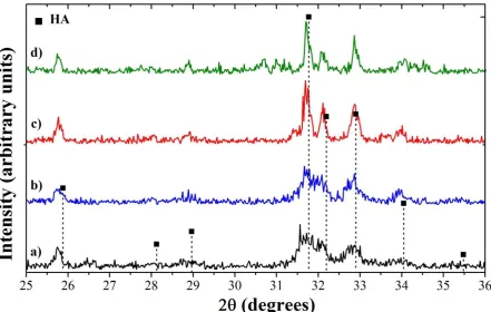
Figure 3.2: XRD patterns of preliminary samples (a) AP01, (b) AP02, (c) AP03, and (d) AP04 produced by AP ... 81
Figure 3.3: XRD patterns of preliminary samples (a) SS01, (b) SS02, (c) SS03, and (d) SS04 produced by SS ... 81
Figure 3.4: XRD patterns of preliminary samples (a) U01, (b) U02, (c) U03, and (d) U04 produced by USPCS ... 82
Figure 3.5: XRD patterns of preliminary samples (a) C01, (b) C02, and (c) C03 produced by CSPCS ... 82
ix
Figure 3.7: Typical particle morphology of preliminary samples (a) AP01, (b) AP04,
(c) U01, (d) U04, (e) C01, (f) C03, (g) SS01, and (h) SS04 ... 84
Figure 3.8: Typical (a) globular particles and (b) polygonal agglomerates observed in USPCS samples ... 85
Figure 3.9: Thermal behaviour of AP01 ... 86
Figure 3.10: Thermal behaviour of U01 ... 86
Figure 3.11: Thermal behaviour of C01 ... 87
Figure 3.12: Thermal behaviour of SS01 ... 87
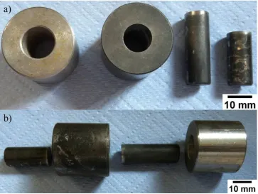
Figure 4.1: Steel die and punch set used to prepare pellets ... 96
Figure 4.2: Preparation of pellets used for in-vitro tests ... 96
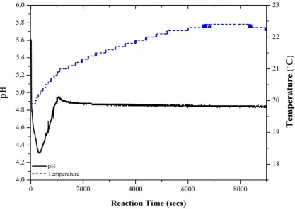
Figure 4.3: Uncontrolled reaction of Ca(NO3)2·4H2O and (NH4)2HPO4 at RT ... 103
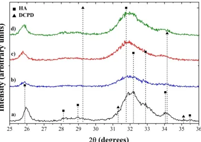
Figure 4.4: Influence of pH value (>10) and control on crystal structure of as-synthesised HA ... 104
Figure 4.5: Influence of solute concentration and temperature on crystal structure of as-synthesised HA (a) AP09, (b) AP11, and (c) AP12... 105
Figure 4.6: Influence of pH on CaP phase formation of as-synthesised (a) AP05, and (b) AP06 ... 105
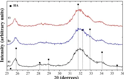
Figure 4.7: Influence of pH on the crystal structure of HA heated to 600°C ... 106
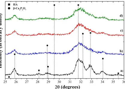
Figure 4.8: Influence of solute concentration and temperature on the crystal structure of HA heated to 600°C (a) AP09, (b) AP11, and (c) AP12 ... 107
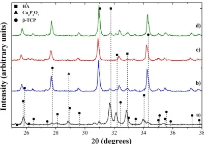
Figure 4.9: XRD patterns of (a) AP07, (b) AP10, (c) AP08, and (d) AP09 heated to 900°C ... 107
Figure 4.10: Influence of pH on FTIR spectra (a) AP07, (b) AP10, (c) AP08, and (d) AP09 ... 109
Figure 4.11: Influence of temperature and solute concentration on FTIR spectra .... 110
Figure 4.12: FTIR spectra of powders heated to 600°C ... 110
Figure 4.13: FTIR spectra of powders heated to 600°C (a) AP09, (b) AP11, and (c) AP12 ... 111
Figure 4.14: FTIR spectra of powders heated to 900°C ... 111
Figure 4.15: Influence of pH, temperature, and solute concentration on typical particle morphology (a) AP05, (b) AP06, (c) AP07, (d) AP08, (e) AP09, (f) AP10, (g) AP11, and (h) AP12... 112
x
Figure 4.17: Thermal behaviour of AP07 ... 114
Figure 4.18: Thermal behaviour of AP09 ... 115
Figure 4.19: Thermal behaviour of AP10 ... 115
Figure 4.20: Thermal behaviour of AP12 ... 116
Figure 4.21: ZP measurements over time for samples AP07 and AP09 in DMEM at 37°C ... 119
Figure 4.22: Pellet surface prior to immersion in SBF visualised by SEM ... 120
Figure 4.23: Surface roughness (Ra) of pellets immersed in SBF for up to 28 days . 120 Figure 4.24: Typical morphology of surface apatite (a) AP10 day 7 (dotted blue circle = apatite layer, dashed red circle = pellet surface), and (b) AP12 day 14 (solid purple circle = needle-like morphology of apatite) ... 121
Figure 4.25: Influence of pH, temperature, and solute concentration on the viability of MC3T3 osteoblast precursor cells seeded on substrates (green = live, red = dead) ... 122
Figure 4.26: Influence of pH, temperature, and solute concentration on the metabolic activity of MC3T3 cells ... 123
Figure 4.27: Proliferation of MC3T3 cells on substrates prepared under different pH, solute concentration, and temperatures assessed by Hoechst assay ... 124
Figure 4.28: Combined bright field and fluorescence images of MC3T3 cells exposed to particle of (a – c) AP07, (d – f) AP08, (g – i) AP09, and (j – l) AP10. Images in columns 1 and 2 are slices from a confocal z stack taken through the middle of the cell, and column 3 at the top of the cell ... 126
Figure 5.1: Influence of solvent system on as-synthesised crystal structure of (a) AP09, (b) AP13, (c) AP14, and (d) AP15 ... 140
Figure 5.2: Influence of solvent system on the crystal structure of samples heated to 600°C ... 140
Figure 5.3: Influence of solvent system on molecular structure of as-synthesised samples ... 141
Figure 5.4: Influence of solvent system on molecular structure of samples heated to 600°C ... 142
Figure 5.5: Influence of solvent system on typical particle morphology ... 142
Figure 5.6: Thermal behaviour of AP13 ... 143
Figure 5.7: Thermal behaviour of AP14 ... 144
Figure 5.8: Thermal behaviour of AP15 ... 144
xi
Figure 5.10: Influence of solvent system on the morphology of surface apatite after SBF immersion (a) AP13 day 7 surface layer, (b) AP14 day 14 needle-like surface
particles, and (c) AP15 day 7 spheroidal surface particles ... 148
Figure 5.11: Influence of solvent system on the viability of MC3T3 cells seeded on substrates (green = live, red = dead) ... 148
Figure 5.12: Influence of solvent system on metabolic activity of MC3T3 osteoblast precursor cells ... 149
Figure 5.13: Proliferation of MC3T3 cells on substrates prepared in different solvent systems assessed by Hoechst assay ... 151
Figure 6.1: Influence of cations on as-synthesised crystal structure of HA ... 163
Figure 6.2: Influence of cations on the crystal structure of samples heated to 600°C ... 163
Figure 6.3: Influence of cations on molecular structure of as-synthesised samples .. 165
Figure 6.4: Influence of cations on the molecular structure of samples heated to 600°C ... 165
Figure 6.5: Influence of cations on typical particle morphology ... 166
Figure 6.6: Thermal behaviour of AP16 (Sr) ... 167
Figure 6.7: Thermal behaviour of AP17 (Mg) ... 167
Figure 6.8: Thermal behaviour of AP18 (Zn) ... 168
Figure 6.9: Surface of pellets containing cations prior to immersion in SBF ... 170
Figure 6.10: Influence of cations on the morphology of surface apatite grown in SBF (a) AP16 day 7, (b) AP18 day 14, and (c) AP16 day 28 (solid blue circle pellet surface, dashed red circle surface coating) ... 170
Figure 6.11: Influence of cations on the viability of MC3T3 cells seeded on substrates (green = live, red = dead) ... 171
Figure 6.12: Influence of cations on metabolic activity of MC3T3 osteoblast precursor cells ... 172
Figure 6.13: Proliferation of MC3T3 cells on substrates substituted with divalent cations assessed by Hoechst assay ... 173
Figure 7.1: CAD design of 3DP cylindrical scaffolds (1mm pores, 10mm height and diameter) ... 184
Figure 7.2: XRD pattern of (a) supplied HA, (b) 50HA:50PVOH, and (c) HA sintered to 1300°C ... 185
xii
Figure 7.4: Thermal behaviour of ball milled PVOH used in the 3DP process ... 187
Figure 7.5: Thermal behaviour of Y02 25wt% HA bioceramic dough formed in YP process ... 188
Figure 7.6: Micrographs of scaffolds produced via YP method and sintered at 1300°C ... 189
Figure 7.7: Influence of DAY content on average pore size of YP scaffolds ... 190
Figure 7.8: Influence of HA loading on the development of pores within YP scaffolds ... 191
Figure 7.9: Typical 3D distribution of pores in YP constructs ... 191
Figure 7.10: Stability of 3D printed blocks ... 192
Figure 7.11: Surface topography of 3D printed blocks (a – c) 50wt% HA 100% saturation, (d – f) 70wt% HA 194% saturation, and (g – i) 80wt% HA 194% saturation ... 193
Figure 7.12: 50wt% HA green scaffolds produced via 3DP ... 194
Figure 8.1: Measurements to calculate angle of repose (R) ... 202
Figure 8.2: Measurements to assess the spreadability of composite powders... 204
Figure 8.3: Set up of compressed air method to de-powder scaffolds ... 205
Figure 8.4: Compressive strength testing set-up (a) positioning of sample within loading cell, and (b) adjustment of loading cell ... 206
Figure 8.5: Funnel test results for HA:PVOH precursor powders (n=3) ... 208
Figure 8.6: Particle size analysis of HA:PVOH precursor powders (ratios expressed as wt%) ... 209
Figure 8.7: Bulk and tapped density of HA:PVOH precursor powders ... 210
Figure 8.8: Illustration of typical powder distributions for 50wt% HA (a) powder and build beds, (b) powder bed topography, (c) comparison of powder and build bed topographies, and (d) build bed topography ... 211
Figure 8.9: Build to powder bed ratios of HA:PVOH precursors ... 212
Figure 8.10: Typical clumping behaviour of 60wt% HA precursor (a) powder bed, (b) close up of powder bed, and (c) build bed ... 212
Figure 8.11: Typical micrographs of (a - b) HA, (c - d) 50HA:50PVOH, and (e - f) PVOH precursors... 213
Figure 8.12: FTIR spectra of HA and PVOH raw materials ... 214
xiii
Figure 8.14: Thermal behaviour of HA:PVOH precursors ... 216
Figure 8.15: Average amount of powder removed from 50wt% HA green scaffolds using ultrasound (n=3) ... 217
Figure 8.16: Effectiveness of ultrasound treatment to remove loose powder from 50wt% HA green bodies ... 217
Figure 8.17: Effectiveness of compressed air to de-powder 50wt% HA green bodies (a) printed scaffold, (b) side view of powdered scaffold, and (c) top view of
de-powdered scaffold ... 218
Figure 8.18: Dried 50wt% HA green scaffolds ... 220
Figure 8.19: Influence of post-processing on size of 50wt% HA green body scaffolds ... 221
Figure 8.20: Influence of post-processing on weight of 50wt% HA green body scaffolds ... 221
Figure 8.21: Influence of drying methods on composition of X-axis 50wt% HA green bodies ... 222
Figure 8.22: Influence of post-processing methods on the height of designed pore channels of 3D printed green scaffolds ... 223
Figure 8.23: Influence of post-processing methods on strut width of 3D printed green scaffolds (significant difference observed compared with: *50PX, **50PY, #60PX,
and ##60PY) ... 223
Figure 8.24: Influence of post-processing methods on average surface pore size of 3D printed green scaffolds (significant difference observed compared with: *50PX,
**50PY, #60PX, and ##60PY) ... 224
Figure 8.25: Micrographs of 50wt% HA green scaffolds printed along X-axis ... 226
Figure 8.26: Average compressive yield strength of 50 and 60wt% HA 3D printed green scaffolds (n= 3) ... 227
Figure 8.27: Average ultimate compressive strength of 50 and 60wt% HA green scaffolds (n= 3) ... 228
Figure 8.28: Average strain at onset of plastic deformation in 3D printed 50 and 60wt% HA green scaffolds under compressive loading (n= 3) ... 229
Figure 8.29: Average compressive strain of 3D printed 50 and 60wt% green scaffolds at failure (n= 3) ... 229
xiv
Figure 8.31: Sintered scaffolds heat treated using HT8 protocol (a) 50PX, (b) 50F2X, (c) 50F6X, (d) 50V2X, (e) 50V6X, (f) 50PY, (g) 50F2Y, (h) 50F6Y, (i) 50V2X, and
(j) 50V6Y... 233
Figure 8.32: FTIR spectrum of 50wt% HA scaffolds printed along X-axis and sintered using HT8 (a) 50wt% HA precursor post TGA analysis, (b) 50PX, (c) 50F2X, (d)
50F6X, (e) 50V2X, and (f) 50V6X ... 234
Figure 8.33: FTIR spectrum of 50wt% HA scaffolds printed along Y-axis and sintered using HT8 (a) 50wt% HA precursor post TGA analysis, (b) 50PY, (c) 50F2Y, (d)
50F6Y, (e) 50V2Y, and (f) 50V6Y ... 235
Figure 8.34: Bulk shrinkage of X-axis 50wt% HA scaffolds sintered using HT8 (n=3) ... 236
Figure 8.35: Bulk shrinkage of Y-axis 50wt% HA scaffolds sintered using HT8 (n=3) ... 236
Figure 8.36: Shrinkage of pore channel height for sintered scaffolds compared with green bodies (n=3) ... 238
Figure 8.37: Shrinkage of strut width for sintered scaffolds compared with green bodies (n=3) ... 238
Figure 8.38: Shrinkage of surface pores for sintered scaffolds compared with green bodies (n=3) ... 239
Figure 8.39: Micrographs of 50wt% HA sintered scaffolds printed along X-axis (a) 50PX pore channel, (b) 50PX strut, (c) 50PX surface, (d) 50F2X pore channel, (e)
50F2X strut, (f) 50F2X surface, (g) 50F6X pore channel, (h) 50F6X strut, (i) 50F6X
surface, (j) 50V2X pore channel, (k) 50V2X strut, (l) 50V2X surface, (m) 50V6X pore
channel, (n) 50V6X strut, and (o) 50V6X surface ... 240
Figure 8.40: Micrographs of 50wt% HA sintered scaffolds printed along Y-axis (a) 50PY pore channel, (b) 50PY strut, (c) 50PY surface, (d) 50F2Y pore channel, (e)
50F2Y strut, (f) 50F2Y surface, (g) 50F6Y pore channel, (h) 50F6Y strut, (i) 50F6Y
surface, (j) 50V2Y pore channel, (k) 50V2Y strut, (l) 50V2Y surface, (m) 50V6Y pore
xv
List of Tables
Table 2.1: Comparative composition and unit cell parameters of bone apatite and stoichiometric HA adapted from [11, 57] ... 37
Table 2.2: Summary of the mechanical properties of human cortical and cancellous bone ... 40
Table 2.3: Summary of current graft types [83-85] ... 41
Table 2.4: Hierarchical pore size distribution of an ideal bone tissue scaffold [99] ... 42
Table 2.5: Summary of biologically relevant CaP [57] ... 45
Table 2.6: Summary of common synthesis methods for synthetic apatite ... 52
Table 2.7: Summary of reaction parameters reported to be influential in the AP of HA ... 56
Table 2.8: Comparison of common conventional and ALM techniques used to fabricate bone tissue scaffolds ... 62
Table 2.9: Comparison of ALM techniques commonly used to fabricate bone tissue scaffolds ... 68
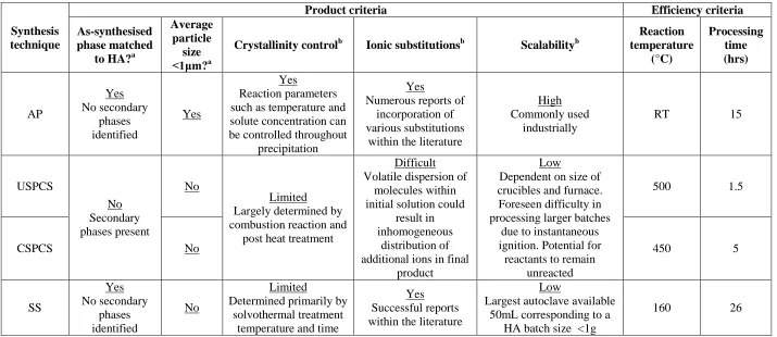
Table 3.1: Selection of synthesis methods to produce HA according to defined product and efficiency criteria ... 76
Table 3.2: Influence of heat treatment with respect to phase and average crystallite size of preliminary samples ... 80
Table 3.3: Summary of the average size and typical morphology of particles observed by SEM ... 83
Table 3.4: TGA analysis of as-synthesised preliminary samples ... 85
Table 3.5: Feasibility of selected HA synthesis methods according to product and efficiency criteria ... 92
Table 4.1: Summary of varied pH, temperature and solute concentration conditions. 95
Table 4.2: Fcrit values for data sets collected for MTT and Hoechst assays ... 102
Table 4.3: Development of solution pH... 103
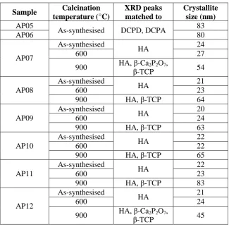
Table 4.4: Influence of pH, temperature, and solute concentration on phase and XRD peak broadening... 108
xvi
Table 4.6: Influence of pH, temperature, and solute concentration on average particle
and agglomerate size (n=3) ... 113
Table 4.7: Summary of DTG analysis ... 114
Table 4.8: Influence of pH, temperature, and solute concentration on the amount of water lost between temperature regions associated with Equations 2.3 – 2.5 ... 116
Table 4.9: Influence of pH, temperature, and solute concentration on chemical composition calculated from DTG analysis using Equations 2.3 – 2.5 ... 117
Table 4.10: Infleunce of pH on Ca:P ratio calculated from EDS and XRF analysis . 118 Table 4.11: Influence of pH, temperature and solute concentration on the surface area of as-synthesised powders ... 118
Table 4.12: Influence of pH, temperature, and solute concentration on ZP of as-synthesised particles measured in DI water at 25°C ... 119
Table 4.13: Influence of pH, temperature, and solute concentration on the proliferative rate of MC3T3 cells assessed by MTT assay between 1 and 7 days ... 123
Table 4.14: Statistical analysis of MTT assay samples AP08 – AP12 ... 124
Table 4.15: Influence of pH, temperature, and solute concentration on the proliferative rate of MC3T3 cells assessed by Hoechst assay between 1 and 7 days ... 125
Table 4.16: Statistical analysis of Hoechst assay ... 125
Table 5.1: Summary of varied solvent conditions ... 138
Table 5.2: Development of solution pH in different solvent systems ... 139
Table 5.3: Influence of solvent system on phase and XRD peak broadening ... 141
Table 5.4: Influence of solvent system on average particle and agglomerate size (n=3) ... 143
Table 5.5: Influence of solvent system on the amount of water lost between temperature regions associated with Equations 2.3 – 2.5 ... 145
Table 5.6: Influence of solvent system on chemical composition calculated from DTG analysis using Equations 2.3 – 2.5... 145
Table 5.7: Influence of solvent system on Ca:P ratio measured by EDS (n=3) ... 145
Table 5.8: Influence of solvent system on the surface area of as-synthesised powders ... 146
Table 5.9: Influence of solvent system on ZP measured in DI water at 25°C ... 146
Table 5.10: Influence of solvent system on the proliferative rate of MC3T3 cells assessed by MTT assay between 1 and 7 days ... 150
xvii
Table 5.12: Influence of solvent system on the proliferative rate of MC3T3 cells
assessed by Hoechst assay between 1 and 7 days ... 151
Table 5.13: Statistical analysis of Hoechst assay AP13 – AP15 ... 151
Table 6.1: Summary of divalent cation substitutions ... 161
Table 6.2: Development of solution pH containing additional divalent cations ... 162
Table 6.3: Influence of cations on phase and XRD peak broadening... 164
Table 6.4: Influence of cations on the position of characteristic XRD peaks compared with AP09 and HA reference pattern (09-432) ... 164
Table 6.5: Influence of cations on the average particle and agglomerate sizes (n=3)166 Table 6.6: Influence of cations on the amount of water lost between temperature regions associated with Equations 2.4 and 2.5 ... 168
Table 6.7: Influence of cations on chemical composition calculated from DTG analysis using Equations 2.4 and 2.5 ... 168
Table 6.8: Accuracy of cation substitution levels measured by XRF ... 169
Table 6.9: Influence of cation substitutions on the surface area of as-synthesised powders... 169
Table 6.10: Influence of cations on the proliferative rate of MC3T3 cells assessed by MTT assay between 1 and 7 days ... 172
Table 6.11: Statistical analysis of MTT assay AP16 – AP18 ... 172
Table 6.12: Influence of cations on the proliferative rate of MC3T3 cells assessed by Hoechst assay between 1 and 7 days of culture ... 173
Table 6.13: Statistical analysis of Hoechst assay AP16 – AP18 ... 174
Table 7.1: Summary of the reaction conditions used to fabricate scaffold structures via YP method (G = ground, UG = unground) ... 183
Table 7.2: Summary of the average pore size of YP scaffolds (n=3) ... 190
Table 7.3: Reproducibility of 50wt% HA scaffolds produced via 3DP (n=6) ... 194
Table 8.1: Flowability of HA:PVOH precursor powders using funnel tests (n=3) ... 208
Table 8.2: Particle size percentiles of HA:PVOH precursor powders ... 209
Table 8.3: Change in density due to ultrasound treatment ... 210
Table 8.4: Summary of typical microstructure observed for HA, 50HA:50PVOH, . 214 Table 8.5: Summary of weight loss behaviour for HA:PVOH precursors ... 216
Table 8.6: Printability of scaffold structures fabricated from HA:PVOH precursor powders... 216
xviii
Table 8.8: Effect of drying processes on the microstructure of 3D printed green scaffolds (n=6) ... 225
Table 8.9: Heat treatment protocols employed on 50wt% HA scaffolds ... 232
xix
Acknowledgements
I would like to thank my supervisor Dr Kajal Mallick for his support throughout this
project and his confidence in my ability. I also must acknowledge and extend my gratitude
to Professors Richard Walton and Liam Grover, Dr Greg Gibbons, Dr Stuart Coles and Dr
Ben Douglas for the facilities they so kindly provided as well as their invaluable comments
and feedback that helped to direct this work. Further thanks to Tom Skelhon and Adam
Morgan for assistance with particle size, zeta potential and surface area measurements.
Richard Williams is also recognised for his help with the cellular internalisation
experiments. The University of Warwick Chancellor’s Scholarship is acknowledged for
funding this project.
Special recognitions must be made to Martin Davis and Parastoo Jamashidi. Martin has on
so many occasions been the person I went to when I did not know where else to go and has
always gone that extra mile to help me, which I am truly grateful for. Paras and I went on a
journey to complete and understand the reported cell work. Throughout she offered me
unrivalled professional support and a compassionate ear, thank you Paras.
I would also like to extend my appreciation to Dr James Meredith who has offered me
support throughout this project, invaluable careers advice and helped me organise an
internship with Ceram. Thanks to Dr Phil Jackson and Ben McCarthy at Ceram for
formulating such a challenging and enriching placement that has been an instrumental part
of my career to date.
Personally, I would like to thank all of my colleagues in room 359, close friends, and
Warwick Judo who have supported me throughout this time, offered me ‘proactive’
procrastination and kept a smile on my face.
Mum, Dad, Sam and Sami, thank you for giving me the belief, guidance and love that I
have needed. And of course, Thomas, you’re the best and Squidger would not be where she
xx
Declaration
This thesis is the original work of the author and is submitted to fulfil the requirements of
the degree of Doctor of Philosophy (PhD). The research was performed at WMG of the
University of Warwick and the School of Chemical Engineering of the University of
Birmingham between October 2010 and September 2013, under the supervision of Dr
Kajal Mallick. This thesis has not been submitted in whole or in part as consideration for
any other degree qualification at this or any other university. Where other work has been
used it has been acknowledged. In accordance with the Degree Committee of the Faculty
of Sciences, the length of this thesis is less than 70,000 words.
Sophie Constance Cox
WMG
University of Warwick
xxi
Publications
Journal articles:
Cox, S. C., Jamshidi, P., Grover, L. M., and Mallick, K. K., “Preparation and characterisation of nanophase Sr, Mg, and Zn substituted hydroxyapatite by aqueous precipitation”, J Maters Sci and Eng Part C, 2013
Cox, S. C., Jamshidi, P., Grover, L. M., and Mallick, K. K., “Low temperature aqueous precipitation of needle-like nanophase hydroxyapatite”, J of Maters Sci: Maters in Med, 2013
Conference proceedings:
Cox, S. C. and Mallick, K. K., “Preparation of nanophase hydroxyapatite via self-propagating high temperature synthesis”, Ceramic Transaction Book Series, Ed: Roger Narayan, Wiley-VCH, 2012
Cox, S. C. and Mallick, K. K.: “Preparation of porous hydroxyapatite scaffolds using yeast as a pore forming agent”, Ceramic Transaction Book Series, Ed: Roger Narayan, Wiley-VCH, 2011
Book chapters (peer reviewed):
Mallick, K. K. and Cox, S. C., “Biomaterial Scaffolds for Tissue Engineering”, Frontiers of Bioscience, Special Edition: Next Generation Biomaterials,
Encyclopaedia of Bioscience, Ed: Roger Narayan, 2011
Oral presentations (peer reviewed):
MiMe International Conference, Oct 2013, Italy
Materials and Manufacturing Annual Conference, WMG, May 2013, UK
Annual Conference, UK Society of Biomaterials, June 2012, UK
MS&T 2011 Conference, American Ceramic Society, October 2011, USA
MS&T 2010 Conference, American Ceramic Society, October 2010, USA
Poster presentations (peer reviewed):
MC11, Royal Society of Chemistry, July 2013, UK
Annual Conference UK Society of Biomaterials, June 2013, UK
World Biomaterials Congress, June 2012, China
Materials and Manufacturing Annual Conference, WMG, April 2012, UK
Annual Conference, UK Society of Biomaterials, 2011, UK
White paper:
xxii
Abstract
It is known that chemical and physical features of bone contribute to its functionality, reactivity and mechanical performance. This knowledge is the fundamental rationale for this project. The aim of this thesis is to study the influence of synthesis conditions on material composition and ultimately the biological performance of hydroxyapatite (HA) as well as to fabricate scaffold structures that physically emulate bone tissue. Concurrent characterisation of physiochemical properties and evaluations of in-vitro cytocompatibility, and the degree of osteoblast proliferation on CDHA substrates precipitated under different reaction conditions provides a novel contribution.
Non-viability of cells seeded on substrates prepared in a solution adjusted to pH 10 (AP07) was confirmed after 1 day of culture. Dead cells were also observed after 3 days on CDHA prepared at 70°C under a controlled pH level of 11 (AP12). XRD found no discernible difference between these samples and CDHA substrates shown to be cytocompatible. The source of cytotoxicity was concluded to be the presence acidic DCPD in AP07, and positive surface charges for AP07 and AP12 that were revealed by FTIR, DTA-TGA and ZP measurements. Control of pH, increased solute concentration, the use of Toluene, and substitutions of 10mol% Mg or 2mol% Zn were shown to enhance the proliferative rate of cells seeded on CDHA synthesised at RT. CDHA prepared in a 60 Toluene: 40 DI water (% v/v) solvent system with a lower dielectric constant (AP14) exhibited marked XRD peak broadening and 20% larger surface area compared with CDHA prepared in DI water (AP09). These features are suggested to explain the enhanced proliferation of cells on AP14, which was shown to be more than double the fluorescence exhibited for AP09 after 7 days. XRF was used to confirm the presence of Sr, Mg, and Zn that were selected due to their key biological roles in bone apatite. Evidence of lattice incorporation of these divalent cations was supported by XRD analysis that demonstrated shifts of characteristic HA peaks. Mg ions inhibited the crystallisation process, which caused a 45% reduction in the crystallite size, 60% increase in particle surface area and thermal conversion to whitlockite at 600°C. The relatively low crystallinity and larger surface area of Mg and Zn doped substrates is proposed to explain the respective 80 and 40% increase in cell proliferation compared to a pure sample prepared under the same conditions. Flowability of HA:PVOH precursor materials correlated well with the mechanical stability, microstructure and porosity of 3D printed scaffolds. Anisotropic behaviour of constructs and part failure at the boundaries of interlayer bonds was highlighted by compressive strength testing. A trade-off between the ability to facilitate removal of PVOH thermal degradation products during sintering and the compressive strength of green parts was revealed. The maximum green scaffold strength of 0.85MPa was exhibited by parts that were air or vacuum dried for 6hrs. Critically, the pores of 3D printed constructs could be user designed ensuring interconnectivity and the imperfect packing efficiency of precursor powders created an inherent surface roughness and microporosity within scaffold struts. These features are known to be favourable for osteogenesis, osteoconduction and osteointegration in-vivo.
xxiii
List of abbreviations
3DP 3D printing
ALM Additive layer manufacturing
ALP Alkaline phosphatase
ANOVA Analysis of variance
AP Aqueous precipitation
BET Brunauer–Emmett–Teller
BG Bone graft
CAD Computer aided design
CAM Computer aided manufacture
CaP Calcium phosphate
CDHA Calcium deficient hydroxyapatite
CHA Carbonated hydroxyapatite
CSPCS Citric acid self-propagating combustion synthesis
CT Computer tomography
DAY Dried active yeast
DCPA Dicalcium phosphate anhydrate (monetite)
DCPD Dicalcium phosphate dihydrate (brushite)
DI Deionised
DMEM Dulbecco’s modified eagle medium
DTA Differential thermal analysis
DTG Differentiated thermogravimetry
EDS Energy dispersive spectroscopy
FDA Food and drug association
FDM Fused deposition modelling
FTIR Fourier transform infrared spectroscopy
HA Hydroxyapatite
hrs Hours
IR Infrared
JCPDS Joint committee on powder diffraction standards
M Mega (=106)
xxiv mins Minutes
MRI Magnetic resonance imaging
MTT 3-(4,5-Dimethylthiazol-2-yl)-2,5-diphenyltetrazolium bromide
n Nano (=10-9)
NMR Nuclear magnetic resonance
OA Osteoarthritis
OP Osteoporosis
PBS Phosphate buffered saline
PVOH Polyvinyl alcohol
Rpm Revolutions per minute
RT Room temperature
s Seconds
SBF Simulated body fluid
SEM Scanning electron microscopy
SLA Stereolithography
SLS Selective laser sintering
SPCS Self-propagating combustion synthesis
SS Solvothermal synthesis
TCP Tricalcium phosphate
TEM Transmission electron microscopy
TGA Thermogravimetry analysis
TP Tissue culture plastic
TTCP Tetracalcium phosphate
USPCS Urea self-propagating combustion synthesis
UV Ultraviolet
XPS X-ray photoelectron spectroscopy
XRD X-ray diffraction
XRF X-ray fluorescence
YP Yeast as a pore forming agent
Chapter 1
26
1.
Introduction
There is an increasing clinical demand to repair and/or regenerate bone defects since
millions of people worldwide are diagnosed with numerous diseases, genetic
abnormalities or endure traumatic injuries that compromise or fall outside of the
self-healing capacity of this hard tissue. Traditionally bone grafts (BGs), most commonly
autografts, have been used to fill or heal such defects. Despite being the ‘gold
standard’ there are several disadvantages of autologous BGs, including painful
harvesting surgery, limited supply, and long recovery times. These short-comings have
driven the research community to investigate alternative solutions that incorporate the
use of synthetic biomaterials.
Specifically, an alternative strategy to traditional BGs is to create a temporary
surrogate structure, which guides and encourages tissue regeneration. In order for such
a strategy to be successful it is necessary to combine expertise of cells, biochemical
factors, and biomaterial science. This interdisciplinary field of research is known as
tissue engineering and the structural component of this strategy, referred to as a
‘scaffold’ is the focus of this project.
Ideally, scaffolds should emulate the chemical and physical structure of the native
tissue, thus it is crucial that an understanding of the properties that infer the
functionality of bone is developed. Bone is an inorganic-organic biocomposite that
largely comprises of nanosized non-stoichiometric carbonated multi-ion substituted
apatite particles incorporated in a collagen matrix. These phases deduce the
compressive strength and stiffness, as well as the elasticity and fracture toughness of
bone, respectively. It is important to note that the porous interconnected 3D structure
exhibited by cancellous bone enables mass transfer of nutrients, vascularisation, and
migration of bone cells.
Much attention has been given to calcium phosphate (CaP) based biomaterials since
generally they are chemically similar to bone apatite. In particular, hydroxyapatite
(HA) has been shown to exhibit a comparable crystal structure and is an FDA
approved CaP [1-4]. However, this material is known to exhibit poor bioresorbability
and bioactivity compared to natural bone mineral due to the high stability of synthetic
27 occur in bone and the use of nanosized HA (nHA) have been shown to enhance the
solubility, bioactivity and response of bone cells to this synthetic material in-vitro and
in-vivo [8-11]. Much effort has been focused on the synthesis of this bioceramic due
to the potential applications of HA as a bone replacement material [12-17]. However,
the majority of such studies are restricted to the preparation and structural
investigation of HA without an evaluation of biological performance [18].
Numerous authors have reported the fabrication of pure or composite HA scaffold
structures using a variety of techniques [19-23]. In recent decades focus has been
directed to the use of additive layer manufacturing (ALM) systems to manufacture
such constructs since they can be user defined, which inherently improves
reproducibility and enables the creation of patient-specific products. It is relatively
common that commercially purchased HA is used as a precursor material and as such
the motivation of such studies is narrowed to the influence of physical attributes. That
is despite the fact that the reactivity of bone mineral is largely determined by its
composition and crystal structure, which is determined by the synthesis method and
reaction conditions [2].
This thesis focuses on understanding the effect of both the synthesis technique and
reaction conditions on characteristic material properties of HA, including crystallinity,
surface charge, chemical composition, and thermal behaviour. Novelty and
contribution to knowledge is gained through relating any observed physical, chemical,
or crystallographic changes with the results of acellular and cellular in-vitro tests. An
investigation of the potential to fabricate scaffold structures suitable for use in the
repair and replacement of cancellous bone by 3D printing (3DP) is also presented.
This section serves as a basis for future work that aims to ‘optimise’ the scaffold by
combining enhanced self-synthesised HA and 3DP.
Objectives
1) To experimentally assess the feasibility of selected synthesis techniques to produce
nHA
2) To synthesise nHA using the selected methodology under various conditions
3) To characterise the physiochemical properties of the synthesised HA, assess the
28 4) To experimentally assess the feasibility of selected fabrication techniques to
construct a scaffold structure that mimics the physical properties of cancellous bone
5) To recommend ‘optimised’ synthesis conditions for future bulk production of nHA
to use in combination with the selected fabrication process
Thesis outline
The introduction in Chapter 1 provides a summary of the research background and
presents the objectives as well as outline of this thesis. Relevant background literature
is discussed in Chapter 2, which has been divided into three parts concerning the
structure of bone, calcium phosphates (CaPs), and scaffold fabrication techniques to
reflect the organisation of the experimental chapters and project objectives. Attention
is focussed on bone mineral, pure as well as substituted HA, synthesis of HA via
aqueous precipitation, and 3DP of bone tissue scaffolds.
Chapter 3 presents a feasibility study to determine the most appropriate synthesis
technique and the conclusions drawn set the foundations for further experimental
work. Chapters 4 – 6 focus on the synthesis of HA via aqueous precipitation.
Specifically the influence of pH, temperature and solute concentration were assessed
in Chapter 4. Chapter 5 presents an investigation of the effects of different solvent
systems, namely containing Toluene and/or Ethanolamine in combination with DI
water, on the physiochemical properties of HA. In an effort to emulate natural bone
mineral more closely substitution of Sr, Mg, and Zn into HA was explored in Chapter
6. Acellular and cellular in-vitro tests were performed on HA prepared under the
various conditions reported in Chapters 4 – 6.
From Chapter 7 onwards the research is focused on the fabrication of HA bone tissue
scaffolds. Initially the viability of producing appropriate structures via a novel
non-aqueous salt leaching technique utilising yeast as a natural pore forming agent was
compared with a promising ALM method, namely 3DP. Chapter 8 extends the 3DP
method introduced in Chapter 7 and a more detailed characterisation of the scaffold
properties is presented, including compressive strength.
The overall project conclusions and recommended future work are discussed in
Chapter 2
30
2.
Literature review
Literature reviewed in this thesis has been split into three parts for clarity and to reflect
the structure as well as rationale of this project. Part one provides the clinical
perspectives of bone as a hard tissue, covering: the clinical need for bone replacement
or repair strategies, common bone diseases and defects, the physical, chemical as well
as crystallographic structure of bone, and clinical solutions. In summary, this section
describes the clinical motivation of this thesis. Literature presented in parts two and
three contain background information as well as scientific rationale for the
experimental chapters. Specifically, part two summarises key aspects of the group of
materials used in this project, CaPs. Sub sections include: HA, synthesis methods, and
the thermal behaviour of CaPs. Finally, part three presents selected literature
concerning the fabrication of bone tissue scaffolds, which encompasses a discussion of
common conventional and ALM methods used to manufacture CaP constructs.
Part one - clinical perspectives of bone
as a hard tissue
2.1 Clinical need
Bones perform several vital functions within the body, primarily structural support and
protection of bodily organs. The ability of bone to self-repair and remodel to meet
different mechanical demands makes it a unique structural composite material [24,
25]. Bone also serves as an: attachment site for muscles to enable limb movement and
joint mobility, a reservoir for minerals (e.g. calcium and phosphorous), and the
primary site for the synthesis of blood cells.
The capacity of bone to function healthily can be affected by pathological conditions,
diseases, and it is also well known that bone degenerates with age [26]. Furthermore,
the ability of bone to self-repair is limited by what is known as the ‘critical size
defect’, defined by Schmitz and Hollinger as “the smallest intraosseous wound in a
31 lifetime of the animal” [27]. The ‘critical’ size is dependent on a number of patient
specific properties such as age, bone health and defect location. This makes it difficult
to comprehensively define an explicit ‘critical’ size. It has been proposed that defects ≥1cm in length and ≥50% of the diameter of the dense outer bone layer (i.e. cortical
bone diameter) can be deemed critical [28].
Major alterations in bone structure due to injury or disease can lead to discomfort and
a reduced quality of life [29], and defects outside of the limitations of natural
self-repair may require surgical intervention, thus creating a demand for appropriate
clinical strategies. However, due to the highly organised and complex structure of
bone this clinical need presents an on-going medical challenge.
2.2 Bone diseases and defects
Millions of people in the UK are affected by bone tissue related diseases, such as
osteoporosis (OP) or osteoarthritis (OA). Cancerous primary and metastasised bone
tumours can also occur but are less common with only 500 cases reported in 2011 [30,
31]. Furthermore, osteomyelitis, infection of bone or bone marrow can lead to
significant tissue destruction. This bacterium or more rarely fungus, most commonly
originates from a skin wound or a bone fracture site. In chronic cases tissue necrosis
may occur, which requires removal and replacement. An average of 7,000 adults are
treated in the UK each year for osteomyelitis [31].
Complex interactions between genetic and environmental factors throughout the
lifespan of bones causes them to age and after the fourth decade of life this is
accompanied by a substantial loss of matter [32, 33]. There are a number of factors
involved in these age related changes, including: imbalance between resorption and
formation of bone, adjustments in architecture, accumulation of microfractures,
localised inconsistency in the concentration of deposited minerals, and changes in
bone tissue mineral deposits as well as protein content [34]. As a result, the
mechanical integrity and resistance of bone to bending stress is compromised making
them more susceptible to fracture [35, 36]. Occasionally, these changes can progress
to a stage where they significantly affect normal functioning.
OP and OA are the most common chronic degenerative bone diseases and the leading
32 3 and 10 million people in the UK are affected by OP and OA, respectively [31, 39].
OP is characterised by low bone mass and micro-architectural deterioration of bone
tissue, leading to enhanced bone fragility and as a consequence increased risk of
fracture [40]. OA can be defined as a heterogeneous group of conditions that lead to
joint symptoms and signs, which are associated with defective integrity of articular
cartilage relating to changes in the underlying bone at the joint margins [41].
The capacity of bone to heal may be compromised by the conditions described above
as well as many other diseases and genetic abnormalities. Furthermore, defects caused
by trauma are common and nearly 350,000 bone fractures were reported in the UK
between June 2009 and May 2010 [31]. All of these issues create a clinical need for
bone repair or replacement strategies. Before potential clinical solutions are
considered an understanding of the physical structure, chemical composition, and
crystallographic arrangement of bone must be developed.
2.3 Bone tissue
2.3.1 Physical structure
Bone is a hierarchical composite that exhibits an irregular heterogeneous and
anisotropic structure that comprises different components at a range of length scales
[42]. These can be divided into well-defined domains: macrostructure (>500μm),
microstructure (1 – 500μm), and nanostructure (<100nm – 1μm).
2.3.1.1 Macrostructure
Macroscopically bone is distinguished into cortical, otherwise known as compact, and
cancellous, also referred to as trabecular or spongy bone. Cortical and cancellous bone
can be easily distinguished by their degree of porosity: 4 – 28%, and 40 – 95%,
respectively [43]. The denser structure of cortical bone forms the outer region of all
types of bone, the diaphysis (shaft) of long bones, and flat bones providing protection
and support for the inner regions. In contrast, cancellous bone exhibits macro-sized
pores, filled with bone marrow, which is found in the centre of all bones. The
33
Figure 2.1: Structure of the femur illustrating regions of cortical and cancellous bone [45]
2.3.1.2 Microstructure
Cortical bone is precisely organised into lamellar Haversian systems, otherwise known
as osteons (microscopic cylinders of bone matrix). Osteons are typically 200 – 250μm
in diameter and run roughly parallel to the long axis of bone. At their centre are
Haversian canals, which have a diameter of approximately 50μm and encompass
blood and lymphatic vessels, as well as nerves [46]. Surrounding these canals are
concentric rings of lamellae, a hard intercellular substance made up of mineralised
collagen fibres 3 – 7μm thick [47]. Between the lamellae are spaces, called lacunae,
which contain osteocytes (mature bone cells). Waste products and nutrients are
transported to and from osteocytes by a branching network of microscopic channels,
called canaliculi, which are connected to adjacent lacunae. Osteons communicate by
Volkmann’s canals, that contain blood vessels which join with the vessels in
Haversian canals and this arrangement is shown in Figure 2.2 [48].
In contrast, the structure of cancellous bone is an irregular honeycomb lattice of thin
plates of trabeculae 50 – 400μm thick and the cavities between are filled with bone
marrow. Nutrients are received by blood vessels embedded in the marrow and
osteocytes, osteoclasts (bone resorbing cells), osteoblasts (bone forming cells), and
34
Figure 2.2: Key microscopic features of cortical bone [49]
Figure 2.3: Microstructure of cancellous bone adapted from [50]
2.3.1.3 Nanostructure
At the nanoscale osteons are predominantly composed of collagen fibres 0.2 – 12μm
in diameter, which consist of bundles of collagen fibrils. Collagen consists of arranged
arrays of tropocollagen molecules, typically 300nm long and 1.5nm wide [51]. These
molecules are composed of three left-handed helices of peptides (monomers of
proteins composed of amino acid sequences) known as α-chains, which are bound
together in a right-handed triple helix making up the collagen fibril that exhibits an
average diameter of 100nm. Fibrils themselves are type I and V collagen and display a
35 Found within collagen fibrils in discrete 40nm holes reside bone apatite crystals [53].
These inorganic apatite crystals are in the form of plates or needles and vary in size,
characteristically 40 – 60nm in length, 5 – 25nm in width, and 1.5 – 5nm thickness
[54, 55]. The assembly of collagen molecules and bone apatite is shown schematically
in Figure 2.4.
Figure 2.4: Assembly of collagen and bone apatite crystals [42]
2.3.2 Chemical composition
90wt% of bone comprises of its inorganic and organic components, and the remaining
10wt% is attributed to water. Inorganic bone apatite crystals are 65 – 70wt% of the dry
weight and contribute to the compressive strength as well as modulus, and stiffness of
bone. FTIR and NMR studies have confirmed that bone mineral is a nonstoichiometric
carbonated multi-ion substituted apatite with calcium (Ca) to phosphorus (P) ratio
between 1.37 and 1.87 [51]. The remaining 30 – 35wt% is composed predominantly of
type I collagen (90%) and non-collagenous proteins (e.g. glycoproteins, growth
factors) that bind the inorganic phase to the collagen fibres. The organic phase confers
36
2.3.3 Crystal structure and composition of bone apatite
A vast group of ionocovalent compounds, called apatites, are represented by the
general formula Me10(XO4)6Y2, where Me is a bivalent ion, XO4 a trivalent ion, and Y a monovalent ion [2]. Bone mineral can be described as a non-stoichiometric apatite
that exhibits a similar crystal structure to hydroxyapatite [Ca10(PO4)6(OH)2 – HA].
Figure 2.5 illustrates the crystal structure of HA that exhibits a hexagonal
arrangement. Two ion channels (3Å diameter) run parallel to the c axis [17]. The first
is filled with Ca2+ (Ca(I) site) and the second with OH-. Six Ca2+ (Ca(II) site) and six PO43- tetrahedra are arranged hexagonally around the hydroxide channel. This system enables partial or total replacement of ions, and in bone apatite numerous biologically
relevant ionic substitutions occur (Table 2.1), thus contributing to the typical low
degree of crystallinity. Divalent cations (e.g. Mg2+) and monovalent cations (e.g. K+) can substitute for Ca2+, and anions such as fluoride (F-) or chloride (Cl-) may substitute for OH- groups. Furthermore, some ions such as carbonates can substitute for OH-, PO43- or both, which are referred to as A, B and AB type substitutions, respectively [2]. Therefore an appropriate formula for bone apatite can be expressed as (Ca,
X)10(PO4, CO3, Y)6(OH, Z)2 with X as substituting cations, and Y and Z being the substituting anions, with the indices 10, 6 and 2 changing according to the degree of
stoichiometry [56].
37
Table 2.1: Comparative composition and unit cell parameters of bone apatite and stoichiometric HA adapted from [11, 57]
Composition Bone Bone HA
Calcium (wt %) 34.8 36.6 39.6 Phosphorus (wt %) 15.2 17.1 18.5 Carbonate (wt %) 7.40 4.8 -
Sodium (wt %) 0.90 1.0 - Magnesium (wt %) 0.72 0.6 - Chloride (wt %) 0.13 0.1 - Pyrophosphate (wt %) 0.07 - - Potassium (wt %) 0.03 0.07 - Fluoride (wt %) 0.03 0.1 - Strontium (wt %) - 0.05 -
Zinc (ppm) - 39 -
Chromium (ppm) - 0.33 - Cobalt (ppm) - <0.025 - Manganese (ppm) - 0.17 - Silicon (ppm) - 500 -
a axis (Å) 9.410 - 9.430 c axis (Å) 6.890 - 6.891
X-ray diffraction (XRD) patterns of bone apatite confirm that the lattice arrangement
is consistent with HA standards but peak broadening and intensity vary due to the
difference in crystallite size, crystallinity and ionic substitutions. Figure 2.6 shows
typical XRD patterns of: (a) bone apatite, (b) crystalline HA with nanosized crystals,
and (c) well-crystallised HA. The marked broadening of the characteristic (211),
(112), (300) and (202) peaks in patterns (a) and (b) indicate a small crystallite size and
the large amorphous fraction of bone apatite is signified by the relatively low intensity
above background. When compared with stoichiometric HA (=100), bone apatite
exhibits a crystallinity of 33 – 37 [57].
There are a number of reports in the literature that propose the surface of bone apatite
exhibits a structured hydrated layer [58, 59]. This model is suggested to be responsible
for the high reactivity and ion exchange capacity of biological apatites. Mobile ionic
species are contained within this layer, including non-apatitic environments such as
38
Figure 2.6: XRD patterns of (a) powdered human bone femur, (b) crystalline HA with nanosized crystallites, and (c) well-crystallised HA illustrating the difference in crystal size and crystallinity
between bone apatite and HA [1]
2.4 Cellular functions of bone
Three cells are important in the maintenance and remodelling of bone: (1) osteoblasts
(bone forming cells), (2) osteocytes (mature bone cells), and (3) osteoclasts (bone
resorbing cells). Each is highly specialised, differentiated and generally does not
replicate [51]. Instead less differentiated cells, known as stem cells, control cell
population. Bone stem cells are normally referred to as osteogenic cells and originate
from the mesenchymal bone marrow stromal cell line. Local osteogenic cell
populations are increased when biochemical signalling molecules are stimulated
during bone remodelling and fracture healing. Depending on the vascularity (i.e. the
availability of nutrients and oxygen) of the local environment different differentiation
routes can be undertaken by osteogenic cells. A highly vascularised environment is
required for bone to form since it cannot diffuse oxygen over long distances due to its
dense mineralised structure. Bone relies on an internal vascular network to circulate
vital oxygen and nutrients, which are then diffused over short distances [51]. If a
differentiating osteogenic cell is surrounded by a highly vascularised environment it
39 Osteoblasts are connective tissue cells found at the surface of bone and once enclosed
can be stimulated to proliferate and differentiate into mature osteoblast cells known as
osteocytes, which are derived by a complex change of form and activity. Osteocytes
are involved with the maintenance of local bone, specifically metabolism, and the
exchange of nutrients as well as waste products by blood. In contrast, osteoclasts
perform the opposite function of osteoblasts and are responsible for the majority of
resorption as well as degradation of existing bone. Specific signalling proteins cause
the migration of mononuclear monocytes to resorption sites that may fuse with each
other to establish multi-nucleated macrophages, which differentiate into specialised
osteoclasts [61]. Monocytes and macrophages are involved in bone resorption during
remodelling and fracture repair [62].
2.5 Mechanical properties of bone
Mechanical properties of bone at the macrostructural level vary from one bone to
another as well as within different regions of the same bone [63-65]. This has been
attributed to differences in microstructure [66]. Ageing and diseases can also affect the
mechanical integrity of bone [26]. Table 2.2 provides a summary of the mechanical
properties of human cortical and cancellous bone.
2.6 Clinical solutions
2.6.1 Bone grafts
A bone graft (BG) is the transplantation bone from one location to another and can be
used to fill skeletal defects, bridge joints, or promote union at a site of delayed union,
non-union or fracture [67]. An estimated 2.2 million bone grafting procedures were
undertaken worldwide in 2005 [68]. Due to the ageing of the world population,
increasing life expectancy, and the growing dynamism of life this number is only
40
Table 2.2: Summary of the mechanical properties of human cortical and cancellous bone (F) = Femur, (T) = Tibia, (Fi) = Fibula, (H) = Humerus, (R) = Radius, (U) = Ulna, and orientation
is longitudinal unless otherwise stated
There are four essential elements of bone regeneration: (1) osteogenesis (the ability for
cells to survive transplantation, proliferate and differentiate into bone cells), (2)
osteoinduction (activation and stimulation of host cells), (3) osteoconduction
(facilitation and alignment of blood-vessels), and (4) osteointegration (surface bonding
between host and grafting material). To qualify as a bone graft, the material must
provide at least one of these functions [80]. Table 2.3 summarises the three types of
bone grafts: (1) allogeneic, (2) autologous, and (3) xenogeneic. Autografts, bone taken
from another part of the patient’s body, have been regarded as the ‘gold standard’ for
many years because they provide osteogenic, osteoconductive, and osteoinductive
properties. Hence they are considered the benchmark for other BGs or synthetic
substitutes. However, supply of autologous bone is limited and harvesting is connected
with numerous complications, such as revision surgery and sensory loss. Furthermore,
it has been reported that autografts can fail in clinical practice as osteogenic cellular
elements may not survive transplantation [81].
2.6.2 Tissue engineering
The issues associated with current BGs have created the need for the development of
alternative clinical solutions to replace or repair bone tissue. Tissue engineering is an
Property Cortical bone Cancellous bone Reference
Compressive Modulus
(GPa)
15.2 – 35.3
(15.2-18.1 (F), 17 (F), 11.5 (F, transverse), 25.9-35.3 (T))
0.0011 - 9.8 [63, 70, 71]
Compressive Strength
(MPa)
114.8 – 213
(150.3-209 (F), 158.9-213 (T), 122.6 (Fi), 132.4 (H), 114.8 (U))
0.15 – 22.5
(0.15 – 22.5, 3.36 – 11.36 (F))
[63, 70-73]
Tensile Modulus
(GPa)
11.5 – 29.2
(15.6-19.4 (F), 17 (F), 11.5 (F, transverse), 18.0-29.2 (T), 18.5 (Fi),
17.2 (H), 18.5 (R), 18.4 (U))
- [70, 74]
Tensile Strength
(MPa)
120 – 161
(120 – 161 (F), 140.3-161 (T), 146.1 (Fi), 122.6 (H), 149.1 (R), 148.1 (U))
1.47 - 2.99 [70, 75]
Torsion Modulus
(GPa)
3.17 – 5.0
3.3-5.0 (F), 3.17-3.58 (F) - [70]
Fracture Toughness (MPa m0.5)
1.77 – 14.8
(5.0-6.4 (F), 2.12-4.32 (T), 1.88-14.8 (T), 1.77 (H))
![Figure 2.1: Structure of the femur illustrating regions of cortical and cancellous bone [45]](https://thumb-us.123doks.com/thumbv2/123dok_us/9603082.463462/34.595.186.458.85.301/figure-structure-femur-illustrating-regions-cortical-cancellous-bone.webp)