Abstract— A new technique was developed for the investigation of chatter formation considering the instability of the closed-loop system formed by machine tool structure and metal-cutting process. Machine tool structure indicates the importance of different system components and it’s dominating mode frequencies whereas the metal cutting process indicates the effect of the instability of chip formation-chip serration frequency. The mechanisms of the investigation of chatter explained by the technique were experimentally verified during end milling operation of medium carbon steel (AISI 45) considering the chips and types of discreteness in the form of serrated saw teeth. Experimental investigations have been conducted on the chips and common types of discreteness in the form of serrated saw teeth. Mechanism of formation of these teeth has been studied and the frequency of their formation has been determined. The different modes of the vibrating components of the machine tools have been identified using modal analysis and the vibration responses during cutting conditions have been recorded using an online monitoring system. The vibration signals in frequency domain have been analyzed to identify the chatter frequencies and compared with the chip serration frequency in a wide cutting speed range for different cutting conditions. It has been found that chatter is the outcome of resonance, which occurs in the system when the frequency of secondary or primary serrated teeth formation is approximately equal to or an integer multiple of the ‘prominent mode frequencies’ of the system components.
Index Terms- secondary saw teeth frequency, prominent
mode frequencies, resonance and chatter.
I. NTRODUCTION
Chatter is undesirable due to its adverse effects on the product quality, operation cost, machining accuracy, tool life, machine-tool bearings, and machine-tool life. It is also responsible for reducing output. Other forms of vibration apart from chatter in metal cutting include free vibration and forced vibration. These do not pose any fundamental problems to the machinist because when the sources of the
Manuscript received January 2, 2010. Md. Anayet Ullah Patwari: is with the Department of Manufacturing and Materials Engineering of International Islamic University Malaysia, Faculty of Engineering, 50728, Kuala Lumpur, Malaysia, Phone: 0060163863794, email: [email protected].
AKM Nurul Amin: is with the Department of Manufacturing and Materials Engineering of International Islamic University Malaysia.
W. Faris: is with the Department of Mechanical Engineering of International Islamic University Malaysia.
Sharulhazrin M.S, Hafizzudin I both are with the Department of Manufacturing and Materials Engineering of International Islamic University Malaysia.
problem are identified, they can be eliminated. The main characteristic of machine tool chatter is that it is a self-induced vibration, not caused by external periodic forces. Chatter draws the energy for its maintenance from the cutting operation. Although chatter has been extensively investigated in the past 100 years, it is still very difficult to suppress it in practice. Taylor suggested that element chip formation is responsible for chatter [1], but this proposition was not acceptable since element chip formation occurs at extremely low cutting speed where chatter is almost absent. Kudinov [2] and Shteinberg [3] considered that the periodic effect of built-up-edge (BUE) formation can excite vibration. Kuznetsov [4] also considered that the vibration caused by the unstable and periodically broken BUE is responsible for chatter. However, no serious chatter is also observed in the cutting speed range of BUE formation, chatter generally exists at relatively higher cutting speeds where BUE is absent. Eliasberg [5] considered that the cause of chatter is the formation of a crack in the chip above the tool point which is observed when the cutting process is monitored using a high speed video camera. However, Loladze [6] established that at higher cutting speeds, the chip fully adheres to the tool surface. As such, there cannot be any crack formed at the tool point at those cutting speed ranges, so it cannot be accepted as the physical cause of chatter. Doi [7], Doi and Kato [8], and later Kato [9] concluded based on their experiments on orthogonal cutting on a reasonably flexible work-piece, that chatter was established primarily due to a phase lag of the cutting force with respect to the fluctuation of chip thickness. It was found that force fluctuations lag the vibration movement. It was postulated that due to this lag effect, some energy is left available in each oscillation to maintain the vibration. These ideas were supported by the work of Tashlickii [10]. Experimental works conducted by Amin [11] contradicted the regenerative chatter theory. Amin found that during turning there are ranges of cutting speed where chatter occurred at nearly constant frequencies and vibration marks left from previous cut did not have any influence on the resultant chatter frequency. This is contradictory to the regenerative chatter theory which suggests that chatter marks on the work-piece surface left from previous cut is responsible for chatter formation. Amin et al. [11] and Anayet U Patwari et al [12] found that the root cause of chatter lies in the coincidence of the frequencyof instability of chip formation with one of the natural frequencies of the machine-spindle-tool system components during end milling machining operation.
A New Technique for the Investigation of
Chatter Formation during End Milling of
Medium Carbon Steel (AISI 45)
II. EXPERIMENTALDETAILS
[image:2.595.328.523.50.122.2]Cutting tests were conducted mainly on Vertical Machining Center (VMC ZPS, Model: 1060) powered by a 30 KW motor with a maximum spindle speed of 8000 rpm. Fig. 1 show the experimental setup cutting test conducted on end milling for machining of medium carbon steel (AISI 45). The main thrust of the experiments was on the study of chips and monitoring of vibrations during end milling operations of medium carbon steel.
Figure 1 Experimental set up for end milling operations For studying the chips, scanning electron microscope (SEM), optical microscope was used. For monitoring the vibration a specially designed vibration monitoring system comprising accelerometer, a 16 channel rack, DAQ card were used. Datalog DASY Lab 5.6 was used for signal analysis and processing.
A. Experimental conditions
The investigation of chatter formation for end milling of medium carbon steel (AISI 45) are carried out with the variation of cutting speed and the depth of cut and feed kept constant. In this experiment, a 20 mm diameter tool holder was used with TiN inserts. In this experiment the cutting speed ranges from 175-250 m/min and the depth of cut were 2.5 mm with feed 0.16 mm/tooth.
B. Tool (inserts)
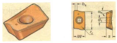
SANDVIK grade PM1030 carbide inserts of code: R390-11 T3 08E-PL was used in the cutting tests. Insert coating material was TiN. Insert geometry is shown in Fig. 2 and Table 1.
Figure 2 Insert Shape and Geometry Table1 Insert Geometry Values L iW d1 s bs rε αnº
11 6.8 2.8 3.59 1.2 0.8 21
III. CHIP ANALYSIS
[image:2.595.315.544.496.673.2]A method for calculating the frequency of instability of chip formation has been developed and the formula for calculating the frequency of instability of chip formation has been derived. The method employed for chip analysis is simple and efficiency, especially in cases where a great number of samples must be examined. The chips are firstly broken and un-twirled to a certain extent. Each segment is then observed under an optical or scan electron microscope to count its respective number of jagged peaks. These are finally added up to get the total number of secondary saw tooth peaks for each chip. In order to have a close look at the chip to identify its morphology and inspect the presence of the primary and/or the secondary serrated teeth and any other type of instability that might be present in the outer view of the chip, the latter was viewed under a scanning electron microscope (SEM). A sample process sequence for the serrated teeth observation under optical microscope and SEM view are shown in Fig. 3, which indicates the presence of the primary and secondary serrated teeth with in the chip body.
Figure 3 Sample process sequence for the serrated teeth observation
The frequency of the primary or secondary serrated teeth formation, Fc, in the cases of milling operation was calculated knowing the length of the portion of the chip in the SEM pictures, L, the coefficient of chip shrinkage, K
chip length), cutting speed, V m/min and the number of serrated teeth, n, observed on the SEM picture; using the following formula: Fc ) ( 60 1000 LK nV
= [Hz] (1)
A. Chip morphology of medium carbon steel
[image:3.595.306.533.72.236.2]The chips during the end milling machining of medium carbon steel are collected for analysis at different cutting conditions. It has been found that chip formation presents extreme cases of secondary chip serration at different cutting conditions.
Figure 4 Chip Morphology: SEM View of chip formed during end milling of medium carbon steel at constant feed: 0.16 mm/tooth and depth of cut 2.5 mm for two different cutting speed (175 m/min and 225 m/min)
The primary serrated teeth are also formed at main body of the chip but it is not so prominent. Typical SEM pictures of chips formed under various cutting conditions are studied and given below in Fig. 4.
IV. CHATTERFORMATIONMECHANISMS The cutting process and the machine tool fixture work system constitute a close loop system. Both the cutting process and the system responses are responsible for the formation of chatter as interacting phenomena. A change in one of the processes can affect the other processes. Though chatter has been investigated by different scientists all over the world but to date it is very difficult to predict the chatter phenomena in machining. The theories proposed before have many limitations and all the phenomena related to chatter can not be explained using those theories.
In the proposed technique all the major parameter having influence on chatter formation has been considered. Chatter is proposed to occur due to resonance between the chip serration frequencies with any prominent mode frequency of the different of machine components (Fig. 5).
[image:3.595.50.282.223.340.2]
Figure 5 Chatter formation Techniques
V. MODALANALYSIS-EXPERIMENTALANDFF ANALYSIS
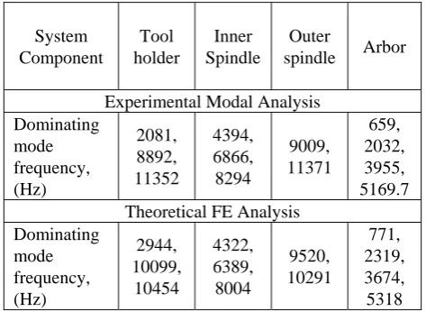
Free vibration analysis of the relevant components of the machine-tool-job-fixture system was conducted for vertical machining centre using experimental modal analysis and finite element modal analysis by ABAQUS software [13].The different dominating mode shape of the different components was extracted and listed in Table 2
Table 2 Mode frequencies of different dominating components of vertical machining centre
It has been observed that the different prominent mode frequency of the different components of the vertical machining centre predicted by FE analysis and experimental modal analysis shows good agreement.
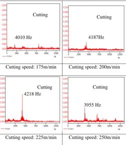
VI. FFTANALYSIS-CUTTINGCONDITIONS The vibration data is recorded and the FFT output in power spectrum for medium carbon steel and the highest vibration peaks and the corresponding excited frequencies at every cutting condition are analyzed. Typical FFT output in power spectrum at various cutting speed with same depth of cut and feed for machining of AISI 45 steel are shown in Fig. 6. From
Hz
2500 5000 7500 10000 12500
Y/t Chart 0 0,225 0,200 0,175 0,150 0,125 0,100 0,075 0,050 0,025 0,000
Cutting Speed, m/min
F req u enc y ( H z) -1
Cutting Speed, m/min
F req u enc y ( H z) Material A V Beating Frequency TOOL CHIP WORK-PIECE Shear Plane Flank Tool face V Shiny Surface Beating Frequency TOOL CHIP WORK-PIECE Shear Plane Flank Tool face V Shiny Surface Hz
2500 5000 7500 10000 12500
Y/t Chart 0 0,225 0,200 0,175 0,150 0,125 0,100 0,075 0,050 0,025 0,000
Cutting Speed, m/min
F req u enc y ( H z) -1
Cutting Speed, m/min
F req u enc y ( H z) Material A V
Cutting Speed, m/min
F req u enc y ( H z) -1
Cutting Speed, m/min
F req u enc y ( H z) Material A V Beating Frequency TOOL CHIP WORK-PIECE Shear Plane Flank Tool face V Shiny Surface Beating Frequency TOOL CHIP WORK-PIECE Shear Plane Flank Tool face V Shiny Surface Beating Frequency TOOL CHIP WORK-PIECE Shear Plane Flank Tool face V Shiny Surface Beating Frequency TOOL CHIP WORK-PIECE Shear Plane Flank Tool face V Shiny Surface System Component Tool holder Inner Spindle Outer
spindle Arbor Experimental Modal Analysis
Dominating mode frequency, (Hz) 2081, 8892, 11352 4394, 6866, 8294 9009, 11371 659, 2032, 3955, 5169.7 Theoretical FE Analysis
[image:3.595.311.548.435.608.2]the power spectrum it has been observed that with the increase of the cutting speed the first mode frequency of the inner spindle (4394 Hz) is excited and the chatter amplitude is going to increase up to the resonance cutting speed and then the amplitude goes down and the next higher mode frequency is going to excite as shown in Fig. 6.
Cutting speed: 175m/min Cutting speed: 200m/min
[image:4.595.315.541.65.197.2]Cutting speed: 225m/min Cutting speed: 250m/min Figure 6 FFT power spectrums during end milling of medium
carbon steel for different cutting speed variation at constant feed: 0.16 mm/tooth and depth of cut 2.5 mm
VII. RELATIONSHIP-CHIPSERRATIONFREQUENCY ANDCHATTERFREQUENCYINENDMILLINGOF
MEDIUMCARBONSTEEL
The secondary serration frequency is more prominent for different cutting speed during end milling of medium carbon steel. The secondary serration frequency for every cutting condition for the given tool holder is calculated and the changes in the frequency of saw teeth formation (chip formation instability) with cutting speed as plotted in Fig. 7. It has been observed that for different cutting speed the chip serration frequency is almost proportional to cutting speed except the horizontal portion of the curve. The horizontal portion of the line indicates the chatter formation zones.
[image:4.595.42.295.135.426.2]It has been also observed that when the frequency of saw tooth formation (chip frequency) approaches the range of the inner spindle (4394 Hz), chatter appears. It has also been observed that the chatter appears in the system when chip serration frequency is close to the inner spindle first mode natural frequency at a speed of 225 m/min as shown in Fig. 7. It is also found that the chip serration frequency is almost constant when it approaches to one of the prominent mode frequencies of the system components and it suddenly goes up after crossing that limits.
Figure: 7 Effect of chip serration frequency on chatter formation (AISI 45) with cutting speed variation
Acceleration amplitude vs. cutting speed is also plotted in Fig. 8. In the inner spindle’s prominent mode frequency range, no severe vibrations are observed below the cutting speed of 200 m/min because the chip frequency is below this natural frequency range, but the amplitude starts to increase and attains the maximum value at 225 m/min because of resonance effect between the secondary chip serration frequencies with the spindle first mode frequency.
Figure: 8 Acceleration amplitude variation with cutting speed
VIII. CONCLUSIONS
Serrated behavior is the outcome of the discrete nature of the chip formation process that exists in the entire cross section of the chip. Serrated edges appear as primary saw/serrated teeth. The machine tool- work-piece-fixture system has various natural mode frequencies, some of which play prominent role in chatter formation. It has been found that the natural frequencies of the inner spindle play prominent role in chatter formation during end milling of medium carbon steel. Chatter or vibration with high amplitude appears in the system during end milling at cutting speed 225 m/min when the frequency of chip formation instability, associated with the formation of secondary serrated/saw teeth, is close to the prominent mode frequency (frequencies) of the spindle at 4394 Hz.
Effect of chip serration on chatter formation
1000 3000 5000 7000 9000
150 175 200 225 250 275
Cutting speed, m/min
F
req
u
en
cy
[
H
z]
Tool diameter 20mm
Spindle first mode frequency
Chatter formation zone
Effect of chip serration on chatter formation
1000 3000 5000 7000 9000
150 175 200 225 250 275
Cutting speed, m/min
F
req
u
en
cy
[
H
z]
Tool diameter 20mm
Spindle first mode frequency
Chatter formation zone
Hz 0 2500 5000 7500 10000 12500
Y/t Chart 0
0,225 0,200 0,175 0,150 0,125 0,100 0,075 0,050 0,025 0,000
Hz 0 2500 5000 7500 10000 12500
Y/t Chart 0
0,225 0,200 0,175 0,150 0,125 0,100 0,075 0,050 0,025 0,000
Hz 0 2500 5000 7500 10000 12500
Y/t Chart 0
0,225 0,200 0,175 0,150 0,125 0,100 0,075 0,050 0,025 0,000
Hz 2500 5000 7500 10000 12500
Y/t Chart 0
0,225 0,200 0,175 0,150 0,125 0,100 0,075 0,050 0,025 0,000
Cutting Cutting
Cutting 4218 Hz
4010 Hz 4187Hz
3955 Hz Cutting
Acceleration amplitude at different cutting speed for medium cabon steel
0 0,05 0,1 0,15 0,2
150 170 190 210 230 250 270
Cutting Speed, m/min
A
c
c
e
le
ra
ti
o
n
A
m
p
lit
u
d
e
[v
[image:4.595.311.547.362.517.2]REFERENCES
[1] Taylor, F.W. 1907. “On the Art of Cutting Metals”. Trans. Amer. Soc. Mech. Eng. 28-30.
[2] Kuznetsov, V.D,1977, “Fizika Rezania e Trenia Metallov e Kristalov (Russian)”, Moscow, Nayka, 310.
[3] Shteinberg, I.C., 1976, “Removal of Chatter Appearing During the Metal Cutting Process on Lathe Machine (in Russian)”, Moscow: Publication of Machine Building.
[4] Kudinov, V.A., 1965, “Dynamics of Machine Tools Moscow (in Russian)”: Publication of Machine Building.
[5] Eliasberg, M.E. 1962, “Fundamentals of the theory of chatter during metal cutting process”, Journal of Machine-Tool. (1): 3-4.
[6] Loladze, T.H. 1980, “Chip Formation During Metal Cutting Process”, Moscow: Publication of Machine Building.
[7] Doi, S., 1953, “On the Chatter Vibrations of Lathe Tools, Memoirs of the Department of Mechanical Engineering”, Nagoya University, 5: 179. [8] Doi, S.& Kato, S., 1953, “Chatter Vibrations of Lathe Tools”, Trans.
Amer. Soc. Mech. Eng. 78: 1073.
[9] Kato, S., 1958, “Theoretical Research on Chatter Vibration of Lathe Tools”, Memoirs of the Department of Mechanical Engineering, Nagoya University, 117.
[10] Tashlickii, N.I.. 1960. “Primary Source of Energy Inducing Self-Oscillations When Cutting Metal (in Russian)”, Vestnik Mashinostroenija.
[11] Amin, A.K.M.N. 1982. Investigation of the Laws Governing the Formation of Chatter during Metal Cutting Processes and their Influence on Tool Wear, Ph.D. thesis, Georgian Polytechnic Institute, Georgia.
[12] Anayet U. Patwari, AKM Nurul Amin, Waleed F Faris, S. Alam; Investigations of the causes of chatter in Computer aided manufacturing process during end milling operation-Proceedings to third international conference on Mechatronics 2008, page 416-421, organized by F a c u l t y o f E n g i n e e r i n g , International Islamic university of Malaysia, 18-20 December 2008.