Irma Slowik1,4, Nils M. Kronenberg2, Markus Franke3,4, Axel Fischer1, Andreas Richter3,4, Malte C. Gather2and Karl Leo1,4
1Institut f¨ur Angewandte Photophysik, Technische Universit¨at Dresden, George-B¨ahr-Strasse 1, D-01069
Dresden, Germany
2SUPA, School of Physics and Astronomy, University of St Andrews, North Haugh, St Andrews KY16 9SS,
Scotland, UK
3Institut f¨ur Halbleiter- und Mikrosystemtechnik, Polymere Mikrosysteme, Technische Universit¨at Dresden,
D-01062 Dresden, Germany
4Center for Advancing Electronics (cfaed), Technische Universit¨at Dresden, D-01062 Dresden, Germany
Tunable optical elements are mostly realized by microelectromechanical systems, which require expensive and complex lithography during processing. We demonstrate an alternative device based on an electrically tunable microcavity employing a dielectric soft elastomer actuator. The cavity resonance is varied by changing the physical cavity thickness due to electrostriction of the soft elastomer. We realize a tunable metal-elastomer-DBR multi-half wavelength microcavity with a cavity layer thickness around 12µm and quality factors up to 700. Applying a voltage up to 60 V between bottom ITO and top metal electrode tunes the wavelength of the cavity modes up to ∆λ= 14 nm, which relates to a cavity thickness change of about 200 nm. This concept allows the implementation of tunable optical elements like tunable filters or resonators with low cost and simple processing.
Electrically tunable optical microcavities are used for versatile applications in the field of sensing, spectroscopy as well as telecommunications1. Particularly for
bio-medical applications or chemical point-of-care analysis, it is desirable to develop simple, compact, and easily processable devices. For this purpose, optical sensing promises high sensitivity and a reduced response time2.
Reconfigurable filters with small bandwidth were re-alized up to now by microelectromechanical systems (MEMS)3,4 which require complicated etching and
lithography or the application of thin membranes as tun-able elements. By comparison, our approach is based on tuning microcavity resonance via an electroactive elas-tomer, is easy and cost-effective. Due to simple design, various structures and scaling to large area arrays are en-visioned.
Dielectric elastomers (DE) are promising materials for electromechanical systems because of their ability to deform reversibly under applied voltage up to very high strains6. Recent applications include artificial
muscles6, loudspeakers7, stretchable integrated circuits8,
and generators9. Due to their high transparency and flexibility, they show high potential to realize tunable optical elements like tunable phase plates10, gratings11,
lenses,12,13 or microcavities4.
Fig. 1 shows the operation principle of a dielectric elas-tomer actuator. When an external voltageV is applied, the elastomer film gets squeezed due to the electrostatic pressure. Pelrine et al.14 demonstrated that in a plate
capacitor set-up, the effective pressurepis written as:
p=ε0εrE2=
ε0εrV2
z2 (1)
where ε0 is the dielectric constant, εr the relative
[image:1.612.338.544.297.361.2]per-mittivity, E the electric field strength and z the thick-ness of the elastomer film. In the simplest model for an unloaded, unconstrained actuator, the thickness strain is
FIG. 1. Operation principle of a dielectric elastomer
actua-tor: (a) A deactivated elastomer film with initial thicknessz0
is sandwiched between two compliant electrodes. (b) Under
applied voltage the elastomer reduces thickness by ∆z and
expands in lateral dimensions.
calculated by Eq. 1 and the elastic modulusY, which is defined as ratio of stressσto strains, so thatσ=Y s. For small strains up to 10%, it can be assumed thatz≈z0,
wherez0 is the initial thickness of the elastomer film15.
Hence, the thickness variation ∆z is described for small strains by:
∆z=ε0εrV
2
Y z0
. (2)
As the dielectric elastomer used in this work is in-compressible, flexible electrodes are essential for the realization of the actuator. Compliant metal electrodes on soft elastomers are rather difficult to achieve due to the large difference in the elastic modulus of the used elastomer (kPa range) and the metal (tens of GPa). Furthermore, rigid substrates influence the actuator performances due to the one-side-constraint of the soft-dielectric film21. Particularly on thin elastomer
films, a metal electrode is expected to have a signifi-cant stiffening impact on the structure. Also, the low elasticity of metals (2-3%)8 hampers the usage of metal electrodes as cracks are formed during stretching of the elastomer film19. Improvements in the elasticity of metal
either in zig-zags15, coils16, or as horseshoe shaped tracks17. An alternative means to keep the stiffening
impact of the metal electrode low but at the same time maintain a closed film with reasonable conductiv-ity, is to reduce the lateral dimension of the metal layer18.
Here, we report on metal-elastomer-DBR microcav-ities as schematically illustrated in Fig. 2 (a). The
ITO electrode Dielectric mirror Metal electrode
Elastomer film
Glass
(b) (a)
FIG. 2. (a) Schematic picture of the sample design of the
elec-trically tunable metal-elastomer-DBR microcavity. A ITO
film on the glass substrate acts as transparent bottom elec-trode. On top a highly reflecting DBR mirror is deposited
with 21 alternating layers of SiO2 and TiO2. The soft
elas-tomer layer acts as tunable cavity layer. Structured metal electrodes are thermally evaporated acting as top electrode and highly reflecting mirror. (b) Transmission spectra of a metal-elastomer-DBR microcavity with a cavity layer
thick-ness of about 15.3µm measured within in the stop band of
the DBR. Fabry-Perot modes are formed with quality fac-tors up to 700 defined by the reflectivity of the DBR and the metal mirror. The blue dashed line depicts the corresponding transmission spectra generated by transfer matrix algorithm.
bottom mirror is formed by a distributed Bragg reflector (DBR) made of 21 alternating layers of SiO2 and TiO2
deposited on a glass substrate with ≈90 nm of indium tin oxide (ITO) layer serving as the bottom electrode. A film of an ultra-soft poly(siloxane) based elastomer (stiffness ≈ 3 kPa) produced by spin coating and heat curing is deposited on the DBR. By variation of the rotation speed, the thickness is adjusted between 3 and 15µm. To increase the surface energy of the elastomer layer, a soft oxygen plasma treatment is performed prior to the physical vapor deposition. The top mirror and electrode is formed by a 25 nm thick silver layer, which is deposited on the elastomer layer by physical vapor deposition. The film thickness used here represents a trade off between good mechanical compliance on the one hand side and high optical reflectance and electrical conductivity. Depending on application, adjustments with better mechanical or optical performance would be possible. Fig. 2 (b) depicts exemplary a transmission spectra of an metal-elastomer-DBR microcavities with a layer thickness of 15 µm. The measured spectra is compared with a simulation by transfer matrix algorithm showing a good agreement between both. A Fabry-Perot cavity is formed between the dielectric bottom mirror and the top metal layer. The width of the peaks depends on quality factor of the cavity and thus on the reflectivity
of both mirrors. The mode position and the distance is defined be the cavity layer thickness. Reducing the optical thickness of the cavity layer leads to a shift of the mode positions to lower wavelengths as well as in a decrease of the free spectral range.
Due to the low surface energy of untreated siloxane elastomers, thermally deposited silver tends to grow in nano-islands, form clusters and microcracks22. Such
non-uniform metal films with high roughness exhibit a lower reflectivity and an enhanced absorption by surface plasmons. To overcome this problem, the elastomer is treated with a soft oxygen plasma prior to the metal deposition which increases the surface energy by increas-ing the number of hydrophilic groups on the polymer surface23. By applying oxygen plasma treatment, we are
able to double the reflectivity of the metal film and thus achieve quality factors for the multi-half wavelength microcavity up to 700 (compare Fig. 2 (b)).
Electrostriction of the metal-elastomer-DBR cavity is tested by optical investigations. Fig. 3 (a) shows confo-cal microscope image of the edge of the metal electrode under monochromatic illumination at 650 nm at vari-ous applied voltages. Differences in optical thickness of the device are visible as interference fringes. Applying a voltage reduces the microcavity thickness and there-fore interference structure. The minimum in the inter-ference pattern at the edge of the electrode changes to a maximum, which refers to a variation of optical thick-ness of λ0\4n ≈ 115 nm. Due to the constraint of
the elastomer on the rigid substrate, the active deforma-tion occurs mainly at the rim of the top metal electrode where the compressed material expands to the metal free area. The variation of the cavity layer thickness leads to a change of the mode spectrum of the microcavity (Fig. 3 (b)). A change in the cavity spectrum under ap-plied voltage is observed by reflection measurements close to the metal edge (Fig. 3 (c)). The quadratic dependence between applied voltage and cavity deformation (com-pare Eq. 2) is confirmed by fitting a simple quadratic function (Fig. 3 (d)).
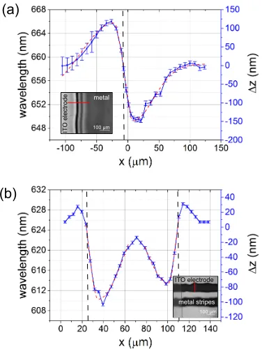
To investigate the spatial distribution of the actuation, cross sections at the metal edge are analysed. Fig. 4 (a) depicts the profile of the actuated sample discussed in Fig. 3. The compression of the cavity underneath the electrode and the expansion outside the electrode area are phenomenologically described with a bi-Gaussian function for each peak (red dashed line). From this, the width of the deformation is estimated to be approxi-mately 50µm.
[image:2.612.65.286.162.251.2](c)
(b) (a)
[image:3.612.84.278.58.432.2](d)
FIG. 3. Optical characterization of the metal-elastomer-DBR
cavity (25 nm Ag, 12µm elastomer): (a) Confocal microscope
image of metal electrode edge under monochromatic illumi-nation at 650 nm for various applied voltages. A change of interference fringes at the rim of the metal film indicates a thickness change at these positions. (b) Simulated transmis-sion spectra of the metal-elastomer-DBR cavity with transfer matrix algorithm shows the shift of mode spectrum depend-ing on the optical thickness of the cavity layer measured in quarter wavelength (qw) for a design wavelength of 630 nm. (c) Reflection spectra measured for different applied voltages. (d) Change in position of a mode located around 633 nm and the decrease in cavity thickness derived from this shift as a function of the applied voltage (black dots). The blue dashed line represents a quadratic fit of the measured data using Eq. 2.
However, the quality factors measured close to the metal edge are much lower than in the reference shown in Fig. 2 (b). This effect occurs because of the shadow mask evaporation not sharp but more trapezoid-like metal edges are formed. Higher quality factors with expense of the tuning range can be achieved with increasing
dis-100 µm
IT
O
e
le
ct
ro
de metal
100 µm ITO electrode
metal stripes (a)
(b)
FIG. 4. (a) Cross section profile of the sample discussed in Fig. 3 shows actuation of metal electrode and the respective mode shift for an applied voltage of 60 V. The edge of the electrode is marked in the profile a with black dashed line. The deformation is fitted with a bi-Gaussian function for each
peak (red dashed line). Inset: confocal microscope image
of sample. The cross section is taken at the red line. (b) For comparison, the profile for a sample with a structured
electrode (stripe width, 90 µm) at the same voltage. The
actuation has to maxima at the edges of the metal stripe resulting in a ’W’-like shape of the deformation.
[image:3.612.343.531.68.318.2]thin-5 6 0 5 8 0 6 0 0 6 2 0 6 4 0
0
1 0 2 0 3 0 4 0 5 0
tr
a
n
s
m
is
s
io
n
i
n
te
n
s
it
y
(
a
.u
)
w a v e l e n g t h ( n m )
[image:4.612.102.254.59.199.2]0 V 5 0 V 7 0 V 8 0 V 9 0 V
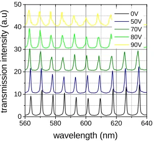
FIG. 5. Transmission spectra for the metal-elastomer-DBR cavity shown in Fig. 4 (a) measured in a microscope setup
with a spot size of about 50µm (objectives: focusing 25x NA
0.5, imaging 50x NA 0.8). The spectra are taken wit a
dis-tance of 50-100 µm to the edge. Under applied voltage the
position of the optical modes is shifted up to 1 nm to lower wavelength because of the compression of the soft elastomer cavity layer. Due to inhomogeneous deformation of the elas-tomer layer, the quality factor decreases from 700 (0 V) to 300 (90 V).
ner cavity layers due to the higher electrical field strength (compare Eq. 2) at a small expense of the quality factor. However, for very thin elastomer layer the activated sur-face layer has an higher impact on the elasticity of the device. Even so, the stiffening impact of the metal layer increases for thinner layers. Therefore, the layer thick-nesses of the different components has to be well chosen depending on the application of the optical cavity regard-ing their optical and mechanical properties.
Alternatively, electrical actuation is proven by capaci-tance measurements (see Fig. 6 (a)). Due to the de-crease of the cavity layer thickness, the capacitance of the device increases. Assuming a plate capacitor set-up (compare Fig. 6 (b)), the capacitance C can be written as:
C0=
0rA
z0
(3)
Capacitance is measured by impedance spectroscopy assuming a simple RC element shown in Fig 6 (c). Since the DBR partly consist of the high-k material of TiO2, the capacitance CDBR ≈500 pF can be neglected
compared to the much lower value of the elastomer layer
C ≈ 10 pF. Inserting Eq. 3 for the cavity thickness deformation results in a quadratic relationship between the applied voltages and the inverse capacitance. For this description, the inhomogeneous deformation of the elastomer layer has to be taken into account. By fitting the profile in Fig. 4 (b) with a bi-Gaussian function, the actual capacitance variation for 60 V is estimated to 1 - 3 fF matching with the result of the electrical measure-ment of 2.2 fF. The capacitance measuremeasure-ments verifies the stability of the electrically tunable microcavity by
R
C
CDBR ~ ~
metal electrode
substrate ITO elastomer DBR
(a) (b)
[image:4.612.329.550.62.194.2](c)
FIG. 6. (a) Averaged capacitance change ∆C under
ap-plied voltage V measured by impedance spectroscopy (f =
100 kHz, Vrms = 200 mV) for 10 cycles. Following Eq. ??
the inverse capacitance follows a quadratic dependence on the applied voltage (blue dashed line). The inset shows the capacitance for 5 sweeps from -40 to 40 V. (b) Schematic view of the measured sample structure; (c) Sample is described as a parallel RC element, while the capacitance of the DBR can be neglected.
more than 100 cycles of reversible actuation.
In conclusion, we have demonstrated an electrically tunable, optical filter realized by a tunable metal-elastomer-DBR multi-half wavelength microcavity employing a thin film dielectric soft elastomer actuator. Applying a voltage between a bottom transparent electrode on the glass substrate and the top metal layer results in a deformation of the soft elastomer. We observed a reversible mode shift of the cavity modes up to 14 nm related to a cavity thickness change of about 200 nm. The electrostriction follows a quadratic voltage behaviour, allowing a control of the resonant wavelength in a range below 1 nm. Larger actuation can be achieved by using elastomers with lower Young’s modulus as cavity layer or altering the metal layer thickness. Furthermore, the performance can be improved using structured electrodes reducing the stiffening impact of the metal eletrode on the soft elastomer layer. Since the devices are fabricated with low cost processing like physical vapor deposition and spin coating, the results offer the possibility to realize cost efficient and simple processable tunable optical elements, e.g. filters, resonators, or display application.
1S. Forget and S. Chenais, “Organic Solid-State Lasers”, Springer Series in Optical Science, Vol. 175, page 165 (2013)
2C. Vannahme, S. Klinkhammer, A. Kolew, P. J. Jakobs, M. Guttmann, S. Dehm, U. Lemmer, and T. Mappes, “Inte-gration of organic semiconductor lasers and single-mode passive waveguides into a PMMA substrate”, Microelectronic Engineer-ing,87, 693-695 (2010)
3M. Pruessner,T. Stievater, and W. Rabinovich, “Reconfigurable filters using mems resonators and integrated optical microcavi-ties”, Proc. of IEEE 21st International Conference on Micro Elec-tro Mechanical Systems, 766-769 (2008)
4W. Chang, A. Wang, A. Murarka, G. M. Akselrod, C. Packard, J. H. Lang, and V. Bulovi´c, “Electrically tunable organic vertical-cavity surface-emitting laser”, Applied Physics Letters, 105, 073303 (2014)
5W. C. Roentgen, “About the Changes in Shape and Volume of Dielectrics Caused by Electricity”, ser. Annual Physics and Chemistry Series11, Sec III, G. Wiedemann, Eds., J. A. Barth Leipzig, Germany 1880, p. 771.
6P. Brochu, and Q. Pei, “Advances in Dielectric Elastomers for Actuators and Artificial Muscles”, Macromolecular Rapid Com-munications,31, 10-36 (2010)
7R. Heydt, R. Kornbluh, J. Eckerle and R. Pelrine, “Sound ra-diation properties of dielectric elastomer electroactive polymer loudspeakers”, Proc. SPIE,6168, 61681M (2006)
8S. Rosset, and H. R. Shea, “Flexible and stretchable electrodes for dielectric elastomer actuators”. Applied Physics A,110, 281-307 (2012)
9R. Pelrine, R. D. Kornbluh, J. Eckerle, P. Jeuck, S. Oh, Q. Pei and S. Stanford, “Dielectric elastomers: generator mode funda-mentals and applications, Proc. SPIE,4329(2001)
10M. Beck, R. Fiolka, and A. Stemmer,“Variable phase retarder made of a dielectric elastomer actuator”, Optics letters,34, 803-5 (2009)
11M. Aschwanden, D. Niederer, and A. Stemmer, “Tunable Trans-mission Gratings based on Dielectric Elastomer Actuators”, Proc. of SPIE,6927, 69271R-1 (2008)
12P. Liebetraut, S. Petsch, W. M”onch, and H. Zappe, “Tunable solid-body elastomer lenses with electromagnetic actuation”, Ap-plied optics,50, 3268-74 (2011)
13C.-C. Huang, D. Liang, W.-P. Shih, and Z.-F. Lin, “Tunable lens driven by dielectric elastomer actuator with ionic electrodes”, Micro & Nano Letters,9, 869-873 (2014)
14R.-E. Pelrine, R. D. Kornbluh, and J. P. Joseph, “Electrostriction of polymer dielectrics with compliant electrodes as a means of actuation”, Sensors and Actuators A: Physical,64, 77-85 (1998) 15R. Pelrine, R. Kornbluh, J. Joseph, R. Heydt, Q. Pei, and S. Chiba, “High-field deformation of elastomeric dielectrics for actuators”, Materials Science and Engineering: C, 11, 89-100 (2000)
16A. Pimpin, Y. Suzuki, N. Kasagi, “Microelectrostrictive Actuator With Large Out-of-Plane Deformation for Flow-Control”, Appli-cation Journal of Microelectromechanical Systems,16, 753-764 (2007)
17M. Gonzalez; F.Axisa, M. V. Bulcke, D. Brosteaux, B. Vande-velde, Bart and J. Vanfleteren “Design of metal interconnects for stretchable electronic circuits”, Microelectronics Reliability, 46(6), 825-832 (2008)
18F. M. Weiss, T. T¨opper, B. Osmani, C. Winterhalter, and C. M¨uller, “Impact of electrode preparation on the bending of asymmetric planar electro-active polymer microstructures”, Smart Structures and Materials,9056, 905607 (2014)
19F. Habrard, J. Patscheider, and G. Kovacs, “Super-compliant metallic electrodes for Electroactive Polymer Actuators”, Proc. of SPIE,8340, 834013 (2012)
20D. Bodas, and C. Khan-Malek, “Hydrophilization and hydropho-bic recovery of PDMS by oxygen plasma and chemical treatment - An SEM investigation”, Sensors and Actuators B: Chemical, 123, 368-373 (2007)
21X. Zhao, and Q. Wang, “Harnessing large deformation and
insta-bilities of soft dielectrics: Theory, experiment, and application”, Applied Physics Reviews,1, 021304 (2014)
22A. Thran, T. Strunskus, V. Zaporojtchenko and F. Faupel, “Ev-idence of noble metal diffusion in polymers at room temperature and its retardation by a chromium barrier, Applied Physics Let-ters,81, 244 (2002)