doi:10.4236/ijcns.2010.33033Published Online March 2010 (http://www.SciRP.org/journal/ijcns/).
On Cross-Layer Design of AMC Based on Rate Compatible
Punctured Turbo Codes
Fotis Foukalas, Evangelos Zervas
Department of Informatics and Telecommunications, University of Athens, Athens, Greece Email:{foukalas, zervas}@di.uoa.gr
Received December 24, 2009; revised January 27, 2010; accepted February 28, 2010
Abstract
This paper extends the work on cross-layer design which combines adaptive modulation and coding at the physical layer and hybrid automatic repeat request protocol at the data link layer. By contrast with previous works on this topic, the present development and the performance analysis as well, is based on rate compati-ble punctured turbo codes. Rate compatibility provides incremental redundancy in transmission of parity bits for error correction at the data link layer. Turbo coding and iterative decoding gives lower packet error rate values in low signal-to-noise ratio regions of the adaptive modulation and coding (AMC) schemes. Thus, the applied cross-layer design results in AMC schemes can achieve better spectral efficiency than convolutional one while it retains the QoS requirements at the application layer. Numerical results in terms of spectral effi-ciency for both turbo and convolutional rate compatible punctured codes are presented. For a more compre-hensive presentation, the performance of rate compatible LDPC is contrasted with turbo case as well as the performance complexity is discussed for each of the above codes.
Keywords:Cross-Layer Design, Adaptive Modulation and Coding, Rate-Compatible Punctured Turbo Codes, Hybrid ARQ, Codes Complexity
1. Introduction
The success of current standard such as 3GPP HSPA and IEEE 802.11/16 in terms of high data rates provision and quality of service (QoS) requirements satisfaction is prin- cipally owed to Adaptive Modulation and Coding (AMC), hybrid automatic repeat-request (HARQ) and fast sched-uling [1,2]. The AMC realization uses different constel-lation orders and coding rates according to the signal strength [3]. By this way, when instantaneous channel conditions are proper, link adaptation offers high data rates at the physical layer. The proper usage of each con-stellation order and coding rate, i.e., mode is specified by the SNR regions in which each separate mode is active.
Enhancement of AMC performance can be achieved by using different channel coding techniques. Particu-larly, in case of turbo-coding implementation, an AMC scheme can achieve the highest spectral efficiency even if low SNR regions are met [4]. The original rate of a turbo code could be 1/3; nevertheless by using punctur-ing techniques greater code rates can be used for each modulated symbol. Incorporating also rate compatibility in punctured turbo codes, by which all of the code
sym-bols of a high rate punctured code are used by the lower rate codes, an enhanced spectral efficiency is reached. This gain is actually provided by Rate-Compatible Punc- tured Turbo (RCPT) codes [5]. RCPT codes have been employed for HARQ implementations due to the fact that no received information is discarded [6]. Such ARQ schemes are well-known as Incremental Redundancy (IR) HARQ schemes that improves the channel use efficiency since parity bits for error correction are transmitted only if this is required [7].
known standards of wireless communications [2,10], we extend this study by employing the aforementioned cross- layer design (CLD) that combines AMC and HARQ based on RCPT codes.
The rest of this paper is organized as follows. Section 2 presents the system model and its components in de-tails. In Section 3, the cross-layer design of the system is presented with its assumptions and constraints. In Sec-tion 4, system performance is evaluated for both turbo and convolutonal rate compatible codes and LDPC as well. Besides, the complexity performance is evaluated for each coded system. Finally, Section 5 provides the concluding remarks and gives some directions for further investigation in this topic.
2. System Model
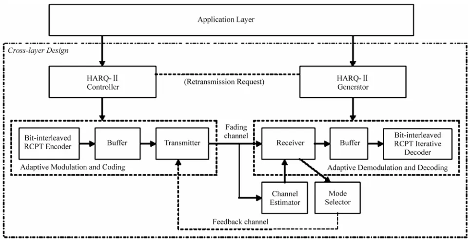
The model of the adopted cross-layer design system is illustrated in Figure 1. It shows the layer structure of the system as well as the implementation details of the AMC scheme (i.e. physical layer). In the following text, we first describe concisely the functionality of each layer and in sequel we go into details for each of layers’ com-ponents.
2.1. Turbo Encoding and Decoding
First, confirm that you have the correct template for your paper size. This template has been tailored for output on the A4 paper size. If you are using US letter-sized paper,
please close this file and download the file for “MSW US ltr format”. Turbo coding and decoding achieves per-formances on error probability near to Shannon limit [11]. In its main form, turbo coding is a channel coding type that combines two simple convolutional codes in parallel linked by an interleaver (i.e. Parallel Concate-nated Convolutional Codes-PCCC) [12]. It had been studied that recursive systematic convolutional codes (RSC) are superior to nonrecursive counterparts for con-catenated implementations [13]. The codewords of such schemes consist of one information bit followed by two parity check bits which both parallel encoders produce. Thus, the rate code of a PCCC scheme with two RSC constituent codes is Rc 1 / 3.
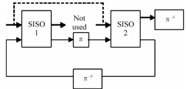
On the other side, the decoding process of concate-nated codes is performed by a suboptimum decoding scheme that uses a posteriori probability (APP) algo-rithms instead of using Viterbi algoalgo-rithms. Such a scheme is constructed by “soft-in/soft-out” decoders that exchange bit-by-bit or symbol-by-symbol APPs as soft information that depends on the bit or symbol decoding technique [14]. The input soft-information represents the log-likelihoods of encoder input bits and code bits. This is actually the input of the Soft-Input Soft-Output (SISO) “Maximum A Posteriori” (MAP) module presented in [15]. The output soft-information of this module is up-dated versions of input based on the information of the constituent RSC of the turbo encoder.
[image:2.595.57.540.455.700.2]More specific, turbo decoding based on a PCCC sche- me is constructed by two SISO modules that linked with
a deinterleaver (Figure 2). In addition to that, iterative decoding is accomplished in order to improve the de-coding performance. Henceforth, a feedback loop be-tween the two constituent SISO decoders is established that actually presents the turbo decoding principle [11]. This feedback loop appears an interleaver that gives in-terleaved inputs to the first parallel decoder required for the first iteration and so on. Multiple iterations between these two decoders exchanging soft information give near to Shannon limit results. Turbo codes and iterative turbo decoders has been extensively studied for imple-mentation purposes in current standards like 3GPP HSPDA (High Speed Data packet Access) [16].
2.2. RCPT Codes
In general, a RCPT encoder consists of a turbo encoder as described above followed by a puncturing block with puncturing matrix P. The puncturing matrix P is known as the puncturing rule or pattern and indicates the coded bits that should be punctured [17]. Puncturing can be applied both to information or/and parity bits. However, the way of puncturing affects the coding scheme per-formance and the coded-modulation scheme in general [18]. Assuming only the impact of puncturing on turbo coding scheme, one can realize that without puncturing systematic bits, the code performance decrease is rea-sonable. In addition to that, by puncturing periodically the parity bits produced by two RSC codes, a better per-formance of the coding scheme can be achieved.
The rate compatibility offered by a RCPT code has been considered as the enabling technique for incre-mental redundancy (IR) HARQ schemes [6]. IR HARQ based protocols are major components of HSDPA offer-ing rate matchoffer-ing capabilities [19]. Duroffer-ing the rate matching process, the transmitter sends only supplemen-tal coded bits indicated by the aforementioned punctur-ing rule. A representative example of IR HARQ scheme for HSDPA with turbo encoder as mother code is pre-sented in [20]. The RCPT encoder in particular is con-structed by a turbo mother code with a rate code
resulted by 1 /
R M M1 RSC encoders. The puncturing matrix indicates the puncturing period and actually the bits being punctured during the HARQ scheme operation [6,18]. Therefore, the resultant family of rate codes is:
P
, P R
P
0,1,..., (M 1)P (1) An example of RCPT encoder dedicated to ARQ mechanisms with M = 3 and P = 3 is illustrated in Figure 3 which is constructed from two constituent RSC encoders with rate 1/2 and offers a family of RCPT code rates
1 2 ... M
[image:3.595.327.517.77.168.2]Rc Rc Rc with the following decreasing order {(1), (3/4), (3/5), (1/2), (3/7), (3/8), (1/3)}.
[image:3.595.317.532.206.319.2]Figure 2. PCCC (i.e. turbo) decoding with SISO modules.
Figure 3. RCPT-ARQ encoder.
2.3. RCPT-ARQ Protocol
By puncturing the bits that will be transmitted in the current and future transmission attempts, the HARQ scheme (i.e. RCPT-ARQ) brakes the packet unit with size into blocks of bits with size . The number of transmitted bits of the RCPT-ARQ protocol at the
transmission attempt can be expressed as
L Li
i
L
ith [10]
1
1
1
( )
1 1
( )
i
i i
L Rc L
L
Rc Rc
(2)
1,
1 i
i C
where Rci with i1,..,C denotes the rates pro-duced by the RCPT encoder. Going into further details, we assume a single stop-and-wait ARQ strategy of RCPT-ARQ protocol (i.e. hybrid ARQ) described by the following step-by-step functionality:
C
Depending on previous channel condition the adap-tive scheme operates on mode n.
The L-long packet size is encoded by the turbo mother code. The coded packet is stored at the transmit-ter and is broken into blocks with size of Li L{1 /Rci} bits with 1,..,C. Bits selection is performed for each transmission attempt according to the puncturing rule.
Constituent blocks’ transmission with size Li is
initialized according to the puncturing matrix.
successful after the number of maximum transmissions
max t
N is reached, then a NAK is sent to the transmitter and the adaptive scheme updates to the corresponding mode according to the channel condition.
Otherwise, an ACK is sent to the transmitter and the adaptive scheme continues to the current mode n.
3. Cross-layer Design
The cross-layer system structure described above is re-lied on the following assumptions:
Channel SNR estimation is perfect and in conse-quence the channel state information (CSI) that is avail-able at the receiver as well, although the impact of errors in SNR estimation on adaptive modulation is negligible [21]. In our implementation, the channel estimator is implemented using the Error Vector Magnitude (EVM) algorithm for AWGN channel [22].
Feedback channel dedicated to mode selection process is error free and without latency. The mode se-lection is performed in a packet-by-packet basis i.e. the AMC scheme is updated after Ntmax transmission
at-tempts. Alternative update policies with e.g. updates for every transmission attempt (i.e. block-by-block basis), will be left for further investigation [10].
System updates are based on received SNR denoted as that is actually the estimated channel SNR at the receiver. It is assumed that the received SNR values per packet is described statistically as i.i.d random vari-ables with a Rayleigh probability density function (pdf):
1 ( ) exp
p
(3)
where E{ } is the average received SNR.
3.1. Cross-Layer Design of AMC and HARQ
A cross-layer design approach that combines the AMC at the physical layer with a hybrid ARQ at the data link layer could follow the procedure presented both in [9] and [10]. Applying this method, the following constraints must be imposed in order to keep a particular QoS level at the application layer:
Constraint1 (C1): The maximum allowable number of transmissions per information packet is max.
t N
Constraint2 (C2): The probability of unsuccessful re-ception after transmissions is no greater than
.
max t N
Prloss
C1 is calculated by dividing the maximum allowable delay at the application layer and the round trip time re-quired for each transmission at the physical layer. For
example, assuming the QoS concept of 3GPP, the audio and video media streams for MPEG-4 video payload allows a maximum delay value equal to 400 ms [23]. In addition to that the round trip delay between the terminal and the Node B for retransmissions in case of HSDPA could be approximated less than 100 ms [23]. Thereafter, in such a context, the should be 4. On the other hand, C2 is related to the bit-error rate (BER) at the physical layer and the packet size at the data link layer. Hence, if the BER imposed by the QoS requirements at the application layer is equal to and the informa-tion packet size is L = 1000 then the should be
max t N
6
10 Prloss
3
10 [23].
It is obvious that the aforementioned cross-layer de-sign (CLD) dictates the code rates that will be used for each transmission at the data link layer and therefore specifies the AMC switching thresholds at the physical layer. Moreover, the proposed CLD scheme will be af-fected by constituent encoders (i.e. RSC encoders) of turbo code as well the puncturing rules [6,18]. However, in current investigation, we present the results derived using one of the optimal RCPT code and puncturing rule presented in [6], and we will present the RCPT codes and puncturing impact on our CLD in our future work.
3.2. AMC Schemes
The design of AMC schemes is the process by which the switching thresholds are specified. The switching thresh-olds of an AMC scheme at the physical layer are speci-fied by a given target BER ( ) [3,4]. The switch-ing thresholds are boundary points of the total SNR range denoted as
arg t et BER 1 0 N n n
specifying nonoverlapping
consecutive intervals [ n, n1) . Afterwards, each
mode is selected in accordance to the switching thresh-olds derived from theBERtarget.
However, in a combined system in which the unit of interest is the packet at the data link layer, the AMC de-sign follows the value. More specific, in order to satisfy the aforementioned constraints of the proposed combination, the switching thresholds should be derived from the following inequality:
arg t et PER
arg
PrNt Pr : Pr
loss t et
(4)
where is the packet error probability (i.e. packet error rate) after transmissions at the data link layer. In the following paragraphs, we derive the boundary points
PrNt
N n n t N 1 0
for each modulation and coding scheme
(MCS).
rela-tion to BER by the following equarela-tion Pr 1 (1 )L
BER
(5)
[image:5.595.310.541.155.685.2]only if each demodulated and decoded bit inside the packet has the same BER and bit-errors are uncorrelated [9,10]. On the other hand, known closed form expres-sions for the PER1 and BER is not available in the litera-ture and closed-form expressions for the BER of turbo- coded modulations in AWGN channel is not available either [8]. All the same, one can use the union bound for turbo-coded modulation system using the bounding tech-nique introduced in [24]. However, this techtech-nique is ap-plied for 16QAM system and indeed needs more inves-tigation in case of turbo-coded AMC schemes with mul-tiple modulation modes. Thereafter and since further investigation on union bounds of turbo-coded modula-tion is not the aim of our current work, we take BER and PER values through simulations. Finally, the simulated PER values are compared with those derived from fitting the curves and those derived from Equation (5).
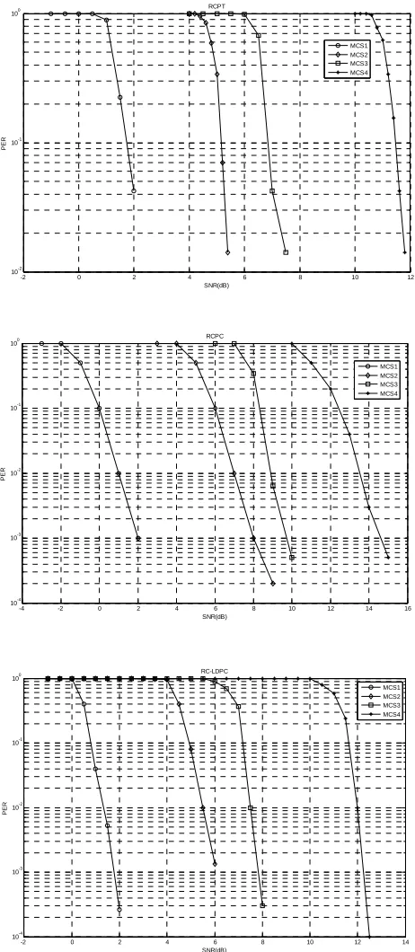
Figure 4 shows the PER values versus received SNR of each mode in coding step withRci, where i1, 2, 3
number of transmissions. We use the 1/2 QPSK, 3/4 QPSK, 1/2 16QAM and 3/4 16QAM modulations with RCPT code rates 1, 1/2 and 1/3 for each transmission respec-tively. The packet size is length and the puncturing follows the optimal rules according to [6] (Table 1). The constituent RSC encoders of PCCC turbo codec is the optimal encoder B proposed by [6] with rate 1/2, memory
1536
L
4
(i.e. 16 states) and generator matrix (1, gb/ga), where the generator polynomial ga and
b
g have octal representations and
respectively. The number of iterations is 8. The figures depict the simulated PER, the fitting curves and the val-ues derived from Equation (5).
(15)octal (13)octal
In order to have a more clear view on RCPT perform-ance combining with AMC, we should compare it with the other types of rate compatible codes. To this end, we implement also the aforementioned CLD first using RCPC (Rate Compatible Convolutional Code) and sec-ond using RC-LDPC (Rate Compatible Low-density Parity-check codes). We use the same rates for both two RC codes. Specifically, the RCPC is a convolutional encoder with rate 1/2, generator polynomial (171, 133)
Table 1. The block size and the puncturing matrix (in oc-toctal) of applied rcpt codes.
Family of Code Rates Block size
1 2/3 1/2
L = 1536
17 00 00
17 01 01
17 05 05
and constraint length 7 [9]. For LDPC, we employ the same codes as in [25] with rate 1/2 (1008,504) and a variable node degree equal to 3. The corresponding per-formance of these modulation and coding schemes (MCS) is depicted separately for each code in Figure 4.
-2 0 2 4 6 8 10 12
10-2 10-1 100
SNR(dB)
PER
RCPT
MCS1 MCS2 MCS3 MCS4
-4 -2 0 2 4 6 8 10 12 14 16
10-4
10-3 10-2 10-1
100
SNR(dB)
PE
R
RCPC
MCS1 MCS2 MCS3 MCS4
-2 0 2 4 6 8 10 12 14
10-4 10-3 10-2
10-1 100
SNR(dB)
PER
RC-LDPC
MCS1 MCS2 MCS3 MCS4
Figure 4. PER simulation performance of 4 AMC modes using RCPT, RCPC and RC-LDPC.
1For the rest of this document the packet error probability Pr will be
tra
af
i n
4. Performance Analysis and Numerical
Results
4.1. System Performance
In case of a general type-II HARQ that uses punctured codes, the probability of unsuccessful reception after Nt
nsmissions represents the event of decoding failure with code Rci ter i transmissions [10]. In case of
limited transmissions, the packet error probability of this using AMC mode n N under channel states
is given by [26] 1,..., ( ) n } (1)
{ , .., Nt
i n n
(2)
,.
n
1
( ) Nt ( i)
n i
PER
PER (6) By using (6) over for each retransmission and for each mode the packet error rates after transmissions are resulted. Thei
PER
..., 1,
n N i
i n
denotes the region boundaries for each MCS and obtained as follows
( ) 1 ( ) arg ( ) 1 0, 1
ln( ), 2,..., ,
i
i n
n t et
n i i a n g PER
N (7)
The is reached using the corresponding decoder when the imposed transmission at-tempts is reached either. Assuming
arg t et i PER i
Rc Nt
max
3
t
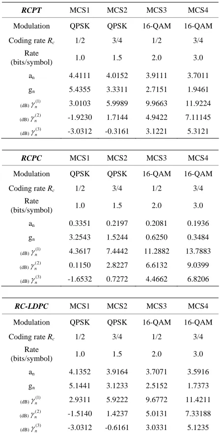
N and , the derived switching thresholds are listed in Table 2. Table 2 includes also the parameters of MCSs for convolutional and LDPC codes.
2
10
loss
PER
We next evaluate the system performance in terms of spectral efficiency when the AMC scheme is combined with type II HARQ (i.e. IR HARQ). In each transmi- ssion attempt, the number of transmitted bits is speci- fied according to RCPT code rates
i
i
L
...
1 2 M
Rc Rc Rc
i
Rn
as mentioned in Section 2. In addition to that, when mode
is used, each transmitted symbol carry
n
information bits where
2
log ( )
i Mn
Rc Mn derived
from Mary
1 /
modulation scheme. As in [9], we as-sume a Nyquist pulse shaping filter with bandwidth
s
B T , where Ts S
is the symbol rate. Afterwards, the spectral efficiency gives the bit rate in bits per symbol that can be transmitted per unit bandwidth and is given by e e L S L
(8)
In (7), where is the input information packet size and
L
[image:6.595.311.535.104.545.2]L is the average of transmitted symbols in order to
Table 2. the parameters of each rc-coded modulation at the physical layer.
RCPT MCS1 MCS2 MCS3 MCS4
Modulation QPSK QPSK 16-QAM 16-QAM
Coding rate Rc 1/2 3/4 1/2 3/4
Rate
(bits/symbol) 1.0 1.5 2.0 3.0
an 4.4111 4.0152 3.9111 3.7011
gn 5.4355 3.3311 2.7151 1.9461
(dB)n(1) 3.0103 5.9989 9.9663 11.9224 (dB)
(2)
n
-1.9230 1.7144 4.9422 7.11145
(dB)n(3) -3.0312 -0.3161 3.1221 5.3121
RCPC MCS1 MCS2 MCS3 MCS4
Modulation QPSK QPSK 16-QAM 16-QAM
Coding rate Rc 1/2 3/4 1/2 3/4
Rate
(bits/symbol) 1.0 1.5 2.0 3.0
an 0.3351 0.2197 0.2081 0.1936
gn 3.2543 1.5244 0.6250 0.3484
(dB)n(1) 4.3617 7.4442 11.2882 13.7883 (dB)
(2)
n
0.1150 2.8227 6.6132 9.0399
(dB)
(3)
n
-1.6532 0.7272 4.4662 6.8206
RC-LDPC MCS1 MCS2 MCS3 MCS4
Modulation QPSK QPSK 16-QAM 16-QAM
Coding rate Rc 1/2 3/4 1/2 3/4
Rate
(bits/symbol) 1.0 1.5 2.0 3.0
an 4.1352 3.9164 3.7071 3.5916
gn 5.1441 3.1233 2.5152 1.7373
(dB)n(1) 2.9311 5.9222 9.6772 11.4211 (dB)n(2) -1.5140 1.4237 5.0131 7.33188 (dB)
(3)
n
-3.0312 -0.6161 3.0331 5.1235
transmit an information packet. The average of transmit-ted symbols for each mode n is given by
1 ( 1) 1 2 ( ) ( ) t i N i i
n n n
i n n L L L R R
P (9)For cross-layer designed AMC schemes with n = 1,..,N
modes, the average spectral efficiency needs to be calcu-lated in order to evaluate system performance. By aver-aging the Ln values in the range of for
over all
( ) (1)
( ,..., Nt )
1,...,
1 1 ( ) ( ) 1 ( ) n n N i i n n n i L L p Rn
d
1 1 ( 1) ( ) ( )
2 1 ( ) ( ) t n n N N i i
n n n n
i n i
L
PER p d
Rn i
[image:7.595.70.275.212.691.2]
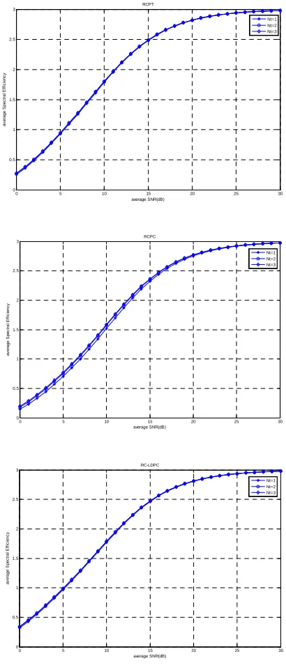
(10)Figure 5 depicts the average spectral efficiency of the combination of AMC and type-II HARQ relied on con-straints and . In this figure, it is shown the performance of AMC at physical layer when
3
t
N PERloss0.01
0 5 10 15 20 25 30
0 0.5 1 1.5 2 2.5 3 average SNR(dB) av e rage S pec tr al E ff ic ienc y RCPT Nt=1 Nt=2 Nt=3
0 5 10 15 20 25 30
0 0.5 1 1.5 2 2.5 3 average SNR(dB) av er ag e S p e c tr al E ff ic ie nc y RCPC Nt=1 Nt=2 Nt=3
0 5 10 15 20 25 30
0 0.5 1 1.5 2 2.5 3 average SNR(dB) av er a ge S pe c tr a l E ff ic ie nc y RC-LDPC Nt=1 Nt=2 Nt=3
Figure 5. The average spectral efficiency of each RC-coded modulation based on CLD design.
rate compatible punctured codes are employed under the constraints of the previous described cross-layer design. The parameters of each MCS are those listed in Table 2 considering a channel with Rayleigh fading phenomena as described above.
In Figure 6, we make contrast of the average spectral efficiency derived for each rate compatible punctured code. We illustrate the values of third transmission (i.e.
Nt = 3). Figure 6 shows the performance merit of RCPT against RCPC. This corroborates the benefit of turbo scheme against convolutional one in terms of communi-cation performance as it is well known. Indeed, this per-formance benefit is more evident in low regions of aver-age SNR than in high regions. Moreover, it is obvious that RC-LDPC achieves performance close to RCPT code. This is a useful outcome considering these two families of codes since LDPC codes are used in several standards and especially in space communications. The fact that turbo and LDPC codes show identical perform-ance has also concluded both in [27] and [28]. [27] has focused on performance in terms of PER values at the physical layer both in AWGN and multipath Rayleigh fading channel. [28] has proposed the PEG (Progressive Edge-Growth) construction method for LDPC codes and has concluded that turbo coding is identical of LDPC in terms of bit-level performance. To this direction, we evaluate the system performance under the aforemen-tioned cross-layer design and we have also concluded in the same result.
4.2. Comparison Complexity
However, the comparison between different codes should not be considered only in terms of performance related to communication efficiency. It should be also studied in terms of complexity even when the achieved system performance is identical between different codes (e.g. turbo and LDPC). Most of code complexity issues are
0 5 10 15 20 25 30
0 0.5 1 1.5 2 2.5 3 average SNR(dB) av erage S pec tr al E ff ic ienc y RCPT RCPC RC-LDPC
[image:7.595.318.533.539.685.2]related to computational complexity measuring the addi-tional operations required by each code. Another impor-tant aspect of code complexity relies on architectural issues introduced by code design. [29] studies the com-plexity of decoding algorithms that is measured in terms of computational operations such as multiplications, di-visions and additions. In Table 3 is listed the number of operations (i.e. additions, divisions, etc.) needed for each decoding procedure using the max-log MAP (Maximum A Posteriori) algorithm and the Viterbi algorithm in case of turbo and convolutional decoder respectively. These are actually the decoding algorithms that we have im-plemented in the RCPT and RCPC decoding procedure. In Table 3, M is the constraint length used by each en-coder at the transmitter side.
[image:8.595.64.282.446.683.2]Figure 7 shows the complexity of each decoding pro-cedure (i.e. turbo and convolutional) in terms of number of operations vs. the number of iterations and code con-straint length respectively. It is obvious from this figure that the decoding complexity in case of convolutional scheme is noticeably less than turbo case. In our case, the convolutional decoding procedure uses Viterbi decoder with constraint length equal to seven. On the other hand, turbo decoding uses max-log MAP with iterations equal to eight. The declension of turbo decoding complexity is close to two times the complexity of convolutional one since convolutional decoding scheme exhibits 1200 number of operations while turbo one exhibits approxi-mately 2400 number of operations.
Table 3. Complexity of turbo and convolusional decoders.
Number of Equivalent Operations
Turbo (Max-log
MAP algorithm) 28×2M–3
Convolutional
(Viterbi algorithm) 10×2M–3
1 2 3 4 5 6 7 8 9
0 1000 2000 3000 4000 5000 6000
Iterations (Turbo) / Constraint length (Convolutional)
C
o
m
p
le
x
it
y
(num
b
e
r of
o
p
erat
ions
)
Comparison complexity
Convolutional, M=7 Turbo, M=4, max-log-MAP
Figure 7. Complexity comparison between Turbo and Con- volutional decoders.
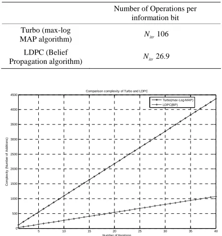
On the other hand, performance comparisons between turbo and LDPC codes in terms of decoding complexity have shown that when both codes achieve an identical performance then the decoding complexity remains ap-proximately the same. For instance, [28] have claimed that 80 iterations using the belief propagation algorithm produces the same decoding complexity as a turbo code does with 12 iterations using the BCJR decoding algo-rithm. [27] has studied the performance comparison be-tween turbo and LDPC codes in more details considering computational complexity. The authors have measured the computational complexity in terms of number of op-erations per iteration per information bit that they could be additions or comparisons. Table 4 shows the compu-tational complexity per information bit of the sub-opti-mum decoding algorithm for code rate R = 1/3. The com-plexity is expressed in relation to number of iterations
and it is illustrated in Figure 8.
itr
N
[image:8.595.310.536.450.690.2]Assuming the same configuration as in [27] the turbo decoding with 8 iterations when a max-log-MAP algo-rithm is used exhibits approximately the same complex-ity in terms of number of additions with the LDPC de-coding scheme that uses the BP algorithm. In our com-parative study, we use the decoding schemes from [28] that consist of a turbo decoder with max-log-MAP plus 8 iterations and LDPC decoder with PEG decoding graphs plus 80 iterations. Henceforth, it could be claimed that both turbo and LDPC decoders show the same computa-tional complexity.
Table 4. Complexity of turbo and LDPC decoding algorthms.
Number of Operations per information bit
Turbo (max-log
MAP algorithm) Nitr106
LDPC (Belief
Propagation algorithm) Nitr26.9
5 10 15 20 25 30 35 40
0 500 1000 1500 2000 2500 3000 3500 4000 4500
Number of Iterations
Com
p
le
x
it
y
(Nu
m
be
r o
f
A
d
di
ti
ons
)
Comparison complexity of Turbo and LDPC
Turbo(max-Log-MAP) LDPC(BP)
5. Conclusions and Future Work
In this paper, we have extended the cross-layer design combining AMC with HARQ using RCPT codes. To this end, a hybrid FEC/ARQ based on RCPT codes has been assumed. In previous works, the proposed CLD was in-troduced with uncoded modulations, convolutional and rate-compatible convolutional coded modulations dedi-cated to AMC schemes. In addition to that, we have im-plemented a CLD approach using puncturing techniques for rate compatibility purposes. The system performance has been evaluated for type-II hybrid ARQ mechanism. Moreover, we have illustrated comparative results of system performance of other rate compatible codes as convolutional and LDPC as well. In order to have a more comprehensive view of coding and decoding schemes we also discuss the computational complexity of each code separately, in terms of the required number of operations either in each iteration attempt or for each memory len- gth. However, since turbo coding and indeed punctured turbo codes are able to accomplish better performance with different RSC encoders and puncturing rules name- ly optimal encoding and puncturing [26], a future work should be the performance evaluation of AMC and HARQ combination implementing different encoders and puncturing rules using RCPT-ARQ.
6. References
[1] 3GPP TR 25.848 V4.0.0, “Physical layer aspects of. UTRA high speed downlink packet access,” March 2001.
[2] IEEE Std 802.16 – 2004, “IEEE standard for metropolitan area networks - Part 16: Air interface for fixed broadband wireless systems”.
[3] A. J. Goldsmith and S.-G. Chua, “Adaptive coded modu-lation for fading channels,” IEEE Transactions on Com-munications, Vol. 46, pp. 595–602, May 1998.
[4] S. Vishwanath and A. Goldsmith, “Adaptive turbo-coded modulation for flat-fading channels,” IEEE Transactions on Communications, Vol. 51, No. 6, pp. 964–972, June 2003.
[5] F. Babich, G. Montorsi, and F. Vatta, “On rate-compatible punctured turbo codes design,” EURASIP Journal on Applied Signal Processing, Vol. 2005, No. 6, pp. 784–794, May 2005.
[6] D. N. Rowitch and L. B. Milstein, “On the performance of hybrid FEC/ARQ systems using rate compatible punc-tured turbo (RCPT) codes,” IEEE Transactions on Com-munications, Vol. 48, No. 6, pp. 948–959, 2000.
[7] “Performance comparison of hybrid-ARQ schemes,” 3rd Generation Partnership Project (3GPP) Technical Speci-fication TSGR1#17(00)1396, October 2000.
[8] Q. Liu, S. Zhou, and G. Giannakis, “Cross-layer combining of adaptive modulation and coding with truncated ARQ
over wireless links,” IEEE Transactions on Wireless Com- munications, Vol. 3, pp. 1746–1755, September 2004.
[9] D. L. Wu and C. Song, “Cross-layer combination of hy-brid ARQ and adaptive modulation and coding for QoS provisioning in wireless data networks,” IEEE/ACM QShine, 2006.
[10] “Multiplexing and channel coding (FDD),” 3rd Genera-tion Partnership Project (3GPP) Technical SpecificaGenera-tion TS 25.212, Review 7.5.0, May 2007.
[11] C. Berrou, A. Glavieux, and P. Thitimajshima, “Near Shannon limit error-correcting coding and decoding: Turbo codes,” ICC, pp. 1064–1070, 1993.
[12] S. Benedetto and G. Montorsi, “Design of parallel con-catenated convolutional codes,” IEEE Transactions on Communications, Vol. 44, No. 5, pp. 591–600, May 1996.
[13] S. Benedetto and G. Montorsi, “Unveiling turbo codes: Some results on parallel concatenated coding schemes,” IEEE Transactions on Information Theory, pp. 409–428, March 1996.
[14] S. Benedetto, D. Divsalar, G. Montorsi, and F. Pollara, “Soft-output decoding algorithms in iterative decoding of turbo codes,” TDA Progress Report 42–124, Jet Propul-sion Lab, NASA, 15 February 1996.
[15] S. Benedetto, D. Divsalar, G. Montorsi, and F. Pollara, “A soft-input soft-output maximum a posteriori (MAP) mod-ule to decode parallel and serial concatenated codes,” TDA Progress Report 42–127, Jet Propulsion Lab, NASA, 15 November 1996.
[16] T. Maru, “A turbo decoder for high speed downlink pac- ket access,” Vehicular Technology Conference, VTC 2003-Fall, Vol. 1, pp. 332–336, 6–9 October 2003.
[17] F. Babich, G. Montorsi, and F. Vatta, “Design of rate- compatible punctured turbo (RCPT) codes,” ICC 2002, New York, Vol. 3, pp. 1701–1705, 2002.
[18] M. A. Kousa and A. H. Mugaibel, “Puncturing effects on turbo codes,” IEE Proceedings of Communications, Vol. 149, No. 3, pp. 132–138, June 2002.
[19] M. Dottling, T. Grundler, and A. Seeger, “Incremental redundancy and bit-mapping techniques for high speed downlink packet access,” in Proceedings of the Global Telecommunications Conference, pp. 908–912, December 2003.
[20] S. Bliudze, N. Billy, D. Krob, “On optimal hybrid ARQ control schemes for HSDPA with 16QAM,” WiMob’ 2005, August 2005.
[21] M. Mohammad and R. M. Buehrer, “On the impact of SNR estimation error on adaptive modulation,” IEEE Communications Letters, Vol. 9, No. 6, pp. 490–492, June 2005.
[22] D. Athanasios and K. Grigorios, “Error vector magnitude SNR estimation algorithm for HiperLAN/2 transceiver in AWGN channel,” TELSIKS ’05, Vol. 2, pp. 415–418, 2005.
and architecture (Release 5),” September 2003.
[24] T. Duman and M. Salehi, “Performance bounds for turbo- coded modulation systems,” IEEE Transactions on Com-munications, Vol. 47, No. 4, pp. 511–521, April 1999.
[25] Y. L. Zhang and D. F. Yuan, “Rate-compatible LDPC codes for cross-layer design combining of AMC with HARQ,”2006 6th International Conference on ITS Tele- communications Proceedings, pp. 537–540, June 2006.
[26] D. L. Wu and C. Song, “Cross-layer design for combining adaptive modulation and coding with hybrid ARQ,” IWCMC ’06, Vancouver, British Columbia, pp. 147–152, 2006.
[27] N. Ohkubo, N. Miki, Y. Kishiyama, K. Higuchi, M. Sa-wahashi, “Performance comparison between turbo code and rate-compatible LDPC code for evolved UTRA downlink OFDM radio access,” MILCOM ’06, Wash- ington DC, 2006.
[28] X. Y. Hu, E. Eleftheriou, and D. M. Arnold, “Regular and irregular progressive edge growth tanner graphs,” IEEE Transactions on Information Theory, Vol. 51, pp. 386 –398, January 2005.