Maximum Likelihood Detection for Detect-and-Forward
Relay Channels
Azlan Abd Aziz, Yasunori Iwanami
Department of Computer Science and Engineering, Nagoya Institute of Technology, Nagoya, Japan E-mail: [email protected]
Received November 30, 2010; revised December 17, 2010; accepted December 30, 2010
Abstract
This paper introduces a simple combining technique for cooperative relay scheme which is based on a De-tect-and-Forward (DEF) relay protocol. Cooperative relay schemes have been introduced in earlier works but most of them ignore the quality of the source-relay (S-R) channel in the detection at the destination, although this channel can contribute heavily to the performance of cooperation schemes. For optimal detection, the destination has to account all possible error events at the relay as well. Here we present a Maximum Likeli-hood criterion (ML) at the destination which considers closed-form expressions for each symbol error rate (SER) to facilitate the detection. Computer simulations show that significant diversity gain and Packet Error Rate (PER) performance can be achieved by the proposed scheme with good tolerance to propagation errors from noisy relays. In fact, diversity gain is increased with additional relay nodes. We compare this scheme against the baseline Cooperative-Maximum Ratio Combining (C-MRC).
Keywords:Cooperative Relay, Detect-and-Forward, Maximum-Likelihood Criterion Detection
1. Introduction
Cooperative communication has been developed as a promising technique to realize spatial diversity through user cooperation [1]. Various relaying schemes have been proposed to explore the benefits of cooperative communication, mainly divided into three categories, including Decode-and-Forward (DF), Amplify-and-For- ward (AF) [1-3] and Detect-and-Forward (DEF). In DF, the relay always decodes, re-encodes and re-transmits the decoded signal to the destination. That is, any errors at the relay can be corrected and thus, error propagation can eventually be avoided. On the other hand, AF simply amplifies the received signals and forwards them to the destination after power scaling. The disadvantage of AF strategy is that it will also forward noises which received at the relay. Another relaying protocol which is simple in complexity is DEF where the relay simply detects the signals (hard-decision detection), modulates before for-warding to the destination. With DEF, in [4] the author has shown that the diversity gain can also be achieved provided the destination knows the relay probability of error.
Recently, many works were devoted to improve the relay complexity and yet strive for better error rate
per-formance. For example, our earlier works in coded co-operative schemes [5] adopted DEF at the relay node with further enhancements at the destination. The desti-nation employs Maximum Likelihood criterion detection (ML) to combine the direct and relayed transmissions. However, this detection at the destination does not ac-count sufficiently the error probability of making errors at the relays resulting in serious performance degradation. In coded relay schemes, the channel decoder is initialized with channel log-likelihood ratio (LLR); hence, requires high accuracy of LLR computation. The authors in [4] have developed a piece-wise linear receiver approximat-ing the ML criterion detection that requires knowledge of the average signal-to-noise-ratio (SNR) of the first hop. However, this scheme cannot achieve full diversity for more than one relay. In [6], another combining technique namely Cooperative-Maximum Ratio Combining (C-MRC) is introduced that approximates the ML detector. Unfor-tunately, C-MRC results in serious propagation error
under asymmetrical networks when SNR of R-D link is
coopera-tive relaying scheme using DEF protocol with limited Channel State Information (CSI). In [4-12], the authors have derived sub-optimal receivers but exploiting effec-tively perfect knowledge of all links is still an open problem, specifically the error probability at the relay. However, many of the previous works assumed that the destination only knows the average probability of symbol error at the relays. Since the detection rule in ML crite-rion detection at the destination has to consider every symbol error probability, this error model may substan-tially affect the attainable end-to-end performance. Thus, to guarantee an optimal ML criterion detection, the des-tination needs to know the error characteristics of the S-R link (perfect CSI) in the form of relay error prob-abilities.
In this paper, we aim at providing the destination with a more accurate CSI in its decision criterion. While the idea itself of having perfect CSI is not new [9,11,13], the CSI in the previous works is calculated based on the assumption of average error probability. For binary phase-shift keying (BPSK) case, the solution is
straight-forward, but for quarternary phase-shift keying (QPSK)
and higher modulation constellation, the Euclidean dis-tance between symbols become no longer the same; hence the symbol error probability can also differ. To circumvent this problem, here we develop a simple ML detection algorithm for the destination node for QPSK modulation. For simplicity, we analyze this ML per-formance with a simple DEF in uncoded cooperative relay networks and compare against the baseline C-MRC. Unlike in C-MRC, the instantaneous CSI in the proposed scheme involves Q-function expression for each symbol in the modulation which provides accurate knowledge of S-R link. Our scheme also outperforms C-MRC espe-cially when SNR of R-D link is sufficiently high or low (asymmetrical network). We show through computer
simulations that the performance of the proposed coop-erative relay schemes can be improved significantly par-ticularly in multiple relay nodes. We observe that there is remarkable potential to achieve increasing orders of di-versity with better packet error rate (PER) performance than that of C-MRC.
The organization of this paper is as follows: Section 2 is System Description and the proposed scheme, Simula-tion Results and Discussions are given in SecSimula-tion 3, and finally in 4, the paper is summarized. The derivation of the individual SER for QPSK in Gray mapping is pre-sented in the Appendix.
2. System Description
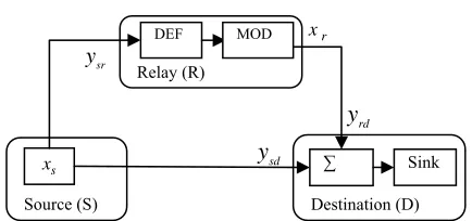
With reference to Figure 1, we first consider a classical
[image:2.595.315.532.72.174.2]relay model in which only one relay (R) assists the source
Figure 1. Block diagram of the cooperative relay system with a DEF protocol. MOD denotes the modulation of the received signal at the relay.
(S) to communicate with the destination (D). We assume each node has only one antenna and is not equipped with cyclic redundancy-check (CRC) codes. In this paper, we consider a time division multiple access (TDMA) mode where data transmission is split into two phases, that of the source node and that of the relay node. It is assumed that all the receiving nodes have perfect CSI. Further-more, the destination also requires CSI of all three links for detection.
2.1. System Model
At timeslot 1, the source broadcasts its information, xs
to the destination and the relay with the average power
s
E . Due to the broadcast nature of wireless channel,
both the destination and the relay receive a noisy obser-vation of xs denoted by ysd and ysrrespectively in
the following relation
sd sd s sd
sr sr s sr
y h x n
y h x n
(1) where the subscripts indicate the node relation such that
sdand
h sr are independent complex-valued channel
gains for the S-D and S-R links respectively. For sim-plicity, all channels are Quasi-static Rayleigh fading
h
channels i.e., hsd ~
0,s2d
and
2
0,
sr sr
h ~ ,
where
, 2
denotes a complex Gaussian randomvariable with mean and variance 2;
sdand
n sr
are modeled as independent additive white Gaussian
noise with zero mean and equal variance 0 at the
destination and relay respectively. We assume that the average SNR for all links are the same denoted as
n N
0 s
E N
, while the instantaneous SNR is represented
as 2
sd sd
and 2
sr sr
respectively. The relay
performs a hard-decision detection (DEF) and re-modu-
lates (MOD) the detected signals as xrwith the same
average power Esfor re-transmissions in timeslot 2. The
symbol received at the destination is given as
rd rd r rd
y h x n (2)
r
x
DEF
Destination (D) rd y Relay (R)
MOD
sr
y
y
Source (S)
sd
s
where and . The
instantaneous SNR is
0, 2rd rd
h ~ nrd ~
0,N02
rd rd
.
At the destination, the signals from the source and the relay node are combined to recover the original source data.
2.2. Processing at the Destination 2.2.1.Baseline Scheme
Many cooperative relay schemes use MRC to exploit spatial diversity gain. It is one of the simplest and prac-tical approaches when S-R link is reliable. However, this conventional MRC at the destination cannot guarantee full diversity in cooperative schemes. The destination node requires perfect (instantaneous) CSI of S-R link with effective combining.
In [6], the authors have proposed an improved version of MRC termed as C-MRC. The combined signal at the destination node is given by
* min *
cmrc sd sd rd rd rd
y h y h y
(3)
where min min
sr, rd
, srand rd areinstanta-neous SNR of the S-R and R-D channels respectively. The usual intuitive meaning associated with (3) is that when sr is high, the detector places full confidence to
the arriving signals from the relay. In case of low sr,
the confidence is weighted according to the ratio of both hops, that is S-R-D link.
2.2.2. Proposed ML-based Combining Strategy
In this section, we first derive the proposed ML combin-ing technique in case of one relay. In the subsequent sec-tion, we generalize it to multiple relays. The main pur-pose of this algorithm is to optimally combine the noisy
signals received at the destination node, sd and rd.
It should be noted here that the maximum likelihood detector at the destination should also consider the effect of detection errors at the output of the relay. Such errors are mainly due to fading events in the S-R link. When this link is affected by a deep fade, the detection errors committed at the relay are propagated to the destination. To mitigate these errors which are originated from both source-relay and relay-destination links, an end-to-end ML-based detector should be employed. Thus, the basic assumption for this strategy is that the destination node makes a coherent detection for the signals from the source and the relay nodes requiring all three channels to be known at the destination node, i.e.,
y y
, ,
sd s
h hr rd and
the noise variances are available at the destination (only the received symbol
h
sr is not known). This is a
stan-dard assumption based on the fact that these parameters have been estimated as a priori. For a fair comparison,
we maintain the same assumptions applicable for the baseline scheme C-MRC. The proposed ML decision rule at the destination is determined by taking all the possible symbol detection scenarios both at the destina-tion and the relay. By applying Bayes’ rule, the decision criterion can be shown as
y
ˆ arg max , ,
, arg max , , , arg max , arg max s s r s s s
s s r sd sd rd rd
x
s sd sd s rd rd r
x sd sd rd rd
s sd sd s
rd rd r s rd rd r
x x
x sd sd rd rd
sd sd s rd r x
x P x x y y y y
P x P y y x P y y x
P y y y y
P x P y y x
P y y x x P y y x
P y y y y
P y y x P y y
, , , r sd r s
rd rd r x x
x x
P y y x
(4) From (4), by considering the potential errors at the re-lay node, the decision criterion can be expanded as
ˆ arg max
s
r
s sd sd s
x
r s rd rd rd r s
r s rd rd r
x
x P y y x
P x x P y y x x
P x x P y y x
(5)where we assume P x
s 1M e.g.,M= 4 for QPSK; denotes the finite set of the constellation and yis the
observation space for the respective received symbol. First, we assume that the transmit signals are modulated by QPSK and later, we consider a special case of BPSK. Throughout the sequel, we use capital P as the
probabil-ity function. From (5), after some simplifications, the detector at the destination will find xˆs, an estimate of
s
x by using the following criterion
ˆ arg max
s
r
s sd sd s
x
r s rd rd r s
r s rd rd r x
x p y x
P x x p y x x
P x x p y x
(6)
where psd
ysd xs
is the probability density functiontransmitted data xs and prd
yrd xr xs
is the PDFof the relayed signal rd conditioned on the equality of both transmitted symbols
y
xr xs
.. However thebracketed terms in (6) has to consider the error probabil-ity of the received signals ysr
at the relay accounting the SER of each signal point.
For QPSK case, the solution is not straightforward due to different Euclidean distance among symbols. In QPSK, a symbol with two bits, xs b b1, 2
3, 4
takes from the constellation set
s s s s1, ,2 . Assuming the Graymapping, we represent the complex symbols of as
4 . The
detec-tion at the destinadetec-tion is performed jointly by the ML criterion and we can expand (5) as
1 2
s 0,0 ,s
1,0
,s3
1,1 ,s 0,1
1 2 1 2 3 rd s rd rd 2 2 1 2ˆ arg max
s
rd rd r s
j
rd r s
j
s s rd r s
x
j
rd r s
p y x x
p y x x
x p x p y x x
p y x x
d ysd
(7)
where1, 2 and 3 denote the symbol error
prob-abilities from s1s3, s1s2 and s1s4
respec-tively; 1 and 23 are analytically expressed as
the Gaussian Q( ) function where
: 1
2
2 2
xQ x
exp t dt. In the 2nd term of(6), we include the multiplicative error term in
exponen-tial function, j with the following equality j
r s
x x
where 0, , ,
2 2
denoting the phase changes
that depends on the symbols transmitted from the relay. This means that (7) takes into account that the relay does not operate error-free. In this paper, we derive closed– form expressions for the probability of error for each constellation symbol for QPSK as
1 2 2 0 0 ( ) 1 4 2 j r s s
P x x
E E erfc Q N N s (8) 2 2 3 2 0 0
( r s j ) r s
s s
P x x P x x
E E Q Q N N 2 j (9)
where erfc is the complementary error function. When
sd
y and are received at the destination, by
insert-ing 1 2 3 4
rd
y
, , or
s s s s to xs and examining how large the
argument value from the augment (7), we can determine
the transmit signal point xs from the finite set in
QPSK constellation. The PDF for each term correspond-ing to the followcorrespond-ing expressions:
20 0
| exp
2 2
j
rd rd s
j s
y h x
x N N 1
rd rd r
p y x
(10)
where 0, , ,
2 2
.Detail derivations of (8) and
(9) are presented in the Appendix. It is clear from (8) and (9) that each QPSK symbol takes on a different symbol error probability. The analytical results presented thus far in previous works have been derived from studies which examined the SER problem assuming that the symbol error probability of each QPSK symbol is equally likely. Thus, these results cannot be treated as offering a com-plete ML solution. Note that another advantage in the proposed ML over C-MRC is its flexibility of combining different modulated signals from different nodes since each link can be treated independently (symbol-wise detection). In C-MRC, if the potential errors cannot be accurately modeled, maximizing the SNR would not result in the improvement of the scheme.
For completeness, we also examine the scheme in the absence of the CSI of S-R link at the destination node. The destination ignores the error possibility at the relays
i.e., 1230 in (7). Hence, we obtain
ˆ arg m
s
ax
s sd sd s rd rd r s
x
x p y x p y x x
(11)
One can gain insight about (11) that it is identical with the conventional MRC. This means the combiner at the destination does not explicitly take into account the un-certainty of the relay decisions when S-R link is errone-ous.
Next, we present a special case when BPSK is used, instead. For BPSK, the relay decision process can be
simply modeled as a binary symmetric channel (BSC)
with the probability of a binary decision error at the relay
r xs
P x . This is because the S-R link is modeled as a
Quasi-static Rayleigh fading channel and each channel is equivalent to a specific AWGN channel having a
com-plex gain of sr. When the relay node R receives the
signal from the source node, it does ahard decision
h
r
x
for sr
The relay decision process can be characterized by a random variable
y and forwards it to the destination node.
defined as
: 1 : 0 r r s s x x x x
x
withE
1 b P x
r s where bis the prob-ability of bit error at the relay. Therefore, p y
rd xr
can be shown as
1 0
r s rd rd r s rd r
r s rd rd r s
rd rd r s
rd rd r s
P x x p y x x
p y x
P x x p y x x
P p y x x
P p y x x
(13)
where the transition PDF of prd
yrd xr xs
is repre-sented by
20 0
1 exp
2 2
rd rd s rd rd r s
y h x
p y x x
N N
(14)
In (14), xs is the complement ofxs
1, 1
. Inserting the conditional PDF into (13), the transition PDF of this relayed path for BPSK case can be shown as
1
20 0
2 1
0 0
1
1 exp
2 2
1 exp
2 2
rd rd s rd r
rd rd s
y h x p y x
N N
y h x N N
(15)
In brief, the proposed scheme features:
1) A simple detector which is capable of mitigating the potential errors at the noisy relays.
2) A new error model which serves as the side infor-mation for the detection at the destination by considering individual SER of the signal points in QPSK. Since (7) considers individual SER in its decision, our framework also suits well for other type of modulations Nonetheless, since having complete CSI for S-R link can be re-source-exhaustive, we propose another scheme as in (26) for QPSK considering only average SER for each modu-lation.
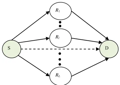
2.3. Multiple-relay Scheme (MRS)
In this section, we generalize (7) to multi relay schemes (MRS) withLrelay nodes denoted as R ll,
1, , L
.The system model for MRS is shown in Figure 2 where
in the 1st timeslot, the source broadcasts its information
to the destination (dashed line) and the relay nodes. In
the following timeslot, relay l re-transmits the
received signal to the destination in TDMA orthogonal channels where the corresponding received symbol at the
destination is rd l r l rd l, . Note that the total
timeslots are . The orthogonality is observed due to
the constraints in the practical radio transceivers which cannot transmit and receive at the same time. Finally, at
1
l
rd l
1
R
, , ,
y h x n
L
S D
R1
Rl
[image:5.595.323.523.76.217.2]RL
Figure 2. Multiple relay scheme in parallel channel setup.
the destination, all signals transmitted from the relays are combined by the proposed ML combining technique. All relays are considered to employ uniform relay function e.g. DEF.
From (5), we let the bracketed term denote the deci-sion criterion for the received symbol from a relay Rlas
,
, , , ,
, , ,
ˆ |
r l
rd l r l s rd rd l r l s
r l s rd rd l r l s x
p P x x p y x x
P x x p y x x
(16)Therefore, for MRS, we can rewrite (5) compactly as
,1
ˆ arg max ˆ
s
L
s sd sd s rd l
x l
x p y x p
(17)The destination will detect the symbols from all relays (plus the direct link) by using the proposed ML assuming that the perfect knowledge of every S-R link is available at the destination.
3. Simulation Results and Discussions
We analyze Packet Error Rate (PER) against average SNR in decibel (dB). We first assume the source and
relay nodes transmit with the same average power Es
resulting in the average SNR, Es N0 (symmetrical
network). For C-MRC, we also consider the destination has a perfect knowledge of S-R links (i.e., instantaneous
SNR) and perfect channel estimation is assumed. In this simulation, we only consider blind cooperative relaying schemes where relay nodes always re-transmit to the destination whether the signal is correctly detected or contains errors. No automatic repeat request (ARQ) pro-tocol is used to avoid the error propagation from the re-lay nodes to the destination.
First, we check the PER performance of the proposed scheme as shown in (7) against the baseline for multiple relay nodes i.e. L1, 2 and 3. In Figure 3, as expected,
the proposed schemes outperform C-MRC (3) in all cases
Figure 3. PER comparison between the proposed ML scheme and C-MRC (dashed lines) using DEF protocols for
relays. = 1, 2 and 3
L
for 1, 2 and 3 relay cases respectively. In particular, we can also observe that all the cooperative schemes achieve full order diversity as observed from the slopes of the curves i.e., 10 L 1 10 dB
(diversity order of L1) but a significant decrease in diversity gain for No CSI cases (11). This result demonstrates that the proposed algorithm has better accuracy of symbol detection dueto the sufficient statistics of the received signals sd
and . For this reason, the conditional probability
y
rd
y
rd rd r
p y x
can be computed using the observations
rd rd r s
p y x x
. As for the No CSI case, the diversityorder of 1 is achieved for all cases. PER performance
further degrades from relay case. We
note that when no CSI of S-R link is available at the des-tination, the decision by the destination are done using significantly erroneous assumptions that there are no detection errors at the relay nodes. As a result, they con-vey false reliability measures to the decoder and the per-formance is noticeably affected (more than 15 dB loss at
compared to the proposed ML schemes for all cases). In practice therefore, a cooperative scheme with DEF which does not account for the S-R CSI may not be very effective.
3, 2 and 1
L
3
PER 10
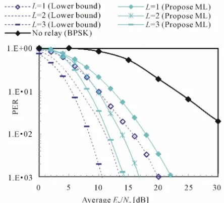
Second, we simulate the lower bounds corresponding to each case where a perfect relay is employed i.e., the
same signal from the source is transmitted to the
destina-tion (complete MRC). As shown in Figure 4, for PER =
the gap between the lower bound and the proposed scheme is 2 dB for 1 relay case and 3 dB for 2 and 3 re-lay cases each. In perfect rere-lay cases, the rere-lays just rep-licate the same data as the source node; hence the per-formance can be regarded as the lower bound of the co-operative schemes. We can also notice that the gap to the
lower bounds become almost constant if larger network is applied (multiple relays). This performance improve-ment is achieved by employing only a hard-decision protocol (DEF) at the relay nodes. Such a system design is practical for wireless networks which usually cannot compromise on the high energy consumption and longer time delay at the relays. We also plot no relay case using BPSK modulation for fair comparison. It is clear that the gain from the proposed ML scheme is significantly large due to cooperative gain.
3
10
[image:6.595.313.535.246.448.2]Third, we investigate the proposed ML schemes when the detector considers the average SER of QPSK in the decision criterion (26) as shown in Figure 5. Interestingly,
Figure 4. PER comparison between the lower bounds (dashed lines) and the proposed ML schemes (solid lines) in multiple relay schemes. The lower bounds are simulated with perfect relays.
[image:6.595.324.537.508.681.2]their performance is almost the same in all SNR regions as C-MRC. By using average SER in the algorithm, the observation in prd
yrd xr xs
is equally weightedfor all QPSK symbols. As a result, this has caused some degradation in PER performance compared to the
pro-posed pure ML case (7) as shown in Figure 3. In fact,
the convergence of the two schemes is also expected due to the approximation at high SNR of the baseline scheme [6]. Note that keeping perfect CSI of S-R link at the des-tination can be energy consuming and involve higher computations i.e., 1 and 2 required for perfect CSI,
but only 0 is required for the average case. Thus, this proposed ML strategy poses a practical solution which constitutes a good tradeoff between the perfect CSI re-quirement and error rate performance
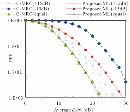
Finally, in Figure 6, we simulate the proposed scheme
and C-MRC when only one relay node is used but we vary the average SNR for R-D link rd and we keep the
average SNR for S-D link and S-R link the same,
sd sr
. We simulate the schemes at three
differ-ent scenarios of R-D link quality: + 15 dB (+15 dB),
– 15 dB (–15 dB) and rd (equal). In view of
this result, we infer that the proposed scheme can out-perform C-MRC when R-D link has sufficiently high
SNR quality (+15 dB) with 1dB gap at PER = 10-3
and
2.5 dB gap at PER = 10-2 for low SNR quality (–15 dB).
[image:7.595.60.282.488.679.2]When R-D link has higher SNR compared to S-D or S-R links, the combined signal at the destination is dominated by the erroneous signal from the relayed link. Thus, the PER performance is degraded further compared to the case of equal SNR. This significant performance demon-strated by the proposed ML scheme renders it more suit-able when the relayed link has poor SNR quality. In
Figure 6. PER comparison between the proposed ML scheme (solid lines) and C-MRC (dashed lines) when the average SNR of R-D link,
rd
γ varies at L= 1 relay case.
C-MRC, one can also check from (3) that the subopti-mality of C-MRC becomes inherently evident when the weighted signal from the relayed link becomes larger than that of the direct link. C-MRC effectiveness is largely conditioned on the link quality of R-D link over S-D link (direct path). Surprisingly, it can be easily seen that the proposed ML scheme achieves the advantages of the cooperative gain by using only simple DEF protocol with increasing improvement in multiple relay schemes. In particular, although the received signals at the relays are noisy and only DEF is used at the relays, the pro-posed scheme improves achievable PER performance. Furthermore, the proposed scheme also even provides better error rate performance at low and high SNR of R-D link which becomes an added advantage compared to C-MRC.
4. Conclusions
In this paper, we developed a new signal combining strategy based on ML criterion for cooperative relay scheme which accounts the potential errors at relays. The errors are expressed as the Gaussian Q-function for each SER in QPSK symbols. By applying these expressions in the detection at the destination, we can accurately model the transition probabilities for the erroneous transmission from noisy relays. The proposed ML scheme is superior to the conventional C-MRC in PER performance in all cases under the same CSI requirement. The proposed ML scheme has more flexibility in implementation compared to C-MRC depending on CSI at the destination. In fact, unlike C-MRC, the proposed scheme remains resilient to propagation errors even if R-D link has different SNR quality. In addition, with DEF protocol, this proposed ML scheme has shifted the processing complexity to the destination node whilst the relay nodes can conserve the energy and simple data processing. Thus, this makes this proposed strategy amenable to implementation especially for resource-constraint environment such as wireless sensor networks.
5. Acknowledgements
This study has been supported by the Scientific Research Grant-in-aid of Japan No. 21560396, the Telecommuni-cation Advancement Foundation (TAF) and the A-STEP by JST (Japan Science and Technology Agency).
6. References
1109/TIT.2004.838089
[2] A. Sendonaris, E. Erkip and B. Aazhang, “User Cooper- ation Diversity Part I and Part II,” IEEE Transactions on Communications, Vol. 51, No. 11, November 2003, pp. 1927-1948. doi:10.1109/TCOMM.2003.818096
[3] A. Nosratinia and T. E. Hunter, “Diversity through Coded Cooperation,” IEEE Transactions on Wireless Communi- cations, Vol. 5, No. 2, February 2006, pp. 283-289. doi:10. 1109/TWC.2006.1611050
[4] D. Chen and J. N. Laneman, “Modulation and Demo- dulation for Cooperative Diversity in Wireless Systems,” IEEE Transactions on Wireless Communications, Vol. 5, No. 7, July 2006, pp. 1785-1794. doi:10.1109/TWC.2006. 1673090
[5] A. A. Aziz, Y. Iwanami and E. Okamoto, “On the Im- provement of Maximum Likelihood in Multiple Relay Systems,” Proceedings of IEEE Wireless Communications & Networking Conference, Sydney, 18-21 April 2010, pp. 1-6. doi:10.1109/WCNC.2010.5506662
[6] T. Wang, A. Cano, G. Giannakis and N. Laneman, “High Performance Cooperative Demodulation with Decode-and- Forward Relays,” IEEE Transactions on Wireless Commu- nications, Vol. 55, No. 7, July 2007, pp. 1427-1438.
[7] B. Djeumou, S. Lasaulce and A. G. Klein “Combining Decoded and Forwarded Signals in Gaussian Cooperative Channels,” Proceedings of IEEE International Symposium on Signal Processing and Information Technology, Van- couver, 27-30 August 2006, pp. 622-627.
[8] M. R. Souryal and H. You, “Diversity Performance of a Practical Non-Coherent Detect-and-Forward Receiver,” Pro-
ceedings of IEEE Global Telecommunications Conference, New Orleans, 30 November-4 December 2008, pp. 1-6.
[9] M. Benjillali and L. Szczecinski, “A Simple Detect-and- Forward Scheme in Fading Channels,” IEEE Communica- tions Letters, Vol. 13, No. 5, May 2009, pp. 309-311. doi: 10.1109/LCOMM.2009.090139
[10] M. N. Khormuji and E. G. Larsson, “Receiver Design for Wireless Relay Channels with Regenerative Relays,” Pro- ceedings of IEEE International Conference on Communi- cations, Glasgow, 24-28 June 2007, pp. 4034-4039.
[11] J. P. K. Chu, R. S. Adve and A. W. Eckford, “Using the Bhattacharyya Parameter for Design and Analysis of Cooperative Wireless Systems,” IEEE Transactions on Wireless Communications, Vol. 8, No. 3, March 2009, pp. 1384-1395. doi:10.1109/TWC.2008.080071
[12] K. Lee and L. Hanzo, “MIMO-Assisted Hard versus Soft Decoding-and-Forwarding for Network Coding Aided Re- laying Systems,” IEEE Transactions on Wireless Commu- nications, Vol. 8, No. 1, January 2009, pp. 376-385. doi: 10.1109/T-WC.2009.080048
[13] X. Hu, M. Benjillali and L. Szczecinski. “Bit Error Rate for Rectangular QAM with Arbitrary Constellation Mapping in Nakagami-m Channels,” Wiley Journal on Wireless Communications and Mobile Computing, Vol. 8, No. 1, 2008, pp. 93-99. doi:10.1002/wcm.437
[14] M. S. Alouini and A. J. Goldsmith, “A Unified Approach for Calculating Error Rates of Linearly Modulated Signals over Generalized Fading Channels,” IEEE Transactions on Communications, Vol. 47, No. 9, September 1999, pp. 1324-1334. doi:10.1109/26.789668
Appendix
Derivation of Symbol Error Rate (SER) of QPSK Signals in Gray Mapping
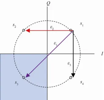
Employing the two-dimensional (2-D) Gaussian Q- func-tion representafunc-tion, we present closed-form expressions
for the individual SER of each QPSK signal. Figure 7
illustrates the signal points for QPSK when Gray map-ping is used. Let us denote I and Q
3(1,1),s
as the in-phase and quadrature components respectively. Since each complex symbol of QPSK corresponds to two binary bits, as
pre-sented in Figure 7 we assign the respective symbols
accordingly.
1 2 4
s (0,0),s (1,0),s (0,1)
1. Derivation of ε1
In this sub-section, we derive the symbol error probability of s1s3. Figure 7 depicts the difference
of Euclidean distance between 1and other symbols.
Here we assume 2 3
s
. First, it is convenient to define several assumptions used in the analysis.
Consider the i-th received signal vector si(X Yi, ),i
of QPSK transmitted over an AWGN
channel with the channel gain . Hence, ( ,
{1, 2,3, 4}
i
h X Yi i) in
i
s is given by the following in-phase and quadrature
components
Xi, Yi
cos
t nX, ins
t nY (18)where and are jointly Gaussian with zero mean
and equal variance such that the expected value is
X
n nY
0
N
2 2
0
1 2
X Y s
E n E n E N (19)
The symbol error probability when s1 is sent and s3 is detected can be shown by the 2-D Gaussian probability
Figure 7. Signal QPSK symbols and symbol error prob-abilities.
integral as follows
2 2
0 0 1
0 0
1 1
1 exp 2 2
2 2
X Y
dXdY
N N
(20) (20) can be analytically calculated and we can re-write it as
2 1
0 2 0
1
4 2
s
s
E erfc
N E Q
N
(21)
where erfc( ) is the complementary error function.
2. Derivation of ε2
In this sub-section, we derive the transition probability of a signal point that falls into an adjacent quadrant e.g.,
1 2
s s
Similarly, from (20)
2 2
0
2 0
0 0
1 1
1 exp 2 2
2 2
X Y
dXdY
N N
(22) Then, (22) can be analytically calculated and we ob-tain
2 2
0 0
2
0 0
1 1
2 2 4 2
s s
s s
E E
erfc erfc
N N
E E
Q Q
N N
(23)
Proof: Derivation of 0 using 1, 2and 3 which
is equivalent to the standard closed-form expression of the average probability of error for QPSK in AWGN channel [14].
In this sub-section, we provide an alternative
deriva-tion for the average SER of QPSK, 0. We prove that
the sum of all individual SER of QPSK symbols amounts to the average SER of QPSK. Since23,
2
2 3
0 0
1 1
2 2 4 2
s s
E
erfc erfc
N N
E
[image:9.595.308.540.92.173.2] [image:9.595.309.538.386.471.2] [image:9.595.88.259.527.690.2]Therefore, the average SER for QPSK is simply
0 1 2 3
2
0 0
2
0 0
1
2 4 2
2
s s
s s
E
erfc erfc
N N
E E
Q Q
N N
E
0
(25)
For comparison, we also investigate the effect of hav-ing only average SER in the proposed ML algorithm. From (7), by setting123 , we have the
fol-lowing criterion
0
0
2 0
2 0
1 3 |
|
ˆ arg max | |
|
s
rd rd r s j rd rd r s
j
s sd sd s rd rd r s
x
j rd rd r s
p y x x
p y x x
x p y x p y x x
p y x x