© 2019, IRJET | Impact Factor value: 7.211 | ISO 9001:2008 Certified Journal | Page 166
Maximizing the Solar Panel Output with the Help of Microcontroller
Based Tracker
Ms. Darshana K. Titare
1, Ms. Prajakta K. Gangasagar
2, Prof. M. J. Nemade
31,2
UG Scholar, Electrical Engineering (E&P), DESCOET, Dhamangaon (Rly.), Maharashtra, India,
3
Assistant Professor, Electrical Engineering (E&P), DESCOET, Dhamangaon (Rly.), Maharashtra, India,
---***---Abstract –
Sustainable power source arrangements arewinding up progressively prominent. Photovoltaic (sun oriented) frameworks are nevertheless one precedent. Augmenting power yield from a close planetary system is attractive to expand effectiveness. So as to augment control yield from sun based boards, one needs to keep the boards lined up with the sun. Accordingly, a methods for following the sun is required. This is unquestionably a more savvy arrangement than acquiring extra sun powered boards. It has been evaluated that the yield from sun oriented boards can be expanded by 30 to 60 percent by using a following framework rather than a stationary exhibit. In this paper, a model for a microcontroller-based multi-work sun oriented following framework is portrayed, which will keep the sun based boards lined up with the sun so as to augment productivity. The most extreme power point following (MPPT) information can be transmitted continuously to other universes needing this information.
Key Words: Solar energy, Photovoltaic, Solar tracking,
Microcontroller, Power
1. INTRODUCTION
All know about the weariness of petroleum derivatives and nursery impact, a standout amongst the most essential issue. There ought to be perfect wellspring of vitality. Efficient power vitality offering the guarantee of clean and inexhaustible vitality assembled from self-recharging sources. For the nation like India Solar Photovoltaic Energy is the best choice. The vitality got from the Sun is a huge number of time of our present day prerequisite. The greatest vitality must be gotten from the radiation achieving the earth surface. Following framework is utilized to extricate the most extreme conceivable power from the Photovoltaic cell (module).
This framework propose a moderate plan to extricate the most extreme power from the sun which track the development of sun. The board is settled on the pivoting stage which turn with the assistance of DC engine. The engine pivot contingent on the order given by the sensor. The sensor sense the power from the sun and give the flag to small scale controller and course is chosen whether board is pivot in clock shrewd or against clock savvy bearing.
This vitality got from the Sun is immense in sum and boundless. This is a large number of time of our present day
prerequisite. Legitimate bridling of this vitality is critical and need of the day. The sun has the ability to supply vitality to present and additionally future ages ceaselessly. This makes it a standout amongst the most encouraging eccentric wellsprings of vitality. The two different factors in kinds of sun based vitality are, Firstly, not normal for petroleum derivatives it is naturally perfect wellspring of vitality and doesn't bring about any sort of contamination. Furthermore, it is free accessible in wealth and gigantic in amount in pretty much all aspects of the existence where individuals live. Sun oriented vitality gear does not require any overwhelming mechanical segments and is free from commotion.
This work proposes a moderate plan of a sun powered GPS beacon which tracks the development of the Sun. Turning stage mounted on the dc engine has been utilized. At the point when engine pivots, the stage additionally turns and its course changes with the assistance of vicinity sensors lying on each side development to catch the most extreme Sun light.
© 2019, IRJET | Impact Factor value: 7.211 | ISO 9001:2008 Certified Journal | Page 167
yield. Monetarily, these frameworks are advantageous ifextra expenses identifying with the tracker system (e.g. engine, circuits, support, and so forth.) are lower than the new worldwide expense so it doesn't prompt a similar power creation as a settled framework.
To utilize the sun vitality all the more specifically we should put more exertion mechanical. The daylight or sun oriented vitality is effectively and financially accessible in the space, so by this sun oriented tracker we can utilize the greater part of its piece. We have photovoltaic innovations that assistance us towards a sun oriented future. The PV boards are generally mounted on the top of the house or at a close open territory to confront the sun. The PV boards settle such that they pursue nation scope edge. These trackers consequently change its situation as for sun beams to gather as much sunlight based vitality. It is progressively advantageous and effective to utilize a sun following framework. In this following framework, the surface of the board tracks the sun for the duration of the day. To accomplish greatest power yield from PV cells, the daylight edge should be always opposite to the sun based board. This requires steady following of the sun amid daytime and consequently builds up a mechanized sun following framework which conveys the sun powered board and positions it so that immediate daylight is constantly centered around the sun oriented cells. Moving to programmed following this can be around it is possible that a couple of tomahawks. One pivot following is commonly satisfactory for non concentrating frameworks and for frameworks utilizing low to medium fixations. Numerous frameworks including extensive power plants depend on level plate PV modules and use following with no fixation.
[image:2.595.174.548.506.732.2]2. OVERVIEW OF PAPER
2.1: Block Diagram
Fig. 2.1: Block Diagram of Solar Tracker
2.2: Working
There are two LDR connected at the opposite end the panel which sense the amount of light falling on it. When LDR2 receives more light than LDR1, it offers lower resistance than LDR1, providing a high input to comparators A1 and A2. As result, output pin 1 of comparator A2 goes high to rotate motor M1 in one direction (anti-clockwise) and turn the solar panel.
When LDR1 receives more light than LDR2, it offers lower resistance than LDR2, giving a low input to comparators A1 and A2. As the voltage of comparator A1 is now higher than the voltage, its output goes high. As a result, motor M1 rotates in the opposite direction (clock-wise) and the solar panel turns.
2.2.1: Microcontroller
Microcontroller is the heart of overall system. It has some features such as Analog Comparator (AC), Analog to Digital Converter (ADC), Universal Synchronous Asynchronous Receiver Transmitter (USART), Timers and Parallel Slave Port (PSP).
The device which we used in our model is the 'AT89S52' which is a typical 8051 microcontroller manufactured by Atmel. The architecture of 89S52 device is complicated, a simpler Pin diagram can be represented below.
The 89S52 has 4 different ports, each one having 8 Input/output lines providing a total of 32 I/O lines. Those ports can be used to output DATA and orders do other devices or to read the state of a sensor or a switch. Most of the ports of the 89S52 have 'dual function' meaning that they can be used for two different.
© 2019, IRJET | Impact Factor value: 7.211 | ISO 9001:2008 Certified Journal | Page 168
2.2.2: DC Stepper Motor
Stepper motors are commonly used in precision positioning control applications. It has many features due to which it is selected for the system such as it is brushless, load independent, has open loop positioning capability, good holding torque and excellent response characteristics.
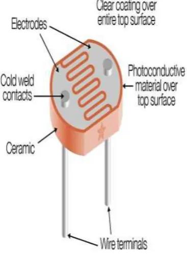
2.2.3: Light Dependent Resistor
It is a variable resistor whose value decreases with increasing incident light intensity. An LDR is made of a high resistance semiconductor, often cadmium-sulphide. If light falling on the device is of high enough frequency, photons absorbed by the semiconductor give bounded electrons enough energy to jump into the conduction band. The resulting free electron (and its whole partner) conduct electricity, there by lowering resistance. For sensing the sun light we mount the photo sensor on the top of the solar seeker/panel.
[image:3.595.312.562.325.596.2]Photo sensor senses the light and provide signal to the microcontroller. If the light is sufficient then LDR provide a signal to the microcontroller and microcontroller signals to stop the motor at this position. LDR used in Solar Panel Circuit. We have installed two LDR's in the circuit one is used for detecting the correct position perpendicular to sunlight and instruct the microcontroller to stop the solar panel at the position of maximum sunlight and the other one used for detecting whether it's a day or night and light the LED's accordingly.
Fig. 2.2.3: Light Dependent Resistor
2.2.4: Photovoltaic Cell
[image:3.595.87.271.458.708.2]The sun tracker uses a photovoltaic cell for light detection. Photovoltaic cells are devices that directly produce electricity from sunlight. Many photovoltaic cells are assembled together to form a solar array also known as solar panel. These cells convert light into electricity by converting energy resulting from photons from sunlight knock electrons into a higher state of energy, within the cell itself. Photovoltaic cells are composed of layered materials that include two types of silicon, an anti-reflective coating and a glass cover. Absorption of a photon by a semiconductor generates a pair of electron hole when its energy is higher than that of the prohibited bandwidth of material. The internal electric field with the junction, then involves the hole towards the area P and the electron towards the area N. By din of the semi-conductor of area of type P and N, the solar cell is thus a junction P-N with various parts represented on the diagram.
Fig. 2.2.4: Photovoltaic Cell
© 2019, IRJET | Impact Factor value: 7.211 | ISO 9001:2008 Certified Journal | Page 169
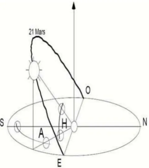
2.3: Position of Sun
Any solar application requires knowledge of the apparent movement of the sun for a given point of the earth surface, which is characterized by its latitude (positive for the northern hemisphere) and longitude (defined relative to the Greenwich meridian, positive eastward).The angular coordinates of the sun represent the apparent direction of the sun on its trajectory, for a fixed observer on the Earth, in a given moment. These coordinates are expressed in azimuth and height, respectively noted A and H. The azimuth A is the angle of the sun azimuth plane with the meridian plane of the place forms, if one defines the azimuth plane of the sun like the vertical plane (orthogonal to the local horizontal plane) containing the presumed specific sun and the point of observation.
The azimuth is measured starting from the direction of the South (azimuth 0 or solar midday - the sun passes in the meridian line of the place), positively towards the West and negatively towards the East. The height H of the sun is the angle, which forms the apparent direction of the sun with the horizontal plane of the place in the azimuth plan of the sun. It varies between the height at sunrise and sunset (intersection of the place horizontal plane with the celestial sphere) and the maximum height, depending on the latitude of the observation.
The variables considered are the latitude, which depends on the place, the variation which depends on the day and the time angle. During the day, the moment when the sun passes by the meridian line of the place of the observer, i.e. where it is in the south in our hemisphere is “true” midday. For one unspecified moment, time angle AH is the angle, projected in the field of the equator between the sun and true midday; it is worth 15° par hour (360°/24:00). It is null at solar midday the true (12h TSV), negative morning (-90° to 6:00 TSV), positive the afternoon (-90° to 18:00 TSV).
[image:4.595.315.555.83.353.2]Several parameters can be calculated such as the apparent direction of the sun for the moment, the day and the place considered, the height to midday and the azimuth with the sunrise and sunset for the day and the considered latitude as well. These three last data are sufficient to determine the apparent day trajectory of the sun and the latitude. They indeed allow determining three points on the celestial sphere (sunrise, culmination and sunset) which are enough with the geometrical or analytical characterization to the circular trajectory to the sun for the day and the considered latitude.
Fig. 2.3: Azimuth A and Height H of Sun
3. CIRUIT DESCRIPTION
3.1: Proposed System
While tracking sunlight, various methods and therefore different components may be used. In this work, the main components used are solar panel, 8051 microcontroller, DC motor, LDR, L293D motor driver IC.
3.1.1: Light Dependent Resistor (LDR)
In an LDR or Light Dependent Resister the intensity of light and resistance are inversely related, when the light intensity is the maximum, resistance is minimum and vice-versa. The programming is being done in simple C language. Thereafter, software namely Topwin is used to convert the code in Hexa Decimal form.
3.1.2: Microcontroller
© 2019, IRJET | Impact Factor value: 7.211 | ISO 9001:2008 Certified Journal | Page 170
3.1.3: L293 D
This is a motor driver IC in which half H driver with quadruple high current is designed for controlling two motors at a time. It provides drive currents of 600 mA that are bi-directional and the value of voltage is in the range of 4.5v - 36v.
3.1.4: DC Motor
[image:5.595.41.284.284.489.2]A permanent DC motor whose speed is reduced by means of a gear box is employed. Thus, Gear box reduces the speed of the moving platform. The 6-9 volts DC supply is given to this DC motor. When voltage is varied the speed of the DC motor also varies. The current drawn by the motor is 200 mA. The DC motor may be replaced by a stepper motor.
Fig. 3.1.4: Complete Hardware Module of Sun Tracking Solar Panel
However, the current consumption of a stepper motor is higher in comparison to a DC motor. In general, a stepper motor requires minimum 1A current. The complete hardware module of sun tracking solar panel is shown in fig. 3.1.4
3.2: Advantages of Sun Tracking Solar Panel
a) The solar energy can be reused as it is non renewable resource.
b) This also saves money as there is no need to pay for energy used.
c) Trackers generate more electricity than their stationary counterparts due to increased direct exposure to solar rays. This increase can be as much as 10 to 25% depending on the geographic location of the tracking system.
3.3: Disadvantages of Sun Tracking Solar Panel
a) Solar trackers are slightly more expensive than their stationary counterparts, due to the more complex technology and moving parts necessary for their operation.
b) Even with the advancements in reliability, there is generally more maintenance required then a traditional fixed rack, though the quality of the solar tracker can play a role in how much and how often then maintenance is needed.
c) Trackers are a more complex system than fixed racking. This means that typically more site preparation is needed, including additional trenching for wiring and some additional grading.
d) Single-axis tracker projects also require and additional focus on company stability an bankability. When it comes to getting projects financed, these system are more complex and thus are seen as a higher risk from a financier’s viewpoint.
e) Solar trackers are generally designed for climates with little to no snow making them a more viable solution in warmer climates. Fixed racking accommodates harsher environmental conditions more easily than tracking systems.
3.4: Applications of Sun Tracking Solar Panel
a) These panels can be used to power the traffic lights and streetlights.
b) These can be used in home to power the appliances using solar power.
c) These can be used in industries as more energy can be saved by rotating the panel.
4. CONCLUSION
© 2019, IRJET | Impact Factor value: 7.211 | ISO 9001:2008 Certified Journal | Page 171
possible to employ more photo sensitive resistors and useanother motor to rotate the panel in Sun’s direction according to seasons. This may further enhance the efficiency of the proposed Sun tracker. If two motors are used the tracker may give very high efficiency throughout the year.
5. ACKNOWLEDGMENT
We take this opportunity to express our gratitude and indebtedness to our guide Mr. M. J. Nemade, Assistant Professor, Electrical (E & P) Engineering department, who has been constant source of guidance and inspiration in preparing this paper.
REFERENCES
[1] Zahedi, "Energy People Environment Development of an
integrated renewable energy and energy storage system an uninterruptible power supply for people and for better environment", The International Conference on Systems Man and Cybernetics 1994. ‘Humans Information and Technology’, vol. 3, pp. 2692-2695, 1994.
[2] R. Singh, Y.R. Sood, "Transmission tariff for restructured
Indian power sector with special consideration to promotion of renewable energy sources", The IEEE Conference TENCON-2009, pp. 1-7, 2009.
[3] J. Arai, K. Iba, T. Funabashi, Y. Nakanishi, K. Koyanagi, R.
Yokoyama, "Power electronics and its applications to renewable energy in Japan", The IEEE Circuits and Systems Magazine, vol. 8, no. 3, pp. 52-66, 2008.
[4] S. Takemaro, Shibata Yukio, "Theoretical Concentration
of Solar Radiation by Central Receiver Systems", The International Journal of Solar Energy, pp. 261-270, 1983.
[5] S. Armstrong, W.G Hurley, "Investigating the