© 2019, IRJET | Impact Factor value: 7.211 | ISO 9001:2008 Certified Journal | Page 2000
Finite Element Analysis of New Circular Lateral Bracing System: A
Parametric Study
Sreekutty S
1, Binu P
21
Post Graduate student, Department of Civil Engineering, Sree Narayana
Gurukulam College of Engineering, Ernakulum, Kerala, India
2
Associate Professor, Department of Civil Engineering, Sree Narayana
Gurukulam College of Engineering, Ernakulum, Kerala, India
---***---Abstract -
Constructions are subjected to seismic lateralforces in seismically active zones besides the primary load of gravity. During an earthquake, the performance of a structure depends on the intensity of the seismic load, structural, geometrical characteristics etc. For good seismic performance of buildings, the use of an appropriate structural system is critical. Many engineers have been using innovative earthquake resistant structural systems in recent years to provide rigidity and ductility so as to prevent damage concentrations. Braced frames are one of the most widely used methods of building a lateral force resistant system with cost effectiveness and efficiency. The circular bracing system which is recently developed model is a braced system with a circular brace attached to the frame. Studies have shown that the energy dissipation of the new circular bracing systems is comparatively more efficient in performance than the frame and bracing models that are moment resisting. Parametric study of new circular bracing system is done using Finite Element Analysis software ANSYS 16.2.
Key Words: (Size 10 & Bold) Key word1, Key word2, Key word3, etc (Minimum 5 to 8 key words)…
1. INTRODUCTION
Steel structures are clearly a standout amongst the most widely recognized decisions for private structure developments in the world. In seismically active zones, besides carrying the primary gravity load, structures are subjected to lateral earthquake forces. Steel moment resistant frames during severe earthquakes are susceptible to large lateral displacements. Earthquake-resistant buildings should have at least a minimum lateral stiffness, so that during small shaking levels they do not swing too much. The flexibility of moment-resistant steel frames under strong ground movement can result in large lateral drift-induced non-structural damage. For good seismic performance of buildings, the use of an appropriate structural system is critical. Over the past few years, a large number of engineers have turned to the use of novel earthquake-resistant structural schemes to provide rigidity and ductility. Braced frames are the most widely used method of building lateral load resistant
system. Braced frames are cost effective structures for lateral load resistance.
D.C. Rai et al. (2003) [1] conducted an analytical seismic behavior study of "ordinary" concentrated braced steel frame structures to withstand upcoming earthquakes. Development can be attained by converting the brace and beam into a frail brace and a strong beam system. R. Tremblay et al. (2003) [6] carried out an investigational study on the seismic behavior of concentrated steel frames made of cold shaped rectangular tube-shaped bracing elements. Simplified models are proposed as a function of the ductility level to predict the brace out - of - plane deformation. Seismic reaction analysis of braced frames making use of buckling-controlled braces was conducted by R. Sabelliet al. (2003) [5]. F. Ferrario et al. (2016) [2] carried out studies on circular steel hollow columns made of high strength steel subject to exceptional loads, such as earthquakes. Bracing weakening through adequate web holes seems to be a sufficiently acceptable design solution to ensure sufficient structural behavior. In order to improve the behavior of ordinary seismic load resistant steel buildings, Niloufar Mashhadiali et al. (2018) [4] suggested a novel braced steel frame called hexagonal - braced steel frame. Maryam Boostani et al. (2018) [3] investigated experimentally and analytically the seismic performance of newly developed circular shaped bracing systems. The new bracing system's linear and nonlinear behavior was analyzed and compared to X-shaped bracing system and moment - resistant frame. From the results, the energy absorption of the new bracing systems was more compared to the moment - resistant frame, and much superior compared to the X-shaped bracing model. The circular bracing system's behavior with I-shaped brace was obtained to be better than those with H shaped brace sections.
© 2019, IRJET | Impact Factor value: 7.211 | ISO 9001:2008 Certified Journal | Page 2001
in this paper. Objectives of this study was to conductparametric study on circular bracing system.
2. NUMERICAL MODELLING AND ANALYSIS OF
CIRCULAR BRACING SYSTEM
Circular bracing system has a circular shaped brace attached to a steel frame. The beam, column and brace cross-sections are steel I sections. The length of column and beam was taken as 3000 mm and 2820 mm. Based on the brace element shape utilized, the circular bracing system was named as OGBI. For simplification, Circular bracing model with I section brace was named as OGBI. Numerical modeling of circular OGBI base model was done using ANSYS 16.2 WORKBENCH. Material property for the model was selected from engineering data section of the software, where all the available materials are pre-assigned with default value for various properties as shown in Table 1. For every parameter investigation, the circular OGBI base model was kept as a reference model for comparison.
[image:2.595.308.561.143.390.2]
Table -1: Material Properties of Steel
Density = 7850 kg/m3
Modulus of Elasticity = 2 x 10⁵ N/mm2
Poisson’s Ratio = 0.33
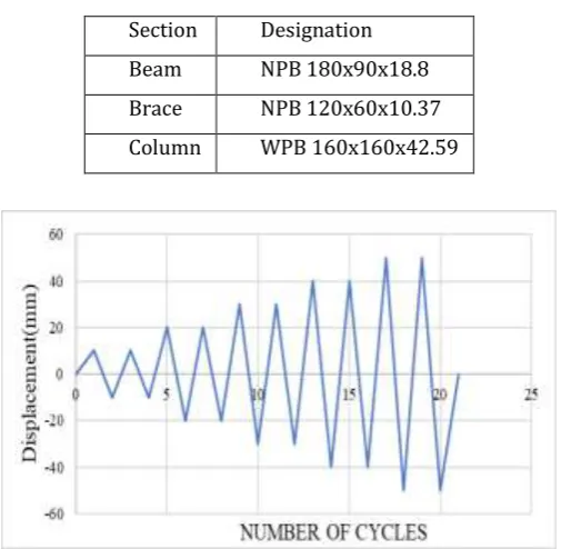
[image:2.595.45.279.377.449.2]For braces and beams, Indian Standard NPB sections and for columns, WPB standard sections were used as per IS 12778:2004, which are shown in Fig. 1 and Table 2.
Fig -1: Section details of OGBI base model
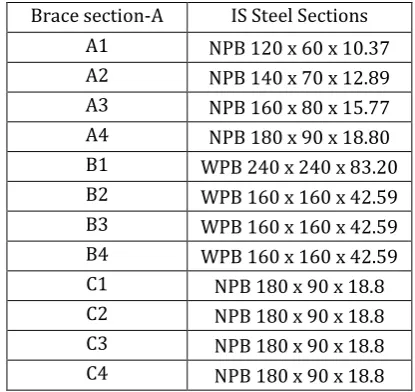
Geometry of OGBI base model was sketched in workbench window. Material properties were assigned to the model as mentioned in the Table 1. OGBI base model after modelling, the support condition and loading were given. All joints in the OGBI model are assumed rigid to represent the directly welded connection between the members. The fixed support was given at the bottom of columns and then loading was given at top. The cyclic loading program was written with the help of the displacement obtained after applying monotonic loading. The cyclic loading program was adopted as per specifications of ATC 24. The cyclic loading program adopted has 26 cycles. The loading protocol is given in the
Fig. 2. With help of ANSYS software, the cyclic loading was given to analyze the behavior of OGBI base model.
Table -2: Section designations of OGBI base model
Section Designation Beam NPB 180x90x18.8 Brace NPB 120x60x10.37 Column WPB 160x160x42.59
Fig -2: Cyclic loading program for OGBI base model
3. PARAMETER STUDIES ON CIRCULAR OGBI
BRACING MODELS
The parametric studies were conducted on OGBI bracing models. The key parameters studied include type of support conditions, type of steel sections of column, dimensions of steel sections. The influence of each parameter on the behavior of the circular bracing system was studied. For every parameter investigation, the OGBI base model is kept as a reference model for comparison.
3.1. Type of Support Condition
Supports are arguably one of the most important aspects of a structure, as it specifies how the forces within the structure are transferred to the ground. This knowledge is required before solving the model, as it tells us what the boundary conditions are. Supports are crucial parts of a structural analysis model. The different types of supports commonly used are fixed Support, pinned Support and roller Support. The support condition of OGBI base model was fixed. The support condition studied was pinned condition.
[image:2.595.39.283.503.590.2]© 2019, IRJET | Impact Factor value: 7.211 | ISO 9001:2008 Certified Journal | Page 2002
Fig -3: Cyclic loading program for OGBI model with pinnedsupport condition
3.2. Shape of Column Steel Section
The column of OGBI base model was of I-shaped steel section. Hollow steel section for column was studied and compared with OGBI base model. 300 x 300 x 6.3 mm (SHS) square steel hollow section was selected for column. After modelling, the uniform meshing was given for the model. After monotonic loading, the Displacement vs force curves were obtained. With help of the displacement obtained, cyclic loading program was written for the model. Cyclic loading program was adopted as per the specifications of ATC 24, shown in Fig. 4. The cyclic loading adopted has 26 cycles.
Fig -4: Cyclic loading program for OGBI model with hollow section column
3.3. Cross-sectional Dimensions of Steel Sections
The influence of changing the beam section, column section and brace section on the cyclic behavior of the OGBI bracing system and to achieve the maximum efficiency of the total system including beam, columns, and brace to extract their effective and useful stiffness ratios was studied.10 models have been selected through changing the brace section or the beam section or the column section. Designations of models were based on the beam, column and brace types used in models. Sections
[image:3.595.329.537.441.637.2]include four types of beams, four types of columns, and four types of braces.
Table -3: Details of OGBI models with different steel sections
Models Brace
section-A section-B Beam section-C Column
OGBI-A1-B1-C1 A1 B1 C1
OGBI-A1-B1-C2 A1 B1 C2
OGBI-A1-B1-C3 A1 B1 C3
OGBI-A1-B1-C4 A1 B1 C4
OGBI-A1-B2-C1 A1 B2 C1
OGBI-A1-B3-C1 A1 B3 C1
OGBI-A1-B4-C1 A1 B4 C1
OGBI-A2-B1-C1 A2 B1 C1
OGBI-A3-B1-C1 A3 B1 C1
OGBI-A4-B1-C1 A4 B1 C1
Details of the models were described in Table 3 and details of the sections are given in Table 4. Indian Standard NPB sections have been used for braces and beams and WPB sections for columns. The bracing systems were modelled using ANSYS program.
Table - 4: Details of steel sections
Brace section-A IS Steel Sections A1 NPB 120 x 60 x 10.37 A2 NPB 140 x 70 x 12.89 A3 NPB 160 x 80 x 15.77 A4 NPB 180 x 90 x 18.80 B1 WPB 240 x 240 x 83.20 B2 WPB 160 x 160 x 42.59 B3 WPB 160 x 160 x 42.59 B4 WPB 160 x 160 x 42.59 C1 NPB 180 x 90 x 18.8 C2 NPB 180 x 90 x 18.8 C3 NPB 180 x 90 x 18.8 C4 NPB 180 x 90 x 18.8
[image:3.595.36.289.446.596.2]© 2019, IRJET | Impact Factor value: 7.211 | ISO 9001:2008 Certified Journal | Page 2003
Fig -5: Cyclic loading program for OGBI models withdifferent steel sections
4. RESULTS AND DISCUSSIONS
Static analysis of circular bracing systems with cyclic loading was done using ANSYS 16.2 WORKBENCH. In static analysis, the hysteresis responses and energy absorption capacities of circular bracing systems were obtained. The effect of parameters such as support condition, steel section of column and cross-sectional dimensions on performance of circular bracing systems were studied.
4.1. Hysteresis Response of Circular OGBI Base
Model
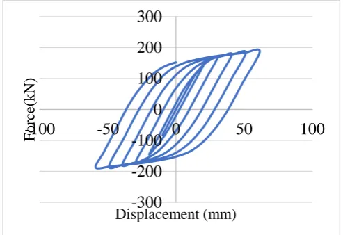
From the ANSYS 16.2 WORKBENCH, hysteresis curve for OGBI base model was obtained. The chart 1 shows the hysteresis curve of OGBI base model obtained after static structural analysis of the model. The obtained curve was a smooth loop. The area enclosed by loop gives the energy absorption capacity of the model.
-300
-200
-100
0
100
200
300
-100
Fo
rce(
-50
0
50
100
k
N
)
Displacement (mm)
Chart -1: Hysteresis curve obtained for OGBI base model
4.2. Energy Absorption of Circular OGBI Base
Model
The energy dissipation was illustrated by the hysteretic area obtained from the analysis, which was measured by the load displacement diagram as the enclosed area. OGBI model have dissipated a sufficient amount of energy. OGBI model have energy dissipation value of 36.70 kJ.
4.3. Effect of Type of Support Condition
The hysteresis curve was obtained for OGBI model with pinned support condition after the static analysis. Chart 2 shows comparison of hysteresis curves of OGBI model with fixed support and pinned support condition.
-300 -200 -100 0 100 200 300
-100 -50 0 50 100
F
o
rce(
k
N)
Displacement (mm)
pinned fixed
Chart -2: Comparison of hysteresis curve of OGBI models with fixed and pinned support condition
From the chart, it was clear that model with fixed support have a wider loop than the model with pinned support condition. It can be inferred that the model with fixed support condition have more energy absorption capacity compared to model with pinned support condition.
The area under the hysteresis curve gives the energy absorption. From the results, we can infer that the energy absorption of OGBI model decreased by changing fixed support condition to pinned support condition. Energy absorption value of OGBI model with pinned support was 15.303 kJ, which was 58.3% less than OGBI model with fixed support condition.
The stiffness of OGBI bracing systems was calculated from hysteresis curves using the stiffness formula,
Stiffness = (F max – F min)/ (d max – d min)
© 2019, IRJET | Impact Factor value: 7.211 | ISO 9001:2008 Certified Journal | Page 2004
kN/mm which is 47.89% less than the model with fixedsupport condition.
3.4. Effect of Type of
S
teel Sections of Column
Hollow steel section for column was studied and compared with OGBI base model. Load vs displacement hysteresis response of OGBI model with hollow steel column was obtained from ANSYS. Chart 3 shows the comparison of hysteresis curves of OGBI model with I section and hollow section columns.
Chart -3: Comparison of hysteresis curve of OGBI models with I section and hollow section columns
The area under the hysteresis curve gives the energy absorption. From the results, we can infer that the energy absorption of OGBI model with I-section column was more than the model with hollow section column. Energy absorption value of OGBI model with hollow section column was 32.782 kJ, which was 10.68% less than OGBI model with I-section column.
The stiffness of OGBI bracing systems with different column sections are calculated from hysteresis curves using the stiffness formula,
Stiffness = (F max – F min)/ (d max – d min) The stiffness of OGBI model with I-section column is 2.61 kN/mm. The stiffness of OGBI model with hollow section column was 4.08 kN/mm, which was 36.02% more than OGBI model with I-section column.
3.5. Effect of Cross-sectional Dimensions of Steel
Sections
Chart 4, chart 5 and chart 6 shows the comparison of hysteretic curves of OGBI models with changes in brace section, beam section and column section respectively. From the chart, it was clear that hysteresis loops become wider with increase in cross-sectional size of the brace member. But with increase in the cross-sectional size of beam members, there was only a slight increase in the
area of the hysteresis loop of the models. The hysteresis loops also become wider with increase in cross-sectional size of the column member.
Chart -4: Comparison of hysteresis curve of OGBI models with brace section increase
-200 -100 0 100 200
-100 -50 0 50 100
Fo
rce
(k
N)
Displacement(mm)
BM OGBI-A1-B2-C1
OGBI-A1-B3-C1 OGBI-A1-B4-C1
Chart -5: Comparison of hysteresis curve of OGBI models with beam section increase
© 2019, IRJET | Impact Factor value: 7.211 | ISO 9001:2008 Certified Journal | Page 2005
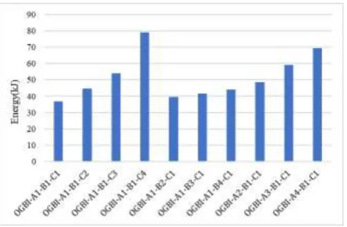
The area under the hysteresis curve gives the energyabsorption. Chart 7 shows the comparison of energy absorption values of OGBI values with changes in section dimensions.
Chart -7: Comparison of energy absorption values of OGBI with different section dimensions
We can infer that the energy absorption of OGBI model increases by increasing the member section dimension. Energy absorption values of the models was given in Table 5.
The stiffness of OGBI with different section dimensions were calculated from hysteresis curves using the stiffness formula,
Stiffness = (F max – F min)/ (d max – d min) The stiffness values of the models are given in Chart 8 and Table 6. It is observed that stiffness values of the models increase with increase in section dimensions.
Table - 5: Energy absorption values of OGBI with different section dimensions
Models Energy absorption Values (kJ)
OGBI-A1-B1-C1 36.70
OGBI-A1-B1-C2 44.78
OGBI-A1-B1-C3 54.00
OGBI-A1-B1-C4 79.01
OGBI-A1-B2-C1 39.40
OGBI-A1-B3-C1 41.51
OGBI-A1-B4-C1 44.10
OGBI-A2-B1-C1 48.47
OGBI-A3-B1-C1 59.20
OGBI-A4-B1-C1 69.37
[image:6.595.305.562.53.237.2]Chart -7: Comparison of stiffness values of OGBI with different section dimensions
Table - 6: Stiffness values of OGBI with different section dimensions
Models Stiffness (kN/mm)
OGBI-A1-B1-C1 2.61
OGBI-A1-B1-C2
3.08
OGBI-A1-B1-C3
3.59
OGBI-A1-B1-C4
4.13
OGBI-A1-B2-C1
2.70
OGBI-A1-B3-C1
2.78
OGBI-A1-B4-C1
2.89
OGBI-A2-B1-C1
3.09
OGBI-A3-B1-C1
3.65
OGBI-A4-B1-C1
5.08
5. CONCLUSIONS
The strength behavior of circular bracing systems under cyclic loading was studied using numerical analysis. The influence of parameters on circular bracing systems were also studied. The following are the conclusions derived from the studies conducted:
Energy Absorption and stiffness of circular bracing model with fixed support was more when compared with pinned support.
Stiffness of circular bracing model increases when hollow section was used for column.
Circular bracing models shows improved results in energy absorption and stiffness with increase in cross section of the members.
[image:6.595.37.289.150.315.2]© 2019, IRJET | Impact Factor value: 7.211 | ISO 9001:2008 Certified Journal | Page 2006
REFERENCES
[1] D.C. Rai a, S.C. Goel. “Seismic evaluation and upgrading of chevron braced frames” Journal of Constructional Steel Research, 2003, 59: 971–994
[2] F. Ferrario, F. Iori, R. Pucinotti, R. Zandonini. “Seismic performance assessment of concentrically braced steel frame buildings with high strength tubular steel columns” Journal of Constructional Steel Research 2016, pp.121: 427–440,
[3] Maryam Boostani, Omid Rezaifar, Majid Gholhaki. “Introduction and seismic performance investigation of the proposed lateral bracing system called OGrid” archives of civil and mechanical engineering, 2018, pp.1024-1041
[4] Niloufar Mashhadiali, Ali Kheyroddin. “Seismic performance of concentrically braced frame with hexagonal pattern of braces to mitigate soft story behavior” Engineering Structures, 2018, pp.175: 27– 40
[5] R. Sabelli, S. Mahin b, C. Chang. “Seismic demands on steel braced frame buildings with buckling restrained braces” Engineering Structures, 2003, pp.25: 655–666, [6] R. Tremblay; M.-H. Archambault; and A. Filiatrault. “Seismic Response of Concentrically Braced Steel Frames Made with Rectangular Hollow Bracing Members” Journal of Structural Engineering, ASCE, 2003, pp.129:1626- 1636
[7] ATC 24 – Guidelines for Cyclic Seismic Testing of Components of Steel Structures.