Double Block-based Improved Copy-Move Forgery
Detection
Aspira S. Tripathy
NSIT
Dwarka, Sector-3
Delhi-78
Vikas Maheshkar
NSIT
Dwarka, Sector-3
Delhi-78
ABSTRACT
With the advancement of handy and sophisticated image editing software, the alteration of digital images‟ contents has become rife in all senses and camouflaged enough for non-identification. A digital image is a copious source of data and information that can be used for corroboration of factual events; however, in the recent times, its authenticity has developed a questionable background. Various types of forgery have come into picture within the past years. To counteract these forgeries, equal efforts have been focused on to make systems, inclusive of techniques to detect the forgeries. Keeping the accuracy, precision and the time complexity in mind, this paper focuses primarily on Discrete Cosine Transformation Block Based Copy-Move Forgery detection technique. The algorithm evaluation using blocks of sizes 8x8 and 16x16 are compared and contrasted to get a vivid idea about the advantages and shortcomings of using either of these. 8x8 blocks detect even the slightest tampering accurately, due to the small size of blocks, but yield a large number of false matches. Whereas, 16x16 blocks significantly reduce the number of false matches, but also the accuracy since now the minute forgeries aren‟t detected. The information, thus received, has served as grounds in this paper to provide an improved algorithm, which combines the advantages of both the parts and then renders better results, comparatively.
General Terms
Image Forensics, Copy Move Forgery, Image Processing
Keywords
DCT, Copy move forgery detection, Image processing, Image Forensics, Block based forgery detection, image tampering, passive forgery detection.
1.
INTRODUCTION
Imitations are not unfamiliar to humanity but rather a quite old issue. In the past it was restricted to artistry, writing and craftsmanship, yet did not influence the overall population. These days, however, the headway of computerized image handling software and altering devices, have made it quite facile for the common population to remold images [1]. Consequently, the problem of determining whether the picture is unique or manipulated has burgeoned as a prime issue and therefore, there is fast increment in digitally controlled falsifications on the Internet and the standard media [2]. All of us are quite aware of a well-known idiom, which states, “A picture is worth a thousand words”. Tampering of images, which have profuse applications in various existent domains starting from newspaper articles to evidences provided in formal court, are extensively done using numerous techniques, namely Image Splicing, Image Retouching and Copy-Move Forgery. The latter is the most challenging forgeries of all, since it incorporates forgery of a particular area from within a segment of the original image and
therefore, image properties such as image texture, dynamic range and color palette remain compatible throughout the image. This is one of the major reasons of ever-advancing research in copy-move forgery detection, which includes majorly two approaches: Block Based Forgery Detection and Key-point Based Forgery Detection. Tampering with the images leads to deviation from the purpose of images where the authenticity of images is the most important factor of all. Image tampering is arguably a digital art, which needs one to comprehend the image properties well. Additional post-processing techniques are also made use of, the majority of time for camouflaging, aptly, the alterations. For example, in case of Copy-move forgery, the imitative region may not be the precise copy or the originally cropped portion, when pasted [3]. The post-processing of a tampered image is usually done to delete signs of alterations up to a certain level and apparent suspicions that makes it incomprehensible by the naked eye of a person
Figure 1. Various image forgery detection techniques
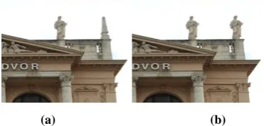
Out of the tampering techniques stated above, whereas Image Splicing and Image Retouching lead to a difference in the intrinsic image properties between the forged region and the rest of the image, copy-move forgery is a kind that does not segregate it on this basis. It is a special type of image manipulation technique in which a part of the image itself is cloned, moved to a desired segment within the image and pasted [10]. This type of forgery is also known as Cloning-type of forgery and is usually used to conceal an informative portion of the image, which might be important in some means, by superimposition [11]. Any Copy-Move forgery leads to the introduction of specific correlation between the original image segments and the pasted ones. An example of Copy-Move Forgery is given in Figure 2, where a statue from within an image is used in order to conceal the vertical structure on top. This image has been taken from the CoMoFod Dataset of 100 copy-move forged images. Image Splicing refers to combination of two or more parts of images or images as whole, which significantly change the original image [9]. Image Retouching is done only to enhance or limit certain features of the image and is one of the most common image tampering methods used due to expedient access to image editing tools and software. This paper focuses on Copy-Move forgery only and presents an improvement on the basis of accuracy and precision, using the usual DCT implementation with an incorporated modification. For this, two different types of block-sizes are used and the cumulative effect has been recorded.
The rest of the paper is oriented according to 4 pellucid sections. Section 2 gives a brief review of the basics of DCT along with previous related research work within the field, Section 3 provides the proposed detection algorithm in detail, Section 4 presents the experimental results and analysis and the paper is concluded, in Section 5.
[image:2.595.73.259.633.722.2](a) (b)
Figure 2. An Example Of Copy-Move Forgery
2.
DCT AND RELATED WORK
2.1
Discrete Cosine Transform (DCT)
Discrete cosine transform (DCT) is a mathematical transformation method, which reworks every pixel of an image in the spatial domain into DCT coefficients in the frequency (transform) domain. Quite significant to various applications in engineering and science, from lossy compression of images (e.g. JPEG) and audio (e.g. MP3) to spectral techniques for solving partial differential equations, its domain extends broadly across sectors [12]. It has numerous properties such as symmetry, de-correlation etc. out of which “energy compaction” is particularly of great significance in the field of digital signal and image processing [12]. It segments images into components of varying frequencies. Due to this specific property of energy compaction, the maximum signal information is stored in the low-frequency components and the higher frequencies represent the components of an image with minute intrinsic information. The high-frequency coefficients of DCT are generally equal to zero and do not contribute much towards the formation of the image. On the other hand, the major information is concentrated in the top-leftmost coefficient (also known as DC or the average coefficient), which has the highest value. Two-dimensional DCT has the following equation:𝐷 𝑖, 𝑗
= 1
2𝑁𝐶 𝑖 𝐶 𝑗 𝑝 𝑥, 𝑦 cos
2𝑥 + 1 𝑖𝜋 2𝑁 cos
2𝑦 + 1 𝑗𝜋 2𝑁
𝑁−1 𝑦 =0 𝑁−1 𝑥=0
𝐶 𝑢 = 𝑓 𝑥 = 1
2, 𝑢 = 0 1, 𝑢 > 0
p(x,y) is the x, y element of the image matrix p, which consists of image information. N represents the block-size on which DCT is done. This equation calculates one item of the transformed image (i.e. one DCT coefficient) from the original image matrix. From the equation, it is quite evident that on x=y=0, the cosine terms become one and the periodic terms vanish. This bolsters the fact that the left-topmost coefficient is known as the DC coefficient and the rest are known as AC coefficients.
𝐷𝐶𝑐𝑜𝑒𝑓𝑓 = 𝐷 𝑖, 𝑗 =
1
2𝑁 𝐶 𝑖 𝐶 𝑗 𝑝(𝑥, 𝑦)
𝑁−1 𝑦 =0 𝑁−1 𝑥=0
2.2
Related Work
Several methods have been existent through the past years and developed as well, to detect copy-move forgeries. There are two major methods used for forgery detection: Block Based methods and Key-point Based methods. Both methods have been sufficiently evaluated and used in various papers for accurate detection. However, the simplest approach is dividing the image into overlapping blocks of small fixed size and searching exhaustively for disparity identification between block pairs, comparing their pixel intensity values. Then an upper bound threshold could be applied for matching, or lower bound threshold for differences to categorize two pairs as copy-move forgery pairs
.
Fridrich et al first proposed this in their paper [7]. They used blocks of 16x16, to avoid large number of false matches by 8x8 blocks. They described the exhaustive search indicating about its bounded applicability, which was circumscribed by the exponential run-time complexity, and the fact that any distortion rendered it useless. Further, in the same paper, they highlighted towards a comparatively efficient approach, and an advancement to theIMAGE FORGERY DETECTION TECHNIQUES
PASSIVE APPROACH
ACTIVE APPROACH
Digital Watermarking
Digital Signatures
Independent Dependent
Image Splicing Copy-Move
exhaustive search method described, which made use of quantized discrete cosine transform (DCT) coefficients for robust representation of features of the blocks. Propescu [13] searched similar blocks using feature extraction method of the principle of component analysis (PCA), instead of DCT. Luo et al [14] extracted spatial intensity ratios and color features to represent block characteristics‟ features. This method also incorporated the post-processing done on images, such as noise contamination, blurring etc. Hu et al. [15] proposed an even improved algorithm based on DCT, on grounds of accuracy and robustness. For this, blocks of size 8x8 pixels were used. DCT was applied to every block and the transformed coefficients were quantized using the generic quantization table of JPEG compression. Zigzag scan fashion was implemented to group the similar frequencies of DCT coefficients together. Lexicographic sorting was carried out and the eigenvectors were computed for each row vector. Kumar et al [16] worked on the same lines and proposed a faster method on DCT by reducing the dimensions of the feature vectors, by truncating to retain only low frequency components, and hence the time complexity. This method, however, did not work for noisy images and missed out on many intermediate frequency values. Kang et al [18] used Singular Value Decomposition (SVD) and detected copy-move forged areas in an image. Li et al [17] introduced a novel combination of a transformation and a decomposition method. They compared each block pair using discrete wavelet transformation (DWT) and singular vector decomposition (SVD). Lin et al [19] proposed a faster method using double quantization DCT, which worked however only for JPEG formats. Hao et al [20] used the matrix dimensionality reduction technique of Non-Negative Matrix Factorization to reduce the dimensions of the feature vectors obtained and robust matching. However, some geometric distortions rendered the method invalid. Phase correlation was also made use of, which worked fine even with additive noise and blurring effects, in the paper by Xu et al [21]. Further, cluster analysis methods were used by Yu et al. [22] to analyze the DCT coefficients of image blocks. This method was effective in detecting copy-move forgeries and resisting post-processing operations, such as adding white Gaussian noise, and JPEG compression in digital images. However, it didn‟t work well when tampered images underwent mixed operations of the various types of post-processing techniques. For achieving rotational, translational and scaling invariance, Bayram [23], used Fourier-Mellin transform (FMT). The FMT values were ultimately projected onto single dimension using decomposition methods, forming the feature vectors. Mahdian [24] used blur invariant moments to locate forgery regions. Zhao [12] proposed an algorithm wherein the 8x8 blocks were further divided into 2x2 blocks and SVD was applied to each 2x2 block. This introduced a fusion of DCT along with SVD. The largest singular values were extracted from the 2x2 blocks and presented as row vectors for matching purpose. Huan [4] also introduced an efficient passive authentication method where pixel mean calculation was done parallel to DCT transformation and feature extraction steps. Sridevi [25] presented a parallel block matching technique that could reduce the run time of the algorithms proposed earlier. Amani [26] used DCT+LBP (Local Binary Pattern) to detect the forged areas within an image. Almost all the methods mentioned above come under the category of Block based detection methods. Much research is carried out using the key-point based technique as well. The key-point based methods, unlike the block based methods, focus more on the selection and identification of high-entropy image segments.
Huang et al [27] used SIFT (Scale Invariant Feature Transform) features to detect tampered regions, which was invariant to scaling, rotation and affine transformations. The algorithm however rendered a large number of false detections. The papers [28-29] also use the SIFT algorithm for detection. Following the two methods of DWT and SIFT, an algorithm was proposed by Hashmi et al [30] that combined the both. However, the number of false matches was also significant in this method. Alkawaz [3] in their paper compared the efficacy of the DCT based algorithm when the block sizes are varied, and carried out experiments for 4x4 as well as 8x8 blocks. The discovery methodology in DCT begins at the upper left corner, scanning towards the lower right corner while sliding a small sized block, say P x P. What makes the use of DCT desirable is its comparably higher accuracy rate. However, every method has some or the other shortcomings in its application. For example, if there are a large number of blocks, extract feature vectors‟ sizes from the blocks will increase, and thus, time complexity would shoot up. Smaller blocks will render minute variability in the coefficients and this would lead to higher probability of false positives [3], whereas larger blocks would sacrifice accuracy. The findings illustrated the fact that the smaller the size, the more the false positives and the lesser the time complexity. Therefore, there is always a trade-off between these two factors.
In this paper, the focus was on balancing the two factors, which rendered both, great accuracy in reasonable time complexity. It is an extension of the DCT based methods proposed earlier. The image is segregated using blocks of two sizes 8x8 and 16x16 and individual quantized DCT coefficients are extracted as row vectors. Lexicographic sorting is done and matching is performed. The proposed method works well with color adjustments/reduction, contrast changes, image blurring, background adjustments, and multiple copy-move forgeries within a single image. These images have been included in the experimental results and analysis section.
3.
DETAILED ALGORITHM
This section provides with the detailed algorithm along with each intermediate step explained explicitly. In this paper, higher accuracy and mean precision have been established by cascading of blocks for detection. By accuracy, proper identification of forged regions with minimal number of false matches is meant.
3.1
Proposed Schema
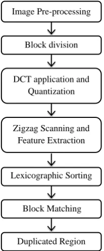
The algorithm works on the general course or framework of any copy-move forgery detection algorithm. A schematic flowchart is shown in Figure 3. The list of processes include: Image pre-processing, Division of image matrix into blocks of size N1 and N2, individual computation of quantized DCT coefficients for each size of block, Extraction of feature vectors, Lexicographic Sorting, Comparison and matching and Highlighting of duplicated regions. The internal structure of the above stated processes is explained in detail in Figure 3.
3.1.1
Image Pre-processing
If the image provided, suspicious of tampering, is an RGB image, it is first pre-processed into a gray-scale image by using the following formula:
I = 0.299R + 0.587G + 0.114B
is usually contained in the luminance plane and has little to do with the Chroma of an image. Therefore, the chrominance or color content of an image can be treated as „noise‟ or „unwanted information‟ for various signal processing applications.
Figure 3. Schematic flowchart of proposed algorithm
3.1.2
Block Division
The next step comprises of division of the input image matrix into blocks of two different sizes, 8x8 and 16x16. This constitutes the main part of the algorithm, which focuses on enhancing the accuracy by considering cascaded blocks in consequent processes. The block division is done in a sliding fashion so that two consecutive blocks differ by either one row or one column of pixels, from the left to the right corner. Thus, given an input image of N x M pixels and block size B, the total number of blocks would come out to be equal to (N – B + 1) x (M – B + 1). These blocks are stored in two different array matrices. For Example, let us consider the figure 5 shown below: a block of size 3x3 has been divided into blocks of size 2x2. Here, N = 3 and B = 2. Thus, the number of blocks is: (3-2+1) * (3-2+1) = 2*2 = 4
1 2 21
3 15
7 23
0 30
= 1 2 3 7 ,
3 7
15 23 , 2 21 7 0 ,
7 0
[image:4.595.328.511.264.348.2]23 30
Figure 4. Block division
3.1.3
DCT Application and Quantization
Once the division is done, sequential transformation of the 8x8 blocks and the 16x16 blocks into their DCT coefficients is done. The DCT conversion is speeded up by pre-computing the DCT matrix of pre-defined block size, and then using the formula shown, for computing the DCT coefficients of a B x B block.
𝐷𝐶𝑇𝑏𝑙𝑜𝑐𝑘 = 𝐷𝐶𝑇𝑚𝑎𝑡𝑟𝑖𝑥 ∗ 𝐵𝑙𝑜𝑐𝑘 ∗ 𝐷𝐶𝑇𝑚𝑎𝑡𝑟𝑖𝑥′
where 𝐷𝐶𝑇𝑚𝑎𝑡𝑟𝑖𝑥′ = 𝑡𝑟𝑎𝑛𝑠𝑝𝑜𝑠𝑒 𝑜𝑓 𝑡𝑒 𝐷𝐶𝑇𝑚𝑎𝑡𝑟𝑖𝑥
This gives us the DCT coefficient matrix of any block size within lesser time as compared to explicitly calculating the DCT for each block, as and when the block is retrieved. After
this transformation, a quantization matrix along with a user-defined Quality Factor is used to quantize the coefficients of the blocks. The Quality factor is used to determine the quantization steps for DCT transform coefficients. The lower the Quality Factor, the finer the quantization process is. That is, the image is scrutinized more closely for forgery and there is less number of false matches. Similarly, larger the quality factor, coarser the quantization and therefore, the number of false matches increases. The quantization matrix used for the 8x8 blocks is the standard JPEG quantization matrix. In [7], experimental results proved that all the harmonic coefficients for 16×16 blocks were 2.5 times larger, on an average, and the DC or average term was twice of that for 8x8 blocks. Therefore, this form of the quantization matrix was preserved and used in this paper as well, which is shown below. This quantization step concentrates the energy or entropy of the image in the few low frequency coefficients and nullifies the high frequency terms.
𝑄16= 2.5 ∗ 𝑞𝑄8′ 2.5 ∗ 𝑞18∗ 𝐼 81∗ 𝐼 2.5 ∗ 𝑞88∗ 𝐼
Where
𝑄8=
2 ∗ 𝑞00 2.5 ∗ 𝑞12
2.5 ∗ 𝑞21 2.5 ∗ 𝑞22
… 2.5 ∗ 𝑞18
… 2.5 ∗ 𝑞28
… …
2.5 ∗ 𝑞81 2.5 ∗ 𝑞82
… …
… 2.5 ∗ 𝑞88
[image:4.595.318.541.447.574.2]3.1.4
Zigzag Scanning and Feature Extraction
After proper quantization of DCT coefficients has been done, the feature vectors for each block are extracted and stored in row vectors. This is done with the aid of zigzag scanning as shown in Figure 5 [3]. Figure 5 demonstrates for an 8x8-sized block. The zigzag scanning pushes the zero values towards the end of the vector and therefore increases performance of algorithm. Two different matrices are maintained: for the 8x8 block features‟ vectors and the 16x16 block features‟ vectors.Figure 5. Zigzag scanning and feature extraction
3.1.5
Lexicographic Sorting
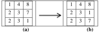
The feature vectors extracted are then sorted lexicographically for comparison. Both the sets of feature vectors, one for each size of block, are sorted separately. Feature row vectors of similar or matching blocks are juxtaposed using lexicographic sorting, which is done in order to reduce the time complexity, as now only the present and the immediate next is needed to be tested for percentage matching of the blocks. Therefore, the time complexity reduces from O (𝑛2)to O (n). Figure 6
shows the pre-sorting and post-sorting scenarios of the feature vectors‟ set assuming random intermediates.
Image Pre-processing
Duplicated Region Block Matching
Block division
DCT application and Quantization
Zigzag Scanning and Feature Extraction
1 4 8
2 3 7
2 3 1
1 4 8
2 3 1
2 3 7
(a) (b)
Figure 6. (a) Feature vectors (b) Sorted feature vectors
3.1.6
Block Matching
Once done with the sorting step, one can move on to compare the adjacent row vectors to identify copied and pasted blocks. This process is dealt separately for each kind of block. For matching of the 8x8 blocks, the Euclidean distance is calculated between the juxtaposed feature vectors extracted. The Euclidean distance is the shortest distance between any two points, (x1, y1) and (x2, y2) in a plane given by the formula below:
Euclidean distance =
(𝑥1− 𝑥2)2+ (𝑦1− 𝑦2)2 This is a measure of the closest approximation between any two points, and is used to find the variation between any two particular block pixel values. A preset threshold value is considered as a basis for suspecting the looked pair as a couple of possible forgery. If the Euclidean distance is lesser than this particular threshold, say 𝑇𝑒𝑢𝑑𝑖𝑠𝑡, it can be said that
the adjacent pairs are forged. The criteria for matching is shown below:
𝐸𝑢𝑐𝑙𝑖𝑑𝑑𝑖𝑠𝑡𝑎𝑛𝑐𝑒 = 𝑛=62𝑛=1 (𝑎𝑖𝑛− 𝑎𝑖+1𝑛 )2< 𝑇𝑒𝑢𝑑𝑖𝑠𝑡 (1)
In the above stated formula, ai= ith row vector and 𝑎𝑖+1=
(𝑖 + 1)𝑡row vector. Once the Euclidean distance between
adjacent pairs is known, one has to make sure that the reason behind this isn‟t that the blocks are too adjacent or in the immediate neighborhood. It is quite likely that the neighboring pixels have more or less the same values in an image unless there is a sharp edge or gradient, like for example, in a flat region. To take care of this, the minimum distance threshold, 𝐷𝑖𝑠𝑡𝑚𝑖𝑛, is pre-set. The blocks considered
being forged need to have a minimum distance between them in the original image, that is:
𝐷 = (𝑥𝑖− 𝑥𝑖+1)2+ (𝑦𝑖− 𝑦𝑖+1)2> 𝐷𝑖𝑠𝑡𝑚𝑖𝑛 (2)
𝑥𝑖= 𝑥 − 𝑐𝑜𝑜𝑟𝑑𝑖𝑛𝑎𝑡𝑒 𝑜𝑓 𝑠𝑡𝑎𝑟𝑡𝑖𝑛𝑔 𝑝𝑜𝑠𝑖𝑡𝑖𝑜𝑛 𝑜𝑓 𝑖𝑡 𝑏𝑙𝑜𝑐𝑘
𝑦𝑖= 𝑦 − 𝑐𝑜𝑜𝑟𝑑𝑖𝑛𝑎𝑡𝑒 𝑜𝑓 𝑠𝑡𝑎𝑟𝑡𝑖𝑛𝑔 𝑝𝑜𝑠𝑖𝑡𝑖𝑜𝑛 𝑜𝑓 𝑖𝑡 𝑏𝑙𝑜𝑐𝑘
𝑥𝑖+1= 𝑥 − 𝑐𝑜𝑜𝑟𝑑𝑖𝑛𝑎𝑡𝑒 𝑜𝑓 𝑠𝑡𝑎𝑟𝑡𝑖𝑛𝑔 𝑝𝑜𝑠𝑖𝑡𝑖𝑜𝑛 𝑜𝑓 𝑖 + 1 𝑡 𝑏𝑙𝑜𝑐𝑘
𝑦𝑖+1= 𝑦 − 𝑐𝑜𝑜𝑟𝑑𝑖𝑛𝑎𝑡𝑒 𝑜𝑓 𝑠𝑡𝑎𝑟𝑡𝑖𝑛𝑔 𝑝𝑜𝑠𝑖𝑡𝑖𝑜𝑛 𝑜𝑓 𝑖 + 1 𝑡 𝑏𝑙𝑜𝑐𝑘
Only if both the criteria denoted by equations (1) and (2) match, will the current pair of blocks be considered as forged. This matching has a tendency to produce a large number of false positives due to comparison of quantized values of DCT coefficients instead of the pixel representations. Thus, mutual positions of each matching block pair is considered by the algorithm as in [7], and specific block pairs are outputted in case of significant number of matching pairs in the same corresponding mutual position. This mutual position is calculated on the basis of shift vectors. Towards this goal, the positions of the matching blocks are recorded in a separate list and the shift-vector counter C is incremented in a separate matrix formed for storing the mutual positions. Formally,
𝑖1, 𝑗1 and 𝑖2, 𝑗2 are assumed to be the positions of the two
matching blocks, the shift vector between these two matching blocks is calculated as [7]:
𝑠𝑖𝑓𝑡 𝑣𝑒𝑐𝑡𝑜𝑟 = 𝑠 = 𝑠1, 𝑠2 = (𝑖1− 𝑖2, 𝑗1− 𝑗2)
Because only the gradient of the line joining the two blocks is concerned, and not the magnitude, the shift vectors –s and s denote to the same shift. Therefore, shift vector normalization is done, by multiplying the negative shift vectors by –1 so that s ≥ 0, for each. Concurrently, the normalized shift vector counter C is incremented by one [7]. In this paper, 𝑇𝑒𝑢𝑑𝑖𝑠𝑡 =
10−5and the Dist
min = 3. These values gave good results
upon experimentation and thus have been pre-set. The block matching for the 16x16-sized blocks is an extension of the above methodology. The Euclidean distance is calculated in the same manner with n going from 1 to (16*16) = 256, that is:
𝐸𝑢𝑐𝑙𝑖𝑑𝑑𝑖𝑠𝑡𝑎𝑛𝑐𝑒 = 𝑛=256𝑛=1 (𝑎𝑖𝑛− 𝑎𝑖+1𝑛 )2< 𝑇𝑒𝑢𝑑 𝑖𝑠𝑡
If the distance is lesser than the threshold value, the minimum distance is checked. Once ensured that the minimum distance is above the threshold, the 16x16 block is partitioned into its constituent 8x8 blocks. The locations and the shift vectors of the 8x8 blocks are retrieved from the stored lists and the shift vector count corresponding to the constituent shift vectors of the 8x8 blocks is incremented.
3.1.7
Duplicated Region
Towards the end of the block matching procedure, the counter finds the frequencies with which various normalized shift vectors occur. It scans the shift vector counter matrix for each normalized shift vector, having a frequency value greater than a user-defined threshold say 𝑇𝑐𝑜𝑢𝑛𝑡𝑒𝑟. For the entire set of
normalized shift vectors satisfying the threshold condition, the contributing individual shift vectors are retrieved followed by the positions of the blocks and patches with the same normalized shift vectors are colored using one color in the original image. The smallest segment identifiable by the algorithm is construed and varied using the value of the threshold 𝑇𝑐𝑜𝑢𝑛𝑡𝑒𝑟. Larger the value of threshold, more likely
it is to miss out on certain less closely matching blocks. Conversely, a smaller value introduces a large number of false matches. Therefore, a large threshold should be used for eliminating the false matches and identifying the major chunks of forgery, and a small threshold should be used in case of images where forgery detection algorithm at higher or intermediate threshold values isn‟t giving much useful information. Therefore the 𝑇𝑐𝑜𝑢𝑛𝑡𝑒𝑟 value is user-defined and
can be fed into the algorithm according to specific needs of the user as well as the nature of the images.
4.
EXPERIMENTAL RESULTS AND
ANALYSIS
[image:5.595.69.236.71.126.2]𝐷𝑒𝑡𝑒𝑐𝑡𝑖𝑜𝑛 𝑅𝑎𝑡𝑒 = 𝑑 = 𝐷𝑡
𝐹 ∗ 100%
𝐹𝑎𝑙𝑠𝑒 𝐷𝑒𝑡𝑒𝑐𝑡𝑖𝑜𝑛 𝑅𝑎𝑡𝑒 = 𝑓 = 𝐷𝑡
𝐹 ∗ 100%
𝑃𝑟𝑒𝑐𝑖𝑠𝑖𝑜𝑛 = 𝐷𝑡
(𝐷𝑡+ 𝐷𝑓)∗ 100%
Where,
𝐷𝑡= 𝑡𝑜𝑡𝑎𝑙 𝑛𝑢𝑚𝑏𝑒𝑟 𝑜𝑓 𝑓𝑜𝑟𝑔𝑒𝑑 𝑝𝑖𝑥𝑒𝑙𝑠 𝑑𝑒𝑡𝑒𝑐𝑡𝑒𝑑 𝑎𝑐𝑐𝑢𝑟𝑎𝑡𝑒𝑙𝑦
𝐷𝑓= 𝑡𝑜𝑡𝑎𝑙 𝑛𝑢𝑚𝑏𝑒𝑟 𝑜𝑓 𝑝𝑖𝑥𝑒𝑙𝑠 𝑑𝑒𝑡𝑒𝑐𝑡𝑒𝑑 𝑓𝑎𝑙𝑠𝑒𝑙𝑦
𝐹 = 𝑛𝑢𝑚𝑏𝑒𝑟 𝑜𝑓 𝑎𝑐𝑡𝑢𝑎𝑙𝑙𝑦 𝑓𝑜𝑟𝑔𝑒𝑑 𝑝𝑖𝑥𝑒𝑙𝑠 𝑖𝑛 𝑜𝑟𝑖𝑔𝑖𝑛𝑎𝑙 𝑖𝑚𝑎𝑔𝑒
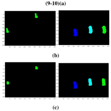
Clearly, a high detection rate and a low false detection rate are desirable. Figure 7, shows the results obtained of the selected 10 images. The masked outputs of the inputs are shown for clarity, rather than the original images, with their marked forged areas. The images also include post-processed images, on which blurring, color reduction, contrast adjustment, brightness changes have been done.
(1-2)(a)
(b)
(c)
(3-4)(a)
(b)
(c)
(5-6)(a)
(b)
(c)
(7-8)(a)
(b)
(9-10)(a)
(b)
(c)
Figure 7. (a) Original image (b) Proposed algorithm (c) Reference algorithm
2(a) refers to the blurred image of 1(a). 3(a) is an image which has color reduction applied to, after forgery. 6(a) is an altered image with brightness change as the post-processing technique. 9(a) refers to an image that has undergone contrast adjustments, post forgery. 3(a), 7(a) and 10(a) are images that consist of multiple copy-move forged regions within the same image. For example, in image 10(a), the leftmost (dark blue in color) and the rightmost (green in color) forged regions are both copied from the middle region (cyan in color). The cyan color is due to the mixture of green + dark blue colors (since copy-move forged regions are colored using the same color). The rest of the images are pure-forged images over original images.
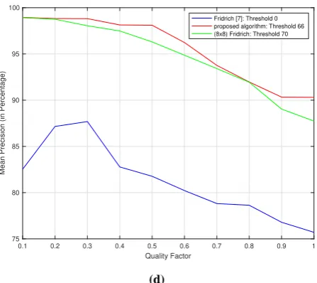
The results are visualized using graphs in Figure 8, where (a) and (b) have been calculated at different values of threshold and quality factor Q, keeping in mind that the best results of the algorithm, with the probability of human error being as much as (+/-) 1, for a particular image, is achieved at that respective combination of the two values. The proposed algorithm has relatively proved to produce better results in all of the cases. Figure 8 (a) and figure 8 (b) give a succinct idea about the accuracy of the proposed algorithm through visual representations of the measuring parameters, f and d. The red graph refers to the proposed algorithm, whereas the blue graph refers to the reference algorithm [7]. Best to the researched knowledge, the false detection rate for each algorithm shown in the graph, is best minimized, beyond which the accuracy of the algorithm would be reduced drastically. Therefore, a balance of accuracy and false detection has been tried to be achieved and the best results were recorded. For a fixed quality factor or fixed threshold value, the proposed algorithm would provide better results than the other two algorithms. This is demonstrated by running the proposed algorithm against the reference algorithm for 20 images. 8x8 blocks are also included in this calculation to prove that the proposed algorithm outperforms both. In 8(c), the quality factor is fixed at the mean, i.e. 0.5, and the mean precision of the 20 images is calculated by varying the threshold values from 0-100. The best threshold values, 66 for proposed algorithm, 70 for 8x8 algorithm and 0 for reference algorithm are then recorded. Figure 8(c), runs the three algorithms at the recorded best threshold values, with varying quality factor from 0.1-1, and plots the mean precision. It is clearly evident that the precision of the proposed algorithm, with varying quality factor and varying threshold values, is better than the reference algorithm [7],
and also when blocks of size 8x8 are used. For 8(c) and 8(d), the red graph refers to the proposed algorithm, the blue graph refers to the reference algorithm [7], and the green graph refers to 8x8 blocks used in the reference algorithm [7].
(a)
(b)
[image:7.595.77.256.72.252.2](d)
Figure 8. (a) Detection rate, d (b) False detection rate, f (c) Mean precision with varying threshold (0-100) (d) Mean
precision with varying quality factor (0.1-1)
5.
CONCLUSION
In this paper, an extension to the existing passive technique of DCT block based copy-move forgery detection method has been presented. The algorithm takes into account the forgeries capable of being detected by sliding 8x8 blocks as well as sliding 16x16 blocks. It was earlier shown in researches that the blocks of size 8x8 rendered a large number of false matches due to which blocks of size 16x16 came up as a better alternative. But due to increment in the size of the blocks, minute segments which were a part of the copy-moved area, not visible to the naked eye, chipped off from the detected region. Moreover, copy-move forgeries in extremely flat areas were hard to detect using the bigger sized blocks. The proposed method took care of both these pitfalls and managed to give better results. The pre-computation of the DCT matrix prior to transformation also keeps a check on the run-time complexity, the average being around 20 seconds. Therefore, it is intended to bring this algorithm into light as an improvement to the previously stated algorithm. The future work will include working upon rotation and scaling invariant features in order to improve the shortcomings of this proposed method.
6.
REFERENCES
[1] Kashyap et al. “An Evaluation Of Digital Image Forgery
Detection Approcahes” in Press:
https://arxiv.org/abs/1703.09968, 30th March 2017. [2] J. Wang, G. Liu, et al, “Fast and robust Forensics for
image region-duplication forgery,” Acta Automatica Sinica, Vol. 35, no. 12, pp. 1488-95, Dec. 2009.
[3] Alkawaz, M.H., Sulong, G., Saba, T. et al. Neural
Comput. & Applic. (2018) 30: 183.
https://doi.org/10.1007/s00521-016-2663-3
[4] Wang H., et al. (2016) An Efficient Passive Auth. Scheme for Copy-Move Forgery Based on DCT. In: Sun X., Liu A., Chao HC. Bertino E. (eds) Cloud Comp. & Security. ICCCS 2016. Lecture Notes in Computer Science, vol 10040. Springer, Cham.
[5] Mishra, A. et al.: A novel image-watermarking scheme using extreme learning machine. In: The 2012 International Joint Conference on Neural Networks (IJCNN), pp. 1–6 (2012).
[6] Tong, X. et al.: novel chaos-based fragile watermarking
for image tampering detection and self-recovery signal process. Image Commun.28, 301–308 (2013).
[7] Fridrich, J., Soukal D., Lukas J.: Detection of copy-move forgery in digital images. In: Digital Forensic Research workshop, Cleveland, pp. 19–23 (2003).
[8] Zhou, L. et al: Blur detection of digital forgery using mathematical morphology. In: Nguyen, N.T., Grzech, A., Howlett, R.J., Jain, L.C. (eds.) KES-AMSTA 2007. LNCS (LNAI), vol. 4496, pp. 990–998. Springer, Heidelberg (2007). doi:10.1007/978-3-540-72830-6 105 [9] Gaharwar et al: “Comprehensive Study of diff. types of
Image Forgeries”, IJSTM, Vol. No. 04, Issue 01,August 2015 ISSN 2394-1537.
[10]Ashima Gupta et al.: “Detecting Copy-Move Forgery using DCT”, IJSRP, Volume 3, Issue 5, May 2013 1 ISSN 2250-3153.
[11]N. D. Wandji et al., “Detection of copy-move forgery in digital images based on DCT,” Journal of Computer Science, vol. 10, pp. 295–302, 2013.
[12]J. Zhao and J. Guo, “Passive forensics for copy-move image forgery using a method based on DCT and SVD,” Forensic Science International, vol. 233, no. 1–3, pp. 158–166, 2013.
[13]Popescu and H. Farid, “Exposing Digital Forgeries by Detecting Duplicated Image Regions,” Tech. Report, TR2004-515, Dartmouth College, Comp. Science, 2004.
[14]W. Luo, et al., Robust detection of region-duplication forgery in digital images, in: International Conference on Pattern Recognition Vol. 04, 2006, 746-749.
[15]Pameli Mukherjee et al, “A Review on Copy-Move Forgery Detection Techniques Based on DCT and DWT”, IJCSMC, Vol.4 Issue.3, March- 2015.
[16]Mukherjee S., Kumar S., and Desai J.,“A Fast DCT based Method for Copy-Move Forgery Detection”, in Proceedings of IEEE 2nd International Conference On Image Information Processing, pp 649-654, 2013.
[17]G. Li, et al., “A Sorted Neighborhood Approach for Detecting Duplicated Regions in Image Forgeries Based on DWT and SVD,” Proc. International Conference on Multimedia and Expo, pp. 1750-1753,2007.
[18]X. Kang, and S. Wei, “Identifying tampered regions using singular value decomposition in digital image forensics,” International Conference on Computer Science and Software Engineering, 2008, Vol. 3, pp. 926-930.
[19]Z. Lin et al., “Fast, automatic and fine-grained tampered JPEG image detection via DCT coefficient analysis,” Pattern Recogn.,Vol. 42, pp. 2492-2250, 2009.
[20]Yao, Heng and Qiao, Tong and Tang, et al.: “Detecting Copy-Move Forgery Using Nonnegative Matrix Factorization”, Proceedings - 3rd International Conference on Multimedia Information Networking and Security, MINES 2011. 10.1109/MINES.2011.104.
[21]B. Xu, G. Liu and Y. Dai, “A Fast Image Copy-Move Forgery Detection Method Using Phase Correlation,” 4th International Conference on Multimedia Information Networking and Security, Nanjing, 2012, pp. 319-322. [22]Yu, J., Han, Q.L.: Detection of copy-move forgery in
[image:8.595.56.280.69.268.2]detecting copy-move forgery,” in Proceeding of the IEEE International Conf. on Acoustics, Speech, & Signal Processing (ICASSP‟09), pp.1053–1056, Taipei, Taiwan. [24]B.Mahdian and S. Saic, “Detection of copy-move forgery using a method based on blur moment invariants,” Forensic Science International, vol. 171, no. 2-3, pp. 180–189, 2007.
[25]Muthukumarasamy, Sridevi. (2012). Copy - Move Image Forgery Detection in a Parallel Environment. Computer Science & Information Technology. 2. 19-29. 10.5121/csit.2012.2303.
[26]Alahmadi, et al. (2016). Passive detection of image forgery using DCT and local binary pattern. Signal, Image and Video Proc. 11. 10.1007/s11760-016-0899-0.
[27]H. Huang, W. Guo, and Y. Zhang, “Detection of copy-move forgery in digital images using SIFT algorithm,” Pacific-Asia Workshop on Computational Intelligence and Industrial Application, Vol. 2, pp. 272-6, Dec. 2008. [28]X. Pan, S. Lyu, Region duplication detection using image
feature matching, IEEE Trans. Inf. Forensics Secur. 5 (4) (2010) 857–867.
[29]Amerini et al., A SIFT-Based Forensic Method for copy-move attack detection and transformation recovery, IEEE Trans. Inf. Forensics Secur. 6 (3) (2011) 1099–1110. [30]M. F. Hashmi et al., “Copy move forgery detection using