Comparative Study of Control Methods’s Application for
Pneumatic System in Simulation Environment
E. Ntimeri
Piraeus University of Applied Sciences, Dept. of Automation
Engineering
Christos Drosos,
PhDPiraeus University of Applied Science, Dept. of Automation
Engineering
D. Tseles
Professor Deputy President P. Ralli & Thivon 250 12244 Aegaleo, Athens
ABSTRACT
In light of the rapid rates of technology development in our times, there has been a continuous effort to introduce everyday technological advances in order to cover better and easier human needs. Especially in the sector of research and applications, the need for simulation programs was seen as offering security to errors, reduce costs and they are accessible to use by professionals and higher education students. This thesis will present the study of control methods’s application for pneumatic system in simulation environment. In addition, it will analyze and describe the operation of the pneumatic system and all the testing methods used in it. The object of the study, which comes with MSc, since it deals with modern automation technology applications, will try to cover questions such as whether these control methods are appropriate and effective for the pneumatic system which is studied, and especially how effective it is the use of a Lookup table to Implement Fuzzy Controller (Fuzzy) with Proportional-Integral-Derivative Controller (PID). For the use of this Lookup table in the pneumatic system of the present study, results have not been extracted to date. These two events are the main purpose of this thesis, in an attempt to perform control of the system on the applications above. The main part of the study will explain the design of the system as well as the type of controllers and the Lookup table. The way of connecting and operating among the pneumatic system, the control methods and the Lookup table, in the simulation environment will be presented in detail, while all this will emerge the conclusions of use specific control methods, the advantages and disadvantages will be discussed and both will be proposed optimizations to further expanding benefits of their operation. As a possible result of using these methods will occur to achieve the optimal and efficient control of the system.
General
Terms
SimulationKeywords
Pneumatic System, Control Methods, Simulink, PID Controller, Lookup Table FuzzyPID Controller
1. INTRODUCTION
Based on the rapid growth of technology, a perpetual effort has been made to bring technological breakthroughs into everyday life so that human needs are met in the best possible way. More specifically, in the field of industry, research and applications, the need for simulation programs was observed, because they are safe for potential errors, minimize costs and are fairly affordable in terms of both professionals and higher education students. This paper will present the study of the application of pneumatic control methods in a simulation environment. In addition, the function of the mental system being studied, as well as all the control methods used in it,
will be analyzed and described. The subject of the study will attempt to answer questions such as whether the specific control methods are appropriate and effective for the particular mental system, and most importantly how efficient is the use of a Fuzzy Matching Proportional -Integral-Derivative Controller (PID).
1.1 Controllers
Proportional Controller (P)A Proportional (P) Controller (Proportional Control) gives the signal output corresponding to the error received at the input. In essence, it is a gain amplification device with KR gain. A Proportional Controller increases the response rate of the system, but it is likely to create a permanent state error depending on the system type, and for zero error it will also have zero output. [15]
Integral Controller (I)
Integral Controller I (Integral Control) gives the output a signal Proportional out to the integrity of the error it receives at the input. Also contains Ki parameter, which has a unit of measurement of 1 sec and is called an integration factor. Each system using the integral controller I, from one system has been converted to another system where the value of the integration coefficient is similar to a physical frequency of the system. As the integration coefficient increases, the physical frequency of the system increases resulting in a faster response of the system and a decrease in the depreciation factor. [15]
Derivative Controller (D)
Derivative Control D (Derivative Control) when at the input of the error signal is in the form of step excitation, the output of the controller is the impulse function with a theoretically infinite width for t = 0. If the error is stable then the output of the Derivative controller is zero. The Derivative Controller limits the error to the permanent state at the stage of the transient response of the systems, but in practice it is never used by itself. [15]
Proportional - Integral Controller (PI)
The Proportional-Integral (PI Controller)sums up the proportional and total control. The use of the integration term is intended to eliminate the error in the permanent state and change the DC gain of the system. The Proportional use term improves the stability of the system and increases the response rate. [15]
Proportional - Derivative Controller (PD)
term D, results increased system damping, allowing for an increase in the proportional gain, thus improving the permanent state error and increasing the system response rate. In practice, the Proportional - Derivative Controller due to derivative D causes amplification of the noise that may occur in the system response, so it is likely to cause problems in cases where there are abrupt changes in the reference signal because the Derivative D to produce output in impact form. [15]
Proportional – Integral- Derivative Controller (PID)
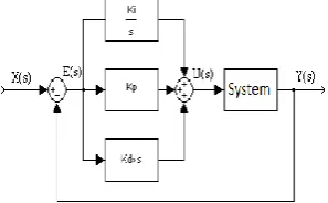
[image:2.595.95.244.271.363.2]The popularity of the Proportional-Integral-Derivative Controller is primarily due to its very good behaviour in contrast to a wide range of operating conditions and secondly its relative simplicity which offers easy and reliable handling. Proportional -Integral- Derivative control combines the effect of the three basic control conditions. The PID control connection is shown in the figure below. [15]
Fig 1: Block Diagram of Proportional -Integral- Derivative Controller
Several industrial-type processes are controlled by the use of PID controllers. The PID proportional-integral Derivative controller has the best overall performance because the system displays a fast response, zero overhead and zero permanent error. To implement such a controller, an appropriate selection of the three parameters of proportional gain, total factor, and Derivative factor should be designed so that the closed loop system has the advantages of all of the controllers associated with the PID controller. In fact, the more difficult to design the particular controller is to give the appropriate values to Kp, Kd and Ki so that one does not adversely affect the other's function. [15]
1.2 Fuzzy Logic
Fuzzy logic is primarily used in machine control. The term "Fuzzy" is given to capture the notion that cannot be attributed to the expressions of truth or lie or even the expression of a lie in part. However, there are alternative suggestions such as Genetic Algorithms and Neural Networks that can perform and function as well as Fuzzy Logic. Also, Fuzzy logic has the advantage of solving problems that cost a lot to humans. With man's experience of Fuzzy logic, he is able to design and build controllers to help him more easily deal with mechanisms he already owns or even create new ones.
Fuzzy logic is used in many computer programs, in satellite systems, in three-phase motors, and in many other applications. Fuzzy logic is an extension of the classical logic of aristocracy. A suggestion may be true "to a certain degree of truth," and not just true or false, that is, the vague logic says things are often not "white-black" but "shades of gray". This idea revolutionized logic theory as it escaped from the 2500-year model, the "0-1" model, "true-false." The way science works require proposals that are either true or false. However, the mode of human logic does not set limits between truth and
false accuracy. The first to deal with Fuzzy logic is Lotfi A. Zadeh in 1965. [8]
1.3 Fuzzy Controllers
Fuzzy controllers are discrete time systems and are characterized by intense non-linearity. Instead, the controllers used in most cases of automated control are usually discrete or continuous and are mainly linear. In both cases the inputs are the error of the output of the controlled system with the reference input and the characteristics of this error, such as the change and the rate of change. The output of Fuzzy and linear controllers may be the control signal or the increment of this signal, depending on the form of the controller. [8]
The main disadvantage of Fuzzy controllers is the large number of parameters that need to be adjusted to meet the criteria set in each case for the desired response of the audited system. Finding the field of Fuzzy variables, the form of the participation functions of the Fuzzy sets, the choice of the deduction mechanism and the operators used by the Fuzzy logic, the design of the Fuzzy rule base, the determination of the possible scaling gains the controller can have, the choice of sampling time and a number of other parameters make the process of tuning the Fuzzy Controller a time-consuming and difficult process. [8]
Additionally, the lack of a complete theoretical and mathematical background for the proper adjustment of these parameters makes the vague control a process that is primarily based on testing and error attempts. The above-mentioned observations have high criticism of the use of Fuzzy logic over system control in relation to the simplicity of linear control. Linear control requires a maximum of three profits, and there are several mathematical tools available that are able to provide a complete theoretical approach to the problem. [8]
The non-linearity of Fuzzy controllers raises concerns about the stability of Fuzzy control systems in practical applications. However, some steps have been taken to address the FLC's stability problem using non-linear systems theory. From the techniques developed a few relate to the use of Lyapynov's direct method to determine conditions for the general stability of systems under ambiguous control, the existence of conditions for the absolute stability of Fuzzy control systems or the application of the Popov criterion for Fuzzy control of continuous systems time and disc criterion for discrete system control. However, most of these techniques are based on conditions and assumptions that are difficult to meet in the real world. Therefore, the stability of Fuzzy controllers is an open problem. [8]
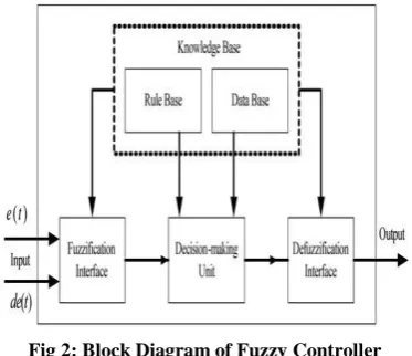
The main building blocks of a Fuzzy Controller are:
The knowledge base where the if-then rules are stored to control the process.
Fuzzy sets are used to represent the input and output variables with verbal terms.
The fuzzifier converts the actual input values into Fuzzy sets
The inference engine processes the Fuzzy outputs and uses the knowledge base to extract the Fuzzy sets of conclusions.
Fig 2: Block Diagram of Fuzzy Controller
In a Fuzzy Controller the inputs are signals and the designer of a Fuzzy Controller has to do the following steps:
1. Verbal distribution of inputs: The designer must represent the input and output variables with the terms.
2. Formulation of rules: After allocating inputs and outputs, vague sets are stored in the form of computer participation functions, followed by the wording of the rules.
3. Definition of the type of Fuzzy implication: Following the formulation of the rules follows the definition of the Fuzzy type of implication. The most common types of Fuzzy implications are:
a) of Mamdani, which uses the max-min operator, which receives the smallest of the participation rates of the undefined values and produces the degree of fulfillment of each rule. The degree of fulfillment of the rule expresses the gravity of the effect of the rule.
b) of Larsen, which uses the max-product operator, which multiplies the participation rates of the undefined values and calculates the degree of fulfillment of the rule. [8]
4. De-imprecision: De-imprecision produce a strict or crisp value from a Fuzzy set. It is the opposite process of deciphering. De-phasing methods are: Centroid defuzzycation or center of area or COA,
the center of weight distribution of the Fuzzy set of output is calculated:
Average Mean of Maxima (MOM) is calculated by averaging the highest exit prices:
Smallest of maxima or SOM is calculated from the highest exit values that have the lowest degree of participation.
Higher than maximum (Largest of maxima or LOM) de-falsification, it is calculated from the highest exit values that have the highest degree of participation. [8]
The method commonly used is Centroid or COA deinter leaving because of its ability to display the smallest error in relation to the other methods. Zadeh, with his book "Fuzzy Sets" in 1965, presented the theory of Fuzzy set theory, with which a price can belong simultaneously to many subsets,
each with a degree of participation. Such a subset is the Fuzzy set, which includes elements, each of which has a degree of involvement. [8]
1.4 Fuzzy Rules
An if-then rule is in its simplest form:
"If x is A then y is B"
where the section "If x is A" is the premise part and the section "then y is B" is the decision-making or consequent part.
Fuzzy rules are hypothetical proposals and are the main building blocks of conclusions. For the sake of understanding it is sufficient to interpret the elements of the above rule:
A, B are the fuzzy sets that come together,
x is the value of an input variable which takes a degree of participation in the fuzzy set A (fuzzyfication process)
y is the output of the system which is derived from an inference engine in an Fuzzy form and states the decision of the rule.
The vague conclusion is then de-falsified by the defuzzification mechanism so that a clear figure is finally obtained.
In the case of more than one input x1, x2, x3, ...xn the rules are as follows:
If x1 is A1 and x2 is A2 and ....xn is An then y is B
Then there may be more than one output. [8]
1.5 Fuzzy Logic Systems
Fuzzy Logic Systems vary according to the forms a rule can take. The most famous of these forms are:
Mamdani press: is the form mentioned above, ie "If x is A then y is B", and was named in honor of Ebrahim Mamdani, who was one of the first to apply Fuzzy Logic. Exits of rules of this form are vague sets.
Sugeno - Takagi type: is a rule of the form "If x is A then y is c", where c is a number or a crisp fuzzy set. Takagi - Sugeno - Kang or T-S-K type: is an extension of the previous rule and is one of the main types of fuzzy rule used in many Fuzzy systems. It has the form "If x is A then y is c0 + c1 x", where c0, c1 Є R. The outputs of rules of this form are functions of the inputs. [8]
2.1 Simulation applications
Simulation as a technique to represent the behavior of a system by another system has a high place in educational applications. Simulation is defined as a method of studying a system with the help of another system. Simulation is a representation that is designed to mimic and allow understanding of the operation of a system. The simulation system results in familiarity with the features and understanding of the functions of the system it represents.
simulation system is to study and experiment with various kinds of systems (to which access is mostly not possible). Users handle the components of the system in a completely interactive way, such as simulating the handling of a warship.
The need for simulation first appeared in the field of scientific research as a technique of studying the effects of an action on a phenomenon without requiring intervention in the phenomenon itself. Simulations are used to explore and understand principles of operation of many technological, physical and social processes. [1]
Types of simulations:
Those who simulate something
a) physical simulation, in which a natural phenomenon is represented by the computing system allowing the user to understand information about it when handling some variables
b) iterative simulation, in which the user executes the program sequentially and selects different values for each parameter
Those who show how to do something:
c) procedural simulation, which aims to teach a sequence of procedures to achieve a goal
d) simulation of a situation in which the user explores alternative paths in a system in order to understand their effects. [1]
2.2 Simulation benefits
It is the only approach to solving problems related to the operation of an inaccessible system
Compared to handling the actual system, it has lower costs
Provides greater "sensitivity" to understanding the relationship between problems
It is a safe method in contrast to many of the real experiments
It offers the possibility of repeating the same phenomenon whenever the user wishes
It has the possibility of integrated insight into the system under study from all sides [3]
2.3 Simulation disadvantages
Sometimes it takes a lot of time to grow and cost a lot
In some cases it may not be the most appropriate method of solving the problem being studied It is not in a position to guarantee that it will lead to
the best possible solution to the problem
It is not certain that it reflects with absolute precision the situation under study [1]
2.2 Introduction to Simulink
Simulink is a valuable tool in Matlab that can simulate systems from a wide range of scientific areas. Its use does not necessitate the knowledge of Matlab, this knowledge is an important advantage because it offers the possibility of more efficient use of it. One of the most important advantages of simulink is its simplicity as it provides the user with many
possibilities. [4] In Simulink, systems are drawn as block diagrams. It offers a great variety of elements of block diagrams, for example summing junctions, transfer functions, and many others. It also provides virtual input and output devices such as function generators. Because of the combination with MATLAB, Simulink’s data can be transferedvery easily, between the programs.
The simulink can be activated by typing the simulink command in the Matlab Command Window or by clicking left in the menu in the menu bar on the top left. Once this is done, a window called Simulink Library Browser will open. The libraries for various applications are shown in the left pane. Each library consists of smaller ones and each of them has a number of blocks, which are displayed in the right part of the window. These libraries cover a wide range of applications, but the following analysis will only be found in the Simulink library. [4]
To open a new simulink file or an existing one, the windows shortcuts are used in the menu bar at the top left in the Simulink Library Browser window. To add a block to the new file from the Simulink Library Browser window, it is simply dragged from the window to the file, in the same way as in windows that are moving files from one window to another. To make the transfer another way, right click on the block and the menu that will appear, select 'add to untitled'. Once a block has been placed in the new file, double-clicking on it opens a window with its settings. Each block has different properties that are discussed below. Also, by right clicking on
the block, a menu appears. Selecting Help will show detailed help for this. [4]
[image:4.595.324.534.491.663.2]2.3 Lookup Table Fuzzy PID Controller
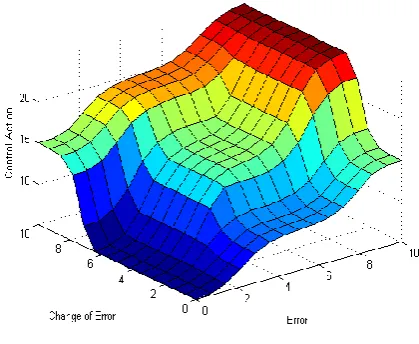
A Fuzzy Inference System (FIS), maps out given inputs to outputs using Fuzzy logic. For example, a standard assignment of a Fuzzy two-input controller can be depicted in a 3-D display. The graph is often referred to, as the control surface graph as shown below. [9]Fig 3: Control Panel Graph
Nonlinear control surfaces can often be accessed with Lookup Tables to simplify the generated code and improve execution speed. For example, a Fuzzy Logic Controller block in Simulink can be replaced by a set of Lookup Tables, a table, for each output defined in the FIS. The Fuzzy Logic Toolbox provides a command like evalfis to calculate the data used in the Lookup Tables.
A non-linear PID controller for a plant in Simulink was designed. The plant is a single entry system with single output at discrete time and the goal is to achieve good benchmarking performance. [9]
[image:5.595.318.509.118.223.2]The Fuzzy Controller in this case is in the feedback loop and calculates PID-like operations through an inconclusive conclusion. The structure of the loop appears are the following
Fig 4: FuzzyPID Controller Structure
The FuzzyPID controller uses a parallel structure as shown below. It is a combination of FuzzyPI control and FuzzyPD control.
Fig 5: Internal FuzzyPID Controller Internal Structure
The change of measurement - (y (k) -y (k-1)) is used instead of the change of error e (k) -e (k-1). In reference signal, direct activation of the derivative energy. The two gain units, GCE and GCU, are used in the forwarding path from r to u to ensure that the error signal e is used in Proportional use action when the FuzzyPID controller is linear.
The design of a FuzzyPID controller involves defining the Fuzzy conjecture system and determining the four scaling factors: GE, GCE, GCU and GU. [9]
The conventional PID controller is a discrete time PID controller with the Euler numerical integration method used in
[image:5.595.62.270.249.430.2]both integrated and generated energy. The gains of the controller are Kp, Ki and Kd. The controller is implemented in Simulink are the following
Fig 6: Conventional PID Controller
Similar to the FuzzyPID controller, the input signal in the derivative action is -y (k) instead of e (k). The gains of the PID controller can be tuned either manually or using coordinate types. By using the pid tune command from the Control System Toolbox ™, an original PID is created. By configuring the FIS and selecting four scaling factors, a linear FuzzyPID control is obtained that reproduces the exact control performance, as the conventional PID controller does. [9]
The construction of the Fuzzy conclusion deduction system is the following
FIS=newfis('FIS','FISType','mamdani','AndMethod','prod','Or Method','probor',...
'ImplicationMethod','prod','AggregationMethod','sum');
Set input E:
FIS = addvar(FIS,'input','E',[-10 10]);
FIS = addmf(FIS,'input',1,'Negative','trimf',[-20 -10 0]); FIS = addmf(FIS,'input',1,'Zero','trimf',[-10 0 10]); FIS = addmf(FIS,'input',1,'Positive','trimf',[0 10 20]);
Set input CE:
FIS = addvar(FIS,'input','CE',[-10 10]);
FIS = addmf(FIS,'input',2,'Negative','trimf',[-20 -10 0]); FIS = addmf(FIS,'input',2,'Zero','trimf',[-10 0 10]); FIS = addmf(FIS,'input',2,'Positive','trimf',[0 10 20]);
Set output u:
FIS = addvar(FIS,'output','u',[-20 20]);
FIS = addmf(FIS,'output',1,'LargeNegative','trimf',[20 20 -20]);
FIS = addmf(FIS,'output',1,'SmallNegative','trimf',[10 10 -10]);
FIS = addmf(FIS,'output',1,'Zero','trimf',[0 0 0]);
FIS = addmf(FIS,'output',1,'SmallPositive','trimf',[10 10 10]); FIS = addmf(FIS,'output',1,'LargePositive','trimf',[20 20 20]);
Set rules:
1. IF E is Negative AND CE is Negative THEN u is-20
2. IF E is Negative AND CE is Zero THEN u is -10
3. IF E is Negative AND CE is Positive THEN u is 0
4. IF E is Zero AND CE is Negative THEN u is -10
5. IF E is Zero AND CE is Zero THEN u is 0
7. IF E is Positive AND CE is Negative THEN u is 0
8. IF E is Positive AND CE is Zero THEN u is 10
9. IF E is Positive AND CE is Positive THEN u is 20
ruleList = [1 1 1 1 1;... % Rule 1
1 2 2 1 1;... % Rule 2
1 3 3 1 1;... % Rule 3
2 1 2 1 1;... % Rule 4
2 2 3 1 1;... % Rule 5
2 3 4 1 1;... % Rule 6
3 1 3 1 1;... % Rule 7
3 2 4 1 1;... % Rule 8
3 3 5 1 1]; % Rule 9
FIS = addrule(FIS,ruleList); [9]
Then the GE, GCE, GCU and GU coefficients are determined from the Kp, Ki, Kd gains used by the conventional PID controller. By comparing the expressions of the traditional PID and the linear FuzzyPID, the variables are related are the following
Kp = GCU * GCE + GU * GE
Ki = GCU * GE
Kd = GU * GCE
The maximum reference step is 1, with the maximum error e being 1. Given that the input area of E is [-10 10], first determine the GE at 10. GCE, GCU and GCU are then solved by the above equations [9]
GE = 10;
GCE=GE*(Kp-sqrt(Kp^24*Ki*Kd))/2/Ki;
GCU = Ki/GE;
GU = Kd/GCE;
To implement the system, the Fuzzy Controller has two inputs (E and CE) and one output (u) that can be replaced by a 2-D lookup table. The lookup table 2-D for FIS is created by creating a loop through the input cluster and calculating the output with the evalfis command. [9]
Step = 10; E = -10:Step:10; CE = -10:Step:10; N = length(E);
LookUpTableData = zeros(N); fori=1:N
for j=1:N
LookUpTableData(i,j) = evalfis([E(i) CE(j)],FIS); end
[image:6.595.54.284.73.240.2]end
Fig 7: The FuzzyPID controller that uses the 2-D Lookup Table
When the control surface is linear as already designed above, the FuzzyPID controller using the 2-D lookup table must produce exactly the same result as the block Fuzzylogic controller uses. In the Simulink model, three different subsystems, namely PID, FuzzyPID and FuzzyPID, are used using the Lookup Table to control the same unit. Closed loop responses to a step change appear in the scope and are exactly the same (three response curves overlapping). [9]
2.2 Application of Lookup table for Fuzzy
controller and correlation with PID
controller
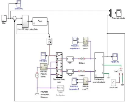
By using the PID, using the Lookup Table, are the following system was implemented.
Fig 8: Pneumatic System with a PID controller using the Lookup Table
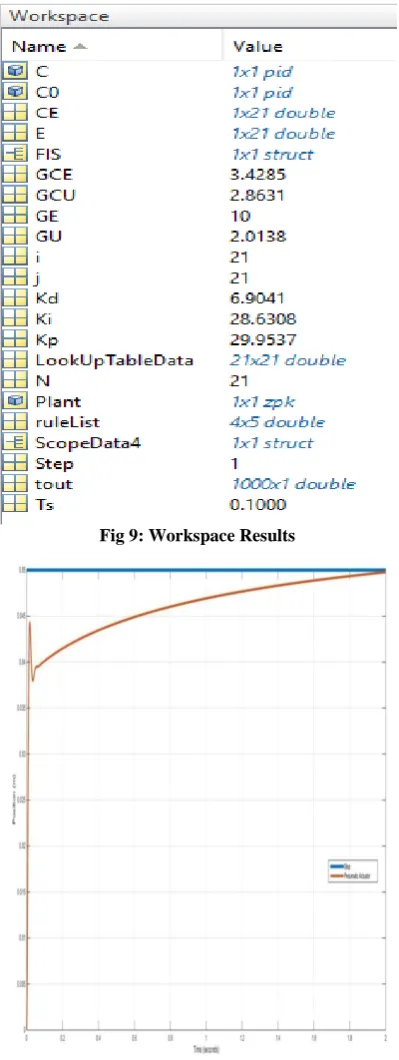
[image:6.595.324.530.79.221.2] [image:6.595.323.532.421.589.2]Fig 9: Workspace Results
Fig 10: Graphical depiction with a PID controller using the Lookup Table
3.1 Comparison of control methods results
Taking the results of the system responses, the following conclusions were drawn as the methods of control of the proportional Controller, proportional -Integral Controller, proportional - Integral - derivative Control and proportional - derivative:By using the proportional Controller (P), the pneumatic system acts quickly and offers the desired effect. However, the proportional Controller is not considered to be ideal for high application requirements as its performance under the influence of the load is not immediately predictable. This has the effect of not being able to deal with possible disorders. [4]
By using the proportional -Integral Controller (PI), the mental system acts quickly and offers the desired effect. However, the integral controller I, which enhances the continuous force acting on the pneumatic piston, causes the system to fail to stabilize and creates oscillations. For this reason, proportional -Integral Controller is not considered appropriate for this experiment. [4], [5], [6], [7]
By using Proportional -Integral- derivative Controller (PID) the mental system acts directly and offers the desired effect. Thanks to the integral I controller, which enhances the continuous force acting on the pneumatic piston, this causes the system to fail to stabilize and creates vibrations.
Although the derivative controller reduces elevation, as a whole the proportional - integral - derivative controller is not ideal for non-linear systems. [4], [5], [6], [7]
By using the Proportional - Derivative Controller (PD), the pneumatic system acts instantly and has high positioning accuracy. It delivers the desired result, without overlaps. Research has shown that Proportional -Derivative Controller offers the best performance in nonlinear systems. [4], [5], [6], [7]
Using the Lookup table to implement the Fuzzy Controller, the desired result was achieved, but the mental system had a more abrupt behavior, and it reached the desired value more slowly than the above control methods.
In summary, it was found that the proportional - derivative Controller (PD) offers the optimal performance in the non-linear system of the particular study, and is considered the most beneficial solution at both practical and mathematical level for the correct position control of the pneumatic piston.
3.2 Future Optimizations
A possible improvement of the system could be achieved by using a Linear Variable Derivative Transformer (LVDT). It is actually a linear displacement measuring sensor. The range of measured displacements depending on the type of LVDT and application ranges from 0.1mm to 1000mm.
Linear variable Derivative transformers are instruments of high precision and have a small error (± 0.5%) because their core is not in contact with the coils, resulting in very low mechanical friction and wear. Despite all their advantages, LVDTs are instruments used to measure small displacements, are quite sensitive and are affected by vibration and temperature. [10]
Fig 11: Linear Variable Derivative Transformer
the secondary are connected in series and with opposite polarity.
[image:8.595.72.263.178.492.2]When the magnetic core is centered, because of the symmetry the voltages induced in the secondary coils are equal and since they are connected to the opposite, the output is zero. Movement of the kernel generates a signal (alternating voltage) at the output whose width is proportional to the displacement and its phase indicates the direction of motion. [11]
Fig 12: Provision of LVDT Sensor
Fig 13: Internal LVDT Sensor Structure
The Linear Variable Derivative Transformer finds many applications in the industry because of the advantages of using it.
More specifically, LVDT is used:
To control the water level in a container. In machining.
In robotics.
In force, pressure and acceleration measurement systems.
To control the position of hydraulic and pneumatic pistons.
To control crane movement [12]
4. ACKNOWLEDGMENT
All authors would like to express their gratitude to the Post-Graduate Program of Studies “Automation of Productions and services” of PUAS, for the financial support to undertake this research project
5. REFERENCES
[1] Educational material for the training of trainers - Chapter 2: Sectors ΠΕ60-70 ΕΑΙΤΥ- Training and Training Sector.
[2] INTRODUCTION TO SIMULINK, Laboratory of Regulation and Informatics, School of Chemical Engineering.
[3] Bachelor Thesis: ELECTRICAL STUDY AND APPLICATIONS, DrososEleftherios, Duntoulakis Maris, T.E.I. Department of Electronics, Department of Automation.
[4] Astrom K., Häglund T., “PID Controllers Theory, Design and Tuning”, Library of Congress Cataloguing-in-Publication Data, 1999.
[5] K.K. Ahn, D.C Thanh, “Nonlinear PID Control to Improve the Control Performance of the Pneumatic Artificial Muscle Manipulator Using Neural Network”, Journal of Mechanical Science and Technology, vol. 19, No1, pp. 106-115, 2005.
[6] Yaolong Tan, “Nonlinear Observer/Controller Design and Its Application to Friction Compensation”, PhD thesis, University Of California, Los Angeles, 2000.
[7] Shen Dongkai Wang Zhanlin, “An adaptive controller based on neural networks for motor-drive load simulator”, IEEE Proceedings of the 35th Conference on Decision Control, Kobe, Japan December 1996.
[8] Bachelor Thesis: Designing a Greenhouse Heating and Ventilation System Using Fuzzy Controller, Spagakos-Liakakos Panagiotis, Sabathianakis Nikolaos.
[9] https://www.mathworks.com/help/fuzzy/examples/using- lookup-table-in-simulink-to-implement-fuzzy-pid-controller.html
[10]http://www.metrolog.net/lvdt.php?lang=en
[11]Bachelor thesis: Sensor Speed Measurement, ZacharioudakisStefanos, Department of Electronics, TEI of Crete, 2010.