Review of Recent Literature on Static Analyses of
Composite Shells: 2000-2010
Mohammad S. Qatu
1, Ebrahim Asadi
1,2, Wenchao Wang
21School of Engineering and Technology, Central Michigan University, Mount Pleasant, USA; 2Department of Mechanical Engineer-ing, Mississippi State University, Starkville, USA.
Email: [email protected]
Received April 19th, 2012; revised May 15th, 2012; accepted May 31st, 2012
ABSTRACT
Laminated composite shells are frequently used in various engineering applications including aerospace, mechanical,
marine, and automotive engineering. This article reviews the recent literature on the static analysis of composite shells.
It follows up with the previous work published by the first author [1-4] and it is a continuation of another recent article
that focused on the dynamics of composite shells [3]. This paper reviews most of the research done in recent years
(2000-2010) on the static and buckling behavior (including postbuckling) of composite shells. This review is con-
ducted with an emphasis on the analysis performed (static, buckling, postbuckling, and others), complicating effects in
both material (e.g. piezoelectric) and structure (e.g. stiffened shells), and the various shell geometries (cylindrical,
conical, spherical and others). Attention is also given to the theory being applied (thin, thick, 3D, nonlinear…). How-
ever, more details regarding the theories have been described in previous work [1,3].
Keywords:
Review; Composite; Static Analysis
1. Introduction
The use of laminated composite shells in many engineer-
ing applications has been expanding rapidly in the past
four decades due to their higher strength and stiffness to
weight ratios when compared to most metallic materials.
Composite shells now constitute a large percentage of
recent aerospace or submarine structures. They are used
increasingly in areas such as automotive engineering,
biomedical engineering and other applications.
Literature on composite shell research can be found in
many national and international conferences and journals.
A recent article [3] focused on the recent research done
on the dynamic behavior of composite shells wherein
problems of free vibration, shock, wave propagation, dy-
namic stability, damping and viscoplastic behavior re-
lated to laminated shells are discussed. Several review
articles on the subject, such as Qatu [2,4], Kapania [5],
Noor and Burton [6,7], Noor
et al
. [8], and Soldatos [9]
covered much of the research done in past decades. Com-
putational aspects of the research were covered by Noor
and Burton [6,7], Noor
et al
. [8,10] and Noor and
Ven-neri [11]. Carrera [12] presented a historical review of
zigzag theories for multilayered plates and shells. He also
reviewed the theories and finite elements for multilayered,
anisotropic, composite plates and shells [13]. Among the
recent books on the subject are those by Reddy [14], Ye
[15], Lee [16], and Shen [17].
Present article reviews only recent research (2000
through 2010) done on the static and buckling analyses
of composite shells. It includes stress, deformation, buck-
ling and post buckling analyses under mechanical, ther-
mal, hygrothermal or electrical loading. Since there are
extensive papers on experimental and optimization stud-
ies in literature, those topics have not been discussed in
this review separately. However, papers in those topics
based on their obtained results are classified in the topics
of this review.
This article classifies research based upon the typically
used shell theories. These include thin (or classical) and
thick shell theories (including shear deformation and
three dimensional theories), shallow and deep theories,
linear and nonlinear theories, and others. Most theories
are classified based on the thickness ratio of the shell
being treated (defined as the ratio of the thickness of the
shell to the shortest of the span lengths and/or radii of
curvature), its shallowness ratio (defined as the ratio of
the shortest span length to one of the radii of curvature)
and the magnitude of deformation (compared mainly to
its thickness). Fundamental equations are listed for the
types of shells used by most researchers in other publica-
tions [1-4].
aspects of research. Focus will first be placed on the vari-
ous shell geometries that are receiving attention in recent
years. Among classical shell geometries are the cylindri-
cal, spherical, conical shells and other shells of revolu-
tion; other shells like shallow shells are also included in
this review. Stress and deformation analyses, in which
various boundary conditions and/or shell geometries are
considered, buckling and post-buckling problems, and
finally research dealing with thermal and/or hygrother-
mal environments will be reviewed. The third aspect of
research will focus on material-related complexities,
which include piezoelectric or other complex materials.
Structural-related complexities will be the final category
that will be addressed. This will include stiffened shells,
shells with cut-outs, shells with imperfections or other
complexities.
2. Shell Theories
Shells are three dimensional bodies bounded by two,
relatively close, curved surfaces. The three dimensional
equations of elasticity are complicated when written in
curvilinear, or shell, coordinates. Researchers simplify
such shell equations by making certain assumptions for
particular applications. Almost all shell theories (thin and
thick, deep and shallow …) reduce the three-dimensional
(3D) elasticity problem into a two dimensional (2D)
problem. The accuracy of thin and thick shell theories is
established when their results are compared to those of
3D theory of elasticity.
2.1. Three Dimensional Elasticity Theory
A shell is a three dimensional body confined by two par-
allel (unless the thickness is varying) surfaces. In general,
the distance between those surfaces is small compared
with other shell parameters. In this section, the equations
from the theory of 3D elasticity in curvilinear coordi-
nates are presented. The literature regarding Mechanics
of laminated shells using 3D elasticity theory will then be
reviewed.
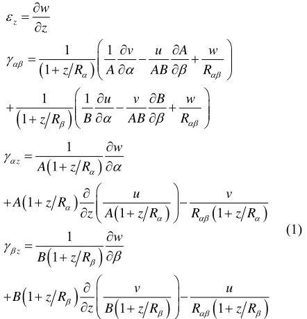
Consider a shell element of thickness h, radii of cur-
vature R
and R
(a radius of twist R
is not shown here)
(
Figure 1
). Assume that the deformation of the shell is
small compared to the shell dimensions. This assumption
allows us to neglect nonlinear terms in the subsequent
derivation. It will also allow us to refer the analysis to the
original configuration of the shell. The strain displace-
ment relations can be written as [1]
1
1
1
1
1
1
u
v
A
w
z R
A
AB
R
v
u
B
w
A
AB
R
[image:2.595.317.531.87.268.2]z R
Figure 1. Stresses in shell coordinates (free outer surfaces).
1 1 1 1 1 1 z w zv u A w
z R A AB R
u v B w
B AB R
z R
1 1 1 1 1 1 1 1 1 1 z z wA z R
u v
A z R
z A z R R z R
w
B z R
v u
B z R
z B z R R z R
(1)
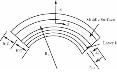
The laminated composite shells are assumed to be
composed of plies of unidirectional long fibers embedded
in a matrix material. On a macroscopic level, each layer
may be regarded as being homogeneous and orthotropic.
However, the fibers of a typical layer may not be parallel
to the coordinates in which the shell equations are ex-
pressed. The stress-strain relationship for a typical nth
lamina in a laminated composite shell made of N laminas
as shown in
Figure
2
is given by Equation (2) [1].
11 12 13 16
12 22 23 26
13 23 33 36
44 45 45 55
16 26 36 66
0 0
0 0
0 0
0 0 0 0
0 0 0 0
0 0
z z
z z
z z
Q Q Q Q
Q Q Q Q
Q Q Q Q
Q Q
Q Q
Q Q Q Q
[image:2.595.321.542.297.526.2]Figure 2. Lamination parameters in shells.
The positive notations of the stresses are shown in
Fig-
ure
1
.
In order to develop a consistent set of equations, the
boundary conditions and the equilibrium equations will
be derived using the principle of virtual work, which
yields the following equilibrium equations
0 0 0 z z z z z z z z A B AB zA A B
B ABq
z
B A AB
z
B B A
A z A B AB z B A
A B ABq
z z
ABq (3)
The principle of virtual work will also yield boundary
terms that are consistent with the other equations. The
boundary terms for
z
= constant are:
0 0 0 0 0 0
0 or
0
0 or
0
0 or
0
z z z z z z
w
u
v
(4)
where
0z,
0zand
0z are surface tractions andu
0,
v
0and
w
0are displacement functions at
z
= constant.
Simi-lar results are obtained for the boundaries
= constant
and
= constant. A three dimensional shell element has
six surfaces. With three equations at each surface, a total
of 18 equations can be obtained for a single-layered
shell.
The above equations are valid for single-layered shells.
To use 3D elasticity theory for multi-layered shells, each
layer must be treated as an individual shell. Both dis-
placements and stresses must be continuous between
each layer (layer
k
to layer
k
+ 1) in a n-ply laminate to
insure that there are no free internal surfaces (
i.e
., de-
lamination) between the layers.
1 1 1 1 1 1, ,
2
, ,
2
, ,
2
, ,
2
, ,
2
, ,
2
, ,
2
, ,
2
, ,
2
, ,
2
, ,
2
, ,
2
k k i k k i
k k i k k i
k k i k k i
z k k i z k k i
z k k i z k k i
z k k i z k k i
u
z
h
u
z
h
v
z
h
v
z
h
w
z
h
w
z
h
z
h
z
h
z
h
z
h
z
h
z
h
(5)
For
k
= 1,···, N – 1.
Among the recent work that used 3D theory of elastic-
ity is the work of Sheng and Ye [18] who presented a 3D
state space finite element solution for composite cylin-
drical shells. Wu and Lo [19] discussed 3D elasticity
solutions of laminated annular spherical shells. Wang
and Zhong [20] used 3D theory to solve problems with
smart laminated anisotropic circular cylindrical shells
with imperfect bonding. Li and Shen [21] studied post-
buckling of 3D textile composite cylindrical shells under
axial compression in thermal environments. Santos
et al
.
[22,23] showed a finite element model for the analysis of
3D axisymmetric laminated shells with piezoelectric sen-
sors and actuators. Sprenger
et al
. [24] investigated
de-lamination growth in laminated structures with 3D-shell
elements and a viscoplastic softening model. Li and Shen
[25,26] analyzed postbuckling of 3D braided composite
cylindrical shells under various loading in thermal
envi-ronments. Alibeigloo and Nouri [27] found a
three-di-mensional solution for static analysis of functionally
graded (FG) cylindrical shells with bonded piezoelectric
layers by utilizing differential quadrature method (DQM)
to the edge boundary conditions and in-plane different-
ials and using state-space approach for discrete points.
Fagiano
et al
. [28] used 3-D finite element method to
accurately predict interlaminar stresses for multilayer
composite shells. Nosier and Ruhi [29] found an exact
solution for a laminated piezoelectric finite panels under
static electro mechanical loading. They reduced PDEs of
equilibrium equations to a system of ODEs using trigo-
nometric functions for displacements in longitudinal and
circumferential directions, and then they solved the re-
sulted system of ODEs. The similar procedure followed
by Ruhi
et al
. [30] to find the solution of a functionally
graded cylinder under thermoelastic loading.
2.2. Thick Shell Theory
of the shell). The main differentiation between thick shell
and thin shell theories is the inclusion of shear
deforma-tion and rotary inertia effects. Theories that include shear
deformation are referred to as thick shell theories or
shear deformation theories.
0 01
1
1
1
z z z zz
R
z R
z
R
z R
(7)
Thick shell theories are typically based on either a dis-
placement or stress approach. In the former, the midplane
shell displacements are expanded in terms of shell thick-
ness, which can be a first order expansion, referred to as
first order shear deformation theories.
where the midsurface strains are:
0 0 0
0
0 0 0
0
0 0 0
0
0 0 0
0
0 0 0
0
0 0 0
0
1
,
1
1
,
1
1
,
1
z zu
v
A
w
A
AB
R
v
u
B
w
B
AB
R
v
u
A
w
A
AB
R
u
v
B
w
B
AB
R
w
u
v
A
R
R
w
v
u
B
R
R
(8a)
The 3D elasticity theory is reduced to a 2D theory us-
ing the assumption that the normal strains acting upon
the plane parallel to the middle surface are negligible
compared with other strain components. This assumption
is generally valid except within the vicinity of a highly
concentrated force (St. Venant’s principle). In other words,
no stretching is assumed in the z-direction (
i.e
.,
z= 0).
Assuming that normals to the midsurface strains remain
straight during deformation but not normal, the dis-
placements can be written as [1]
0 0 0, ,
,
,
, ,
,
,
, ,
,
u
z
u
z
v
z
v
z
w
z
w
(6)
and the curvature and twist changes are:
where
u
0,v
0 andw
0 are midsurface displacements of theshell and
and
are midsurface rotations. An alterna-
tive derivation can be made with the assumption
z= 0.
The subscript (0) will refer to the middle surface in sub-
sequent equations. The above equations describe a typi-
cal first-order shear deformation shell theory, and will
constitute the only assumption made in this analysis
when compared with the 3D theory of elasticity. As a
result, strains are written as [1]
0 0 0 01
1
,
1
1
1
,
1
1
1
z
z
z R
z R
z
z R
z
z R
1
,
1
1
,
1
A
A
AB
B
B
AB
A
A
AB
B
B
AB
(8b)
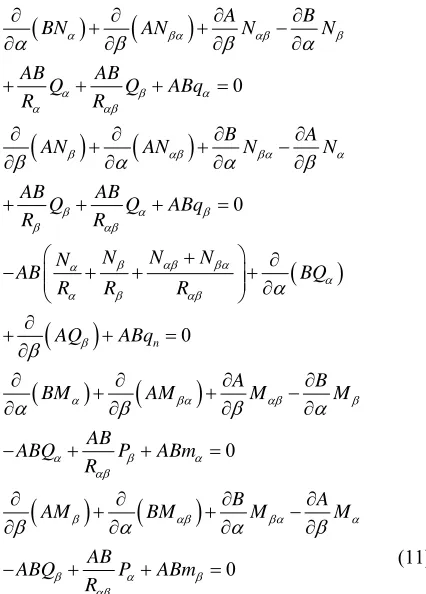
The force and moment resultants (
Figures 3
and
4
) are
obtained by integrating the stresses over the shell thick-
ness considering the (1 +
z R
) term that appears in the
denominator of the stress resultant equations [5]. The
stress resultant equations are:
11 12 16 16 11 12 16 16
12 22 26 26 12 22 26 26
16 26 66 66 16 26 66 66
16 26 66 66 16 26 66 66
11 12 16 16 11 12 16 16
12 22 26 26 12 22 26
ˆ ˆ ˆ ˆ
ˆ ˆ ˆ ˆ
ˆ ˆ ˆ ˆ
A A A A B B B B
N
A A A A B B B B
N
A A A A B B B B
N
N A A A A B B B B
M B B B B D D D D
M B B B B D D D
M M 0 0 0 0 26
16 26 66 66 16 26 66 66
16 ˆ26 66 ˆ66 16 ˆ26 66 ˆ66
D
B B B B D D D D
B B B B D D D D
55 45 55 45 0
45 44 45 44 0
55 45 55 45
45 44 45 44
ˆ
ˆ
ˆ
ˆ
z
z
A
A
B
B
Q
Q
A
A
B
B
R
P
B
B
D
D
R
P
B
B
D
D
(10)
where
A B D A B D A B and D
ij,
ij,
ij,
ij,
ij,
ij,
ˆ ˆ
ij,
ij,
ˆ ,
ijare defined
in [1].
It has been shown [1,5] that the above Equations (9)
and (10) yield more accurate results when compared with
those of plates and those traditionally used for shells [18].
Priciple of virtual work can be used to derive the consis-
tent equilibrium equations and boundary conditions. The
equilibrium equations are [1-4]:
0
0
0
n
A
B
BN
AN
N
N
AB
AB
Q
Q
ABq
R
R
B
A
AN
AN
N
N
AB
AB
Q
Q
ABq
R
R
N
N
N
N
AB
BQ
R
R
R
AQ
ABq
A
B
BM
AM
M
M
AB
ABQ
P
ABm
R
0
0
B
A
AM
BM
M
AB
ABQ
P
ABm
R
M
(11)
The boundary terms for the boundaries with
= con-
stant are
0 0
0 0
0 0
0 0
0
0
0
0
0
0
0
0
0
0
N
N
or u
N
N
or v
Q
Q
or w
M
M
or
M
M
or
(12)
Similar equations can be obtained for
= constant.
Equations (9) and (10) are significantly different from
those that cover most of first order shear deformation
theories (FSDTs) for shells which neglect the effect of
[image:5.595.312.536.98.381.2]z R
in the stress resultant equations. Asadi
et al
. [31]
Figure 3. Force resultants in shell coordinates.
Figure 4. Moment resultants in shell coordinates.
studied static and free vibration of composite shells using
Equations (9) and (10) and compared their results with
other FSDTs and 3D elasticity results. They showed that
presented FSDT improves the prediction of displace-
ments, force resultants and moment resultants signify-
cantly.
[image:5.595.72.285.258.555.2]nomena and demonstrated that this meshless method is
numerically more efficient than the available meshless
fully displacement approaches. Shen [36,37] investigated
postbuckling of shear deformable cross-ply laminated
cylindrical shells under combined loading.
Piskunov
et al
. [38] were interested in a ratational
higher order shear deformation theory of anisotropic
laminated plates and shells. Iozzi and Gaudenzi [39]
studied shear deformable shell elements for adaptive
laminated structures. Han
et al
. [40] performed a geomet-
rically nonlinear analysis of laminated composite thin
shells using a modified first-order shear deformable ele-
ment. Other studies that used a shear deformation shell
theory include those of Li [41], Zenkour [42], Shen [43],
Shen and Li [44], Balah and Al-Ghamedy [45], and
Fer-riera [46].
Zhen and Wanji [47] presented a higher order theory
for multilayered shells and performed analysis on lami-
nated cylindrical shell panels. Khare
et al
. [48] discussed
closed-form thermo-mechanical solutions of higher-order
theories of cross-ply laminated shallow shells. Khare and
Rode [49] showed similar solutions for thick laminated
sandwich shells. Ferreira
et al
. [50] modeled cross-ply
laminated elastic shells by a higher-order theory. Alijani
and Aghdam [51] presented a semi-analytical solution for
stress analysis of moderately thick laminated cylindrical
panels with various boundary conditions. Pinto Correia
et
al
. [52] analyzed laminated conical shell structures for
buckling using higher order models. Matsunaga [53]
studied thermal buckling of cross-ply laminated compos-
ite shallow shells according to a higher order deforma-
tion theory. Oh and Cho [54] investigated a higher order
zigzag theory for smart composite shells under me-
chanical-thermo-electric loading. Yaghoubshahi
et al
. [55]
and Asadi and Faribrz [56] employed general higher-order
shear deformation theory and formulated it to analyze
deep composite shells and plates with mixed boundary
conditions. Benson
et al
. [57] presented a Reissner-
Mindlin shell formulation based on a degenerated solid is
implemented for NURBS-based isogeometric analysis.
They constructed a user-defined element in LS-Dyna for
industrial purposes to analyze elasto-plastic behavior of
shells.
In general, layer-wise laminate theories are used to
properly represent local effects, such as interlaminar
stress distribution, delaminations, etc. These theories are
typically employed for cases involving anisotropic mate-
rials in which transverse shear effects cannot be ignored.
Recent studies include Yuan
et al
. [58] in which a stress
projection, layer-wise-equivalent formulation was used
for accurate predictions of transverse stresses in lami-
nated plates and shells. Kim and Chaudhuri [59,60] and
Chaudhuri and Kim [61] described a layer-wise linear
displacement distribution theory and based their analysis
on it to investigate the buckling and shear behavior of a
long cross-ply cylindrical shell (ring). Leigh and Tafreshi
[62] used layerwise shell finite element based on first
order shear deformation theory to investigate delamina-
tion buckling of composite cylindrical shells. A static
analysis of thick composite circular arches using a layer-
wise differential quadrature technique was performed by
Malekzadeh [63]. Roh
et al
. [64,65] investigated the
thermo-mechanical behavior of shape memory alloys
using a finite element method based on layerwise theory.
The theory of layerwise displacement field was used to
perform a finite element analysis of aero-thermally buck-
led composite shells by Shin
et al
. [66]. The displace-
ment field of a layerwise theory was also used to develop
laminated beam theories by Tahani [67].
2.3. Thin Shell Theory
If the shell thickness is less than 1/20 of the other shell
dimensions (e.g. length) and/or radii of curvature, a thin
shell theory, where shear deformation and rotary inertia
are negligible, is generally acceptable. Depending on
various assumptions made during the derivation of the
strain-displacement relations, stress-strain relations, and
the equilibrium equations, various thin shell theories can
be derived [5]. All these theories were initially derived
for isotropic shells and expanded later for laminated
composite shells by applying the appropriate integration
through laminas, and stress-strain relations. For very thin
shells, the shell is thin such that the ratio of the thickness
compared to any of the shell’s radii or any other shell
parameter,
i.e
., width or length, is negligible when com-
pared to unity. Also, for thin shells, the normals to the
middle surface remain straight and normal when the shell
undergoes deformation. This assumption assures that
certain parameters in the shell equations (including the
z R
term mentioned earlier in the thick shell theory)
can be neglected. The shear deformation can be neglected
in the kinematic equations allowing the in-plane
dis-placement to vary linearly through the shell’s thickness
as given by
0 0
0
z
z
z
, ,
(13)
where the midsurface strains, curvature and twist changes
are
0 0 0
0
0 0 0
0
0 0 0 0 0
0
1
1
1
1
2
u
v
A
w
A
AB
R
v
u
B
w
B
AB
R
v
u
A
u
v
B
w
A
AB
B
AB
R
1
1
,
1
1
A
B
A
AB
B
AB
A
B
A
AB
B
AB
(14b)
normal strains, and
is the in-plane engineering shear
strain. The terms
Q
ijare the elastic stiffness coefficients
for the material. If the shell coordinates (
,
) are parallel
or perpendicular to the fibers, then the terms
Q
16 and
Q
26 are both zero. Stresses over the shell thickness (h)
are integrated to get the force and moment resultants as
given by
and where
0 01
,
1
v
u
w
R
R
A
u
v
w
R
R
A
.
(14c)
11 12 16 11 12 16 0
12 22 26 12 22 26 0
16 26 66 16 26 66 0
11 12 16 11 12 16
12 22 26 12 22 26
16 26 66 16 26 66
N A A A B B B
N A A A B B B
N A A A B B B
M B B B D D D k
M B B B D D D k
M B B B D D D
(16)
Applying Kirchhoff hypothesis of neglecting shear
deformation and the assumption that
zis negligible, the
stress-strain equations for an element of material in the
kth lamina may be written as [1]
11 12 16
12 22 26
16 26 66 k
k
Q Q Q
Q Q Q
Q Q Q
k
(15)
where A
ij, B
ij, and D
ijare the stiffness coefficients aris-
ing from the piecewise integration over the shell thick-
ness (Equation (14b)). For shells which are laminated
symmetrically with respect to their midsurfaces, all the
B
ijterms become zero. Note that the above equations are
the same as those for laminated plates, which are also
valid for thin laminated shells. Using principle of virtual
work yields the following equilibrium equations.
where
and
are normal stress components,
is the
in-plane shear stress component [1],
and
are the
0
0
0
nA B AB AB
BN AN N N Q Q ABq
R R
B A AB AB
AN AN N N Q Q ABq
R R
N N N
N
AB BQ AQ ABq
R R R
where
A BABQ BM AM M M
B A
ABQ AM BM M M
(17)
The following boundary conditions can be obtained for
thin shells for
= constant (similar equations can be ob-
tained for
= constant).
2 1 0 0 0 0 0 0 0 0