Abstract— The control of grid tied solar PV (SPV) system using combination of normalized least mean square (NLMS) algorithm with proportionate normalized least mean square (PNLMS) algorithm is presented in this paper. A PI controller is implemented to regulate the DC link voltage. INC (increment conductance) based maximum power point tracking (MPPT) controller to enhance the maximum power operation of SPV array. The developed system support the three phase AC grid by supplying power and to connected loads with improved power quality. The given inverter control approach takes out the fundamental load current components for reference current generation and to synchronize the SPV system with the grid with very fast response under rapid change scenario. The proposed system includes a SPV array, inverter, filter to take out the ripple and DC components and different types of loads. System provides harmonics in grid currents and voltage within limits as per IEEE-519 and IEEE-1547 standards.
Index Terms— Solar Photovoltaic (SPV) system, inverter, maximum power point (MPPT), increment conductance, normalized least mean square (NLMS) algorithm, proportionate normalized least mean square (PNLMS)
I. INTRODUCTION
PV systems are most widely used renewable energy sources (RES) now a days which possess numerous advantages. These advantages includes locally available generation, high efficiency, less maintenance and minimal environmental impact. Grid integration of SPV power generation systems at the grid side enhance the generation and also create adverse effects such as voltage limit violation, frequency fluctuation, grid instability etc. [1-3]. Grid connected SPV array must follow the codes and regulations of grid defined by the IEEE 1547, IEC 61727 and VDE-AR-N4105. Inverter control in a grid integrated mode of SPV power generation system plays very important role to synchronizing it with grid. Numerous control approaches for grid synchronization and integration of SPV power generation system are widely available in literature [4-7].
Non-linear nature of loads is main source of power quality (PQ) issues which leads too reactive power consumption and distortion of grid currents. All these problems need to be mitigate as causes degradation of power factor and force the M. Rizwan is with Delhi Technological University, Delhi, India. He is working as associate professor in the Department of Electrical Engineering, DTU, Delhi, India. (e-mail: [email protected]).
Priyanka Chaudhary is with Delhi Technological University, Delhi, India. She is working as research scholar in the Department of Electrical Engineering, DTU, Delhi, India. (e-mail: [email protected]).
system to operate with low power factor [8]. Varma et. al. [20] have developed a PV-STATCOM system for enhancing the power transfer capabilities to transmit active power. Hamid et. al. [21] reported an approach to mitigate the current harmonics from a SPV system by placing a power conditioner unit in parallel with the power generation system which operates in feed-forward mode to compensate the output current distortion.
In this paper, combination of NLMS algorithm with PNLMS algorithm is used to control grid tied PV inverter. A PI controller is used to regulate the DC link voltage and maintain it to reference value. INC (increment conductance) based maximum power point tracking (MPPT) controller to enhance the maximum power operation of SPV array. The modelling and simulations of the given system are performed using MATLAB/Simulink platform.
II.SYSTEM DESCRIPTION
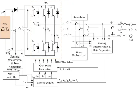
The developed system consists of a 10 kW SPV array, voltage source inverter (VSC), various types of loads such as linear and nonlinear loads, ripple filter, three phase AC grid as shown in Fig.1. Ripple filter which is the combination of R and C used to remove the excessive fluctuations from the inverter output.
A.Solar PV Array
A SPV array combines several PV modules which are again formed by series and parallel interconnection of various PV cells. SPV array is designed as per the power requirement of applications, PV modules are connected in series configuration if high voltage is required and for high current application parallel configuration is used. The output current equation can be written as [8]:
(1)
Where reverse saturation current Irs is:
(2)
The saturation current as a function of temperature can be written as:
(3)
Where, k denotes the Boltzmann constant (1.38 x 10⁻²³ J K-1), q the electronic charge (1.602 x 10⁻¹⁹ C), T cell temperature (K); A diode ideality factor, Rs the series
Hybrid Control Approach using NLMS and
PLMS Algorithms for Grid Connected SPV
System
M. Rizwan, and Priyanka Chaudhary
SPV Array/
Fuel Cell Cdc
Grid Ipv Linear/ Nonlinear Load VSC Lf Lf Lf Isa Isb Isc Iina Iinb Iinc a b c S1 S2 S3 S5 S4 S6 Vsa Vsb Vsc VPV VDC Sensing, Measurement & Data Acquisition MPPT Controller Ipv Ipv VPV Sensing, Measurement & Data Acquisition Ripple Filter Gate Pulse Generation ILa ILb ILc Zs Zs Zs Inverter control Isa*
Isb* Isc*
Vab, Vbc ,ILa,ILb and ILc Isa,Isb and Isc IGBT Gate Pulses
PPV
[image:2.595.77.522.49.335.2]Vdc* VDC
Fig. 1. System description
resistance (Ω) and Rp is the shunt resistance (Ω). NS and Np
are number of cells connected in series and parallel respectively.
B.Inverter Design
Inverter consists of three arms and each arm contains two IGBT with antiparallel diodes and designed for 415 V, 25 kW at 0.8 p.f. lagging load. A combination of series resistance and capacitance is used as ripple filter and design values are given in appendix []. The appropriate design of interfacing inductor for inverter plays very important for tracking the reference current.
III. CONTROL DESIGN
A.Maximum Power Point Tracking
A maximum power point tracking (MPPT) technique is required to extract the maximum power from Solar PV (SPV) array. Various MPPT techniques are presented in the literature [9-10] which includes perturb and observe (P&O), incremental conductance (INC), constant voltage, open circuit voltage, short circuit current, extremum seeking control and techniques based on artificial neural networks, fuzzy logic, genetic algorithms. INC technique has been implemented in present work and works well than other available techniques [11]. This method utilizes the fact that the slope of PV array output curve is always equals to zero at maximum power point (MPP). This curve has positive slope for values less than MPP and negative for which has values more than MPP.
B.Inverter Control
Inverter control plays very important role for design and development of grid integrated solar PV systems. The knowledge of phase angle and frequency of grid side voltage
is necessary to for inverter control. The reference sinusoidal source currents for generating inverter gate pulses obtained by using present control algorithm. The implemented control algorithm combines normalized least mean square (NLMS) algorithm with proportionate normalized least mean square (PNLMS) algorithm and a PI controller to regulate the DC link voltage. This results in a more stability with high convergence rate.
Amplitude of terminal voltage and unit templates:
Measured grid side line voltages at point of common coupling (PCC) is used to find grid phase voltages ( and ) calculated as:
(4)
The terminal voltage amplitude at PCC can be computed as:
The in-phase unit templates of , and are obtained as:
Quadrature unit templates can be obtained from in phase unit templates as following:
(7) Reference grid currents generation:
Voltage at dc link ( ) is measured and compared with
the reference dc link voltage ( ) to calculate the active loss component.
which is further being used to get active current component . The controller’s output at
instant:
(9)
Error (difference between sensed and reference
terminal voltage and respectively) at point of common coupling passed through a PI controller to compute reactive loss component which needed to maintain the constant terminal voltage.
(10)
The controller output at is:
(11)
Where, and are proportional and integral gains
respectively. Fast dynamic response can be achieved with a feed forward weight which is a function of solar power ( )
and .
(12)
Fundamental active and reactive components of load current extraction done by taking load currents ( ).
The error for the system is considered as:
(13)
In above equation n shows the phases a, b and c, depicts
the fundamental active load current component of phase ‘j’.
(14)
Here µ is adaption constant and values lie between 0 and 2. NLMS algorithm contribute as :
(15)
PNLMS algorithm contribute as :
(16)
Where, 0<α<-0.5 and regulation constant 0.001<ε<0.01 for finite output. [12] can be written as:
+γ (17)
Where, δ and γ are considered as positive small constant for finite
Weighted values for fundamental active current components for all phases:
(18)
( ) is calculated as below:
(19)
Similarly, weighted values for mean reactive component of load currents ( ) is obtained as:
(20)
Net fundamental active load current component is given as:
(21)
Net fundamental reactive current component of load current:
(22)
The reference grid currents for active and reactive components are given in equation 23 and 24 respectively:
(23)
(24)
Net reference grid currents ( ) is given as: (25)
Gate pulses for inverter switches are generated by comparing reference ( ) and actual ( )
grid currents.
IV. RESULTS
The performance of developed system has been tested for various cases such as STC conditions, various irradiance levels with different kind of loads such as linear, nonlinear, balanced and unbalanced. Proposed model has been validated through analysis of various parameters such as grid voltage (Vs), DC bus voltage (Vdc), AC grid currents,
(Is), load currents, (IL) the real power from and to the grid
(Pg), the reactive power (Qg), SPV current (Ipv), SPV
voltage (Vpv), SPV power (Ppv), inverter current (Iinv) and
AC terminal voltage (Vt). Fig. 2 shows results of the system
for dynamic linear load scenario.
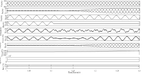
Fig. 3 presents dynamic operation of the system under unbalanced nonlinear loads for zero voltage regulation (ZVR) mode. At 1.1 s phase ‘c’ of load is removed from supply, even under this situation, source currents ( ) maintained sinusoidal. The proposed control helps Vt and
Vdc are maintained at 415 V and 700 V, respectively without
Fig. 2. Performance under linear dynamic load.
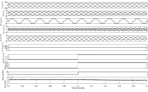
Fig. 4. Performance under variable solar irradiance.
Fig. 5. THD spectrum for load current and grid current.
V.CONCLUSION
The proposed system is developed in MATLAB/Simulink platform. Performance of the proposed control approach is analyzed for linear and nonlinear loads with steady state and dynamic states. Load unbalancing and solar irradiance variation to validate the results of the control algorithm and satisfactory performance has been achieved. System provides fast response and operates unity power factor (UPF) mode gives reactive power compensation, load balancing, maximum power extraction and harmonic
reduction. Grid currents harmonics and voltage fluctuations are within limits as per IEEE-519 and IEEE-1547 standards.
APPENDIX
The developed system design specifications.
AC Grid specifications= 3 ϕ, 415 V, 50 Hz, SPV array voltage (VMPP) = 700V, SPV array current (IMPP) = 13.5A,
SPV array power (PMPP) = 10kW, Interfacing inductor (Lfa=
Lfb= Lfc) = 2.6 mH, DC bus capacitor (CDC) = 10mf, DC bus
voltage (VDC) = 700V, Ripple Filter (Rf) and (Cf) = 5 Ω, 10
REFERENCES
[1] S. J. Steffel, P. R. Caroselli, A. M. Dinkel, J. Q. Liu, R. N. Sackey, and N. R. Vadhar, “Integrating solar generation on the electric distribution grid”, IEEE Trans. Smart Grid, vol. 3 (2), 2012, pp. 878-886.
[2] Y. W. Li, J. He, “Distribution system harmonic compensation methods: an overview of DG-interfacing inverters”, IEEE Trans. Ind. Elect., vol. 8, no. 4, Dec. 2014, pp. 18-31.
[3] P. Chaudhary and M. Rizwan M, “Voltage regulation mitigation techniques in distribution system with high PV penetration: A review”, Renewable and Sustainable Energy Reviews, vol. 82, no. 3, 2018, pp. 3279-3287.
[4] N. Beniwal, I. Hussain and B. Singh, “Implementation of DSTATCOM with i-PNLMS based control algorithm under abnormal grid conditions”’ 7th India International Conference on Power Electronics (IICPE), Patiala 2016, pp. 1-5.
[5] R. K. Agarwal, I. Hussain and B. Singh, “Three-phase single-stage grid tied solar PV ECS using PLL-less fast CTF control technique”, IET Power Electronics, vol. 10, no. 2, 2017, pp. 178-188.
[6] S. Adhikari and Li. Fangxing, “Coordinated V-f and P-Q control of solar photovoltaic generators with MPPT and battery storage in microgrids”, IEEE Transactions on Smart Grid, vol. 5, no. 3, 2014, pp. 1270–1281.
[7] P. Chaudhary and M. Rizwan, “A Predictive Current Control for Solar PV Fed VSI in Distribution System,” 17th IEEE International Conference on Environment and Electrical Engineering (IEEE EEEIC17), June 6-9, 2017, Milan, Italy.
[8] J. A. Gow and C. D. Manning, “Development of a photovoltaic array model for use in power-electronics simulation studies,” IEEE Proceedings on Electric Power Applications, vol. 146, no. 2, 1999, pp. 193–200.
[9] A. R. Reisi, M. H. Moradi and S. Jamsab, “Classification and comparison of maximum power point tracking techniques for photovoltaic system: A review”, Renewable and Sustainable Energy Reviews, vol. 19, 2013, pp. 433-443.
[10] Y. C. Kuo, T. J. Liang and J. F. Chen, “Novel maximum-power point tracking controller for photovoltaic energy conversion system”, IEEE Transaction on Industrial Electronics, vol. 48, no. 3, 2001, pp. 594– 601.
[11] M. Rizwan, P. Chaudhary and T. Ahmad, “Performance Analysis of Maximum Power Point Tracking Techniques for Photovoltaic Systems”, Advanced Science Letters, vol. 20, 2014, pp. 1231-1247. [12] A. Maleki and K. Nayebi, “A new efficient PNLMS based algorithm
for adaptive line echo cancellation”, Seventh International Symposium on Signal Processing and Its Applications, vol. 2, 2003, pp. 555-558.