Ames Laboratory Publications
Ames Laboratory
2015
Magneto-structural transformations via a solid-state
nudged elastic band method: Application to iron
under pressure
Nikolai A. Zarkevich
Ames Laboratory, [email protected]
Duane D. Johnson
Iowa State University, [email protected]
Follow this and additional works at:
http://lib.dr.iastate.edu/ameslab_pubs
Part of the
Condensed Matter Physics Commons
,
Engineering Physics Commons
, and the
Metallurgy Commons
The complete bibliographic information for this item can be found at
http://lib.dr.iastate.edu/
ameslab_pubs/270
. For information on how to cite this item, please visit
http://lib.dr.iastate.edu/
howtocite.html
.
Magneto-structural transformations via a solid-state nudged elastic band
method: Application to iron under pressure
Abstract
We extend the solid-state nudged elastic band method to handle a non-conserved order parameter, in
particular, magnetization, that couples to volume and leads to many observed effects in magnetic systems. We
apply this formalism to the well-studied magneto-volumecollapse during the pressure-induced transformation
in iron—from ferromagnetic body-centered cubic (bcc) austenite to hexagonal close-packed (hcp)
martensite. We find a bcc-hcp equilibrium coexistence pressure of 8.4 GPa, with the transition-state enthalpy
of 156 meV/Fe at this pressure. A discontinuity in magnetization and coherent stress occurs at the transition
state, which has a form of a cusp on the potential-energy surface (yet all the atomic and cell degrees of
freedom are continuous); the calculated pressure jump of 25 GPa is related to the observed 25 GPa spread in
measured coexistence pressures arising from martensitic and coherency stresses in samples. Our results agree
with experiments, but necessarily differ from those arising from drag and restricted parametrization methods
having improperly constrained or uncontrolled degrees of freedom.
Keywords
Materials Science and Engineering, Enthalpy, Iron, Ferromagnetism, Discontinuities, Density functional
theory
Disciplines
Condensed Matter Physics | Engineering Physics | Metallurgy
Comments
The following article appeared in J. Chem. Phys.
143
, 06477 (2015) and may be found at
http://dx.doi.org/
10.1063/1.4927778
.
Rights
Copyright2015 American Institute of Physics. This article may be downloaded for personal use only. Any
other use requires prior permission of the author and the American Institute of Physics.
Magneto-structural transformations via a solid-state nudged elastic band method:
Application to iron under pressure
N. A. Zarkevich and D. D. Johnson
Citation: The Journal of Chemical Physics 143, 064707 (2015); doi: 10.1063/1.4927778 View online: http://dx.doi.org/10.1063/1.4927778
View Table of Contents: http://scitation.aip.org/content/aip/journal/jcp/143/6?ver=pdfcov
Published by the AIP Publishing
Articles you may be interested in
Pressure-magnetic field induced phase transformation in Ni46Mn41In13 Heusler alloy
J. Appl. Phys. 116, 223904 (2014); 10.1063/1.4903958
Pressure effects on the stability of magnetic structure of Mn 3 Zn 1 − x Ge x N ( x = 0 , 0.1 )
J. Appl. Phys. 106, 113905 (2009); 10.1063/1.3257258
Superhigh strains by variant reorientation in the nonmodulated ferromagnetic NiMnGa alloys
Appl. Phys. Lett. 81, 2818 (2002); 10.1063/1.1512948
Change of the magnetic properties of CoSiF 6 ⋅ 6(H 2 O ) at structural transformations under pressure. Determination of the g factor
Low Temp. Phys. 26, 558 (2000); 10.1063/1.1289124
Magnetization and magnetocrystalline anisotropy of R 2 Fe 17 intermetallics under pressure
J. Appl. Phys. 85, 4874 (1999); 10.1063/1.369127
THE JOURNAL OF CHEMICAL PHYSICS143, 064707 (2015)
Magneto-structural transformations via a solid-state nudged elastic band
method: Application to iron under pressure
N. A. Zarkevich1,a)and D. D. Johnson1,2,a)
1The Ames Laboratory, U.S. Department of Energy, Ames, Iowa 50011-3020, USA 2Materials Science and Engineering, Iowa State University, Ames, Iowa 50011-2300, USA
(Received 21 May 2015; accepted 20 July 2015; published online 14 August 2015)
We extend the solid-state nudged elastic band method to handle a non-conserved order parameter, in particular, magnetization, that couples to volume and leads to many observed effects in mag-netic systems. We apply this formalism to the well-studied magneto-volume collapse during the pressure-induced transformation in iron—from ferromagnetic body-centered cubic (bcc) austenite to hexagonal close-packed (hcp) martensite. We find a bcc-hcp equilibrium coexistence pressure of 8.4 GPa, with the transition-state enthalpy of 156 meV/Fe at this pressure. A discontinuity in magnetization and coherent stress occurs at the transition state, which has a form of a cusp on the potential-energy surface (yet all the atomic and cell degrees of freedom are continuous); the calculated pressure jump of 25 GPa is related to the observed 25 GPa spread in measured coexistence pressures arising from martensitic and coherency stresses in samples. Our results agree with experiments, but necessarily differ from those arising from drag and restricted parametrization methods having improperly constrained or uncontrolled degrees of freedom. C 2015 AIP Publishing LLC.[http://dx.doi.org/10.1063/1.4927778]
I. INTRODUCTION
Magneto-structural transformations are quite common in magnetic systems.1Their generic feature is a rapid change of
magnetization and density, referred to as a magneto-volume collapse.2While the nudged elastic band (NEB)3and the solid-state nudged elastic band (SSNEB)4 methods correctly ac-count for all atomic degrees of freedom (DoF), they expect the transition state (TS) region in the form of a saddle. The oft-used drag methods can miss the correct TS (due to a possible discontinuity in some of the DoF), and a restricted parame-trization can overlook it (due to a constrained search space). Here, we generalize the TS search algorithm within the SS-NEB method to make it suitable for the TS of various shapes (not only saddles but also cusps) and apply it to iron under pressure, which displays a magneto-volume collapse of 11% at the TS due to the loss of magnetization,1a non-conserved
order parameter that does not have to be continuous, unlike the atomic or cellular DoF.
Iron is the most stable element produced by nuclear reac-tions, the most abundant element in the Earth core, and is also very common in extraterrestrial meteorites.5Metallic iron is known for its magnetism and technological impact. Deeper understanding of its properties under pressure affects metal-lurgy, materials science and engineering, geophysics, and plan-etary sciences.6
Due to its importance, the iron body-centered cubic (bcc)-hexagonal close-packed (hcp) (α-ε) transition and its mech-anism have long been studied.6–27 In spite of iron’s
struc-tural simplicity under pressure, the minimum-energy pathway (MEP) and the TS remained unresolved, in particular, because
a)Electronic addresses: [email protected] and [email protected]
of the improper handling of magnetic DoF and expectation of saddle point behavior near the TS. We use the bcc-hcp transition in iron as a prototype for the quantitative description of magnetic systems via the SSNEB method4and its
modifica-tions.28For a magneto-structural transformation, we show that
the TS is a cusp on the potential energy surface (PES) and is not a single electronic state, but a duality of a non-magnetic (NM) and magnetic states with the same atomic and cell coordinates, the same enthalpy, but different electronic structure. As a result of the coherency stress between those two electronic states, a pressure discontinuity at the TS exists, which can be related to the experimental scatter in the coexistence pressures of magnetic and non-magnetic phases.
As discussed below, the simplest observed7,29 bcc-hcp transition in iron can be described in a 2-atom cell by one atomic and three cell (4 total) degrees of freedom, with the rest being constant during the whole transformation due to symme-try (Fig.1). Although no symmetry constraints are imposed in our SSNEB calculations, our results confirm that those DoF that are assumed constant remain constant during the whole transformation. Thus, the atomic DoF in a 2-atom cell can be completely described by a continuous shuffles(which changes linearly from 0 for bcc to 1 for hcp), with direct coordinates of atom 1 fixed at(0; 0; 0)and atom 2 at (12[1+3s]; 12[1+s3]; 12). The 3 independent cell DoF for an orthorhombic unit cell are the lengths of the 3 mutually orthogonal vectorsa1+a2,
a2−a1, andcor 3 independent functions of them (e.g., cell
volumeV, shear angleϑ, andc/a). We define diagonal vector
b=a2−a1, which is orthogonal tocand shuffles(directed
along the other diagonal a1+a2), see Fig.1. We emphasize that the complete description of this bcc-hcp transformation requires consideration of all 4 independent atomic and cell DoF.
064707-2 N. A. Zarkevich and D. D. Johnson J. Chem. Phys.143, 064707 (2015)
FIG. 1. Left: Smallest (2-atom) bcc unit cell that permits a bcc→hcp trans-form using a shuffle-shear concept. Right: bcc→hcp via shuffle-shear: bcc ([110] projection) is shown by black atoms and solid lines and hcp ([0001] projection) is shown as blue open circles and dashed lines, with ABAB stacking of corner A and central B atoms. Vectors(red) gives the shuffle direction from bcc to hcp. The shear angleϑchanges from 70◦in bcc to 60◦ in hcp.
Previously, the bcc-hcp transformation path was usu-ally described by oversimplified models.7,8 In particular, the
shuffle-shear model7 that controls only 2 DoF (shuffle and
shear) is a drag method; the other unit cell DoF (volume and
c/adistortion) are left uncontrolled. Drag methods improperly permit discontinuities in some uncontrolled DoF; hence, the resulting pathway can “tunnel” under the TS (due to discon-tinuous DoF) and bypass it, missing or underestimating the true enthalpy barrier.4The rapid-nuclear-motion (RNM)
approxi-mation (which imposes a fixed shear and relaxes the shuffle) leads to an unphysical discontinuity in the (uncontrolled) atomic shuffle, giving a low bcc-hcp barrier in the form of a cusp, with equal enthalpies of the bcc and hcp phases at the calculated pressure of 13.1 GPa.8Fixing both shuffle and shear but relaxing volume (and magnetization)9 permits all atomic DoF to be continuous (more correct), but improperly uncouples continuous atomic DoF and unit cell DoF (volume andc/a), which may be discontinuous. We emphasize that the shuffle-shear model7 is a drag method that controls of only
2 DoF (shuffle and shear), leaving an uncontrolled unit cell volume beyond consideration.9
The iron bcc-hcp transformation path was calculated directly using density functional theory (DFT) for the shuffl e-shear model in a 2-atom cell (Fig.1), with full volume relaxa-tion for each pair of shuffle-shear values,9finding a MEP with
a cusp due to the magneto-volume collapse. In addition to a discontinuity in volume, the reported MEP cusp was rounded due to the use of an approximate symmetry-adapted polyno-mial to analytically determine the entire potential energy sur-face. More recently, possible concerted transformations were investigated (including 3 shuffling mechanisms within the RNM at constant shear and fixed 71.5 bohrs3/atom volume), finding a TS in the form of a cusp,27but missing the observed
magneto-volume collapse—disappearance of magnetization with a concomitant 11% drop in volume.
Classical inter-atomic potentials typically ignore depen-dence on the magnetic state, giving an irrelevant path for magneto-structural transitions. Thus, the embedded atom method (EAM) provided an overestimated transition pressure of 31–33 GPa for the uniform19and 14 GPa for the uniaxial compression.18
While the pressure-induced bcc-hcp transformation in iron has been extensively studied, its complete theoretical description accounting for all relevant DoF is still needed. Recall that the traditional SSNEB method4 can search the entire phase space, but requires a continuous and differentiable
PES with the TS in the form of a saddle (e.g., as in Li30),
which can be addressed by the available codes31 with one32 or (more stable) two28climbing images, while for a magneto-structural transformation, the TS is a cusp on the PES with a discontinuity of atomic forces and stress components, where a climbing image will not stop. We extend the unrestricted SSNEB formalism (theAppendix) and apply it to the bcc-hcp transformation in iron under pressure. We compare our results to experiment and contrast them with the previous theoretical discussions.
II. RESULTS
Using our modified SSNEB method (see theAppendix)
with properly coupled cell and atomic DoF, we perform calcu-lations at several values of the applied hydrostatic pressure
P, including 0, 8.4, 10, and 20 GPa. Because an equilibrium coexistence is rarely observed in experiment, here we provide the barrier versus pressure (Figs.2–4), emphasizing generality of our quantitative description. The result at the equilibrium coexistenceP0=8.4 GPa is given in Fig. 3 in Ref.6(see also
our Fig.5). We emphasize that we do not impose any sym-metry restrictions or constraints on any DoF, and our uncon-strained SSNEB results below show that some of the atomic DoF remain constant.
A. Atomic and cell degrees of freedom
The 2-atom cell has 6 atomic DoF (3 of which are inde-pendent) and 6 cell DoF (3 lengths of the lattice translation
FIG. 2. For 2-atom cell, enthalpyH(meV/atom) relative to bcc Fe, mag-netization M (µB/atom), and volume V (Å3per unit cell) vs. shuffle from SSNEB at 3 hydrostatic pressures:P=0 (black), 10 (red), and 20 GPa (blue). Higher-enthalpy states with intermediate M are shown as filled shapes. Dotted vertical lines and dashes are at discontinuities inM.
[image:5.594.336.516.423.696.2]064707-3 N. A. Zarkevich and D. D. Johnson J. Chem. Phys.143, 064707 (2015)
FIG. 3. Lattice parametersa,b=2asin(ϑ/2), andc(Å) versus shuffle for 3 values of external pressure (GPa):P=0 (black), 10 (red), and 20 (blue). Trajectory of the TS is given by dashed line.
vectors and 3 angles between them). We find that out of the 3 independent atomic DoF, only 1 (shuffle) is interesting, while the other two can be chosen in such a way that they remain constant during the whole transformation. Among the 6 cell DoF, values of 2 out of 3 angles remain constant (90◦). The cell can be chosen with a mirror symmetry, so that 2 lengths of the translation vectors are equal (Fig.1). We are left with 1 changing atomic DoF (shuffle) and 3 cell DoF. The direct coordinates of atoms are (0, 0, 0) and (12[1+s3]; 21[1+3s]; 12), so that the second ones change from (1/2, 1/2, 1/2) in bcc to (2/3, 2/3, 1/2) in hcp (Fig.1).
[image:6.594.77.254.48.232.2]We find that the atomic shufflesis a continuous monotonic function of the SSNEB path variable, hence all the other path-dependent variables can be expressed in terms of the shuffle. All 3 independent cell DoF are plotted in terms of the shuffle
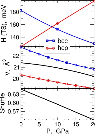
FIG. 4. Versus external pressure P, enthalpy (meV/Fe) of the TS (156 meV/Fe atP0=8.42 GPa) relative to bcc (blue) and hcp (red); unit cell volume of the TS (black), bcc (blue), and hcp (red) structures; and shuffle at the TS.
FIG. 5. For 2-atom cell, SSNEB enthalpyH(meV/atom), magnetizationM
(µB/atom), volumeV (Å3per cell), and internal pressureP(GPa) versus MEP. SSNEB results for variableM(analytic continuation ofHnear cusp) are compared to those at fixedM, i.e.,M=0 (blue short-dashed line) and 2.13µB/Fe (red long-dashed line). Two fixed-M solutions never cross on the PES, so there is a jump between them (vertical brown dashed line, as seen inV vs. path) to avoid higher-enthalpy solutions (blue and red dotted lines). Higher-enthalpy intermediate state (black squares) with intermediate
Marises from improper VASP convergence.
in Fig.3, where we introducedb=2a sin(ϑ/2)as the length of b=a2−a1 (Fig.1). Figures2 and 3 show that although there is a discontinuity in magnetization at the TS, all the atomic and cell DoF are continuous functions versus the MEP (and the shuffle). This is in contrast to drag methods that have unphysical discontinuities in some of the uncontrolled DoF. At P0=8.4 GPa, the TS is characterized bya =2.41 Å, b
=2.59 Å, c=3.99 Å, and s=0.6, with V =21.0 Å3, ϑ=65.1◦, andc/a=1.6594.
Although the SSNEB path depends on the Jacobian J,
coupling atomic and cell degrees of freedom,4 the TS is
invariant for reasonable finite values ofJ(typically between 1 and 5 Å). At anyJ, the SSNEB path goes through the TS and the terminal states. With J≈3 Å, we find an approximately linear dependence between the atomic shufflesand cell trans-lationb(Fig.3). Dependence of the shuffle at the TS on the hydrostatic external pressurePis nearly linear (Fig.4bottom). At the equilibrium coexistence pressure P0=8.42 GPa, where
bcc and hcp phases have equal enthalpies,6 the calculated enthalpy of the TS is 156 meV/atom above the terminal states. We emphasize that this value is the same from the intersec-tion of lines connecting the SSNEB results at 0, 10, and 20 GPa (Fig.4), from our SSNEB calculation atP0(Fig.5), and from
direct DFT calculations of the electronic structure (Fig.6) and enthalpy of the TS atomic configuration atP0(Fig.7).
B. Electronic structure and magnetization
[image:6.594.88.240.491.708.2]064707-4 N. A. Zarkevich and D. D. Johnson J. Chem. Phys.143, 064707 (2015)
FIG. 6. Total spin DOS [(states/atom)/eV] for the bcc-hcp transforma-tion at P0=8.4 GPa. Majority (minority) spin states are plotted on posi-tive (negaposi-tive) axes. Endpoints are (a) non-magnetic hcp and (e) magnetic (M=2.12µB/Fe) bcc. TSs are (b) non-magnetic (M=0) and (d) magnetic (M=2µB/Fe), having same atomic structure and enthalpy (the cusp in Fig. 5). (c) Higher-enthalpy intermediate state (M=1.1µB/Fe) with the same atomic structure as the TS. States [(b)–(d)] are enthalpy extrema, marked (red squares) in Fig.7. The right panels show interatomic bonds up to 2.5 Å and 0.02e−/Å3iso-surfaces of the spin density for the magnetic structures.
atomic coordinates and the same enthalpy, but different magne-tization (Fig.2) and different electronic structure and density of states (DOS, Fig.6). Each intermediate (higher enthalpy) state with a fractional magnetization (filled shapes in Fig. 2) can be regarded as an electronically excited state (Fig.7). The DOS of the intermediate state is compared with DOS of two TS and two endpoints in Fig.6. The bcc and hcp end points and both TS have local minimum of DOS at the Fermi level. Bands continuously change between the end point and the corresponding TS, but the Fermi surface remains at the local minimum of the total DOS. Although the bands are not rigid, and the rigid-band model33is not precise here, the difference
FIG. 7. Enthalpy (meV/atom) vs. magnetizationM (µB/atom) relative to the equal enthalpies of bcc and hcp atP0=8.4 GPa for the transition and intermediate states with the same atomic structure. The extrema are marked by red squares. The inset shows atomic structure with 0.2e−/Å iso-surfaces
of the total electron density for the magnetic TS.
between two TS is roughly a band shift, with a local maximum in majority and minority spins passing the Fermi surface. The higher-enthalpy intermediate state has that band at the Fermi surface.
Magnetization is not a conserved DoF and is allowed to have discontinuity at the TS. DFT is expected to converge to a local enthalpy minimum for each atomic structure, including
the TS. Figure 7 shows two such minima (non-magnetic at
M =0 and magnetic atM≈2µB/Fe) with the same enthalpy but different values of magnetization; they are separated by the higher-enthalpy intermediate states, which can be regarded as electronically excited states with different values ofM. Recall that both TS and intermediate states have the same atomic structure (identical atomic positions and lattice vectors), but different electronic structure.
Notably, the directly calculatedHvs.M(Fig.7) indicates that the states with intermediate magnetization (obtained by DFT with fixed M) have unstable electronic structure, but reflect an accommodation for the allowed discontinuity inM
at the TS. Two electronically stable states at the H minima in Fig. 7 provide the enthalpy barrier, while all the others (including the maximalH) do not, because they are electroni-cally unstable. The widely used DFT code VASP34,35finds the
electronic ground state (one of the enthalpy minima in Fig.7) everywhere, except the structures near the TS, where VASP converges to a higher-enthalpy state with a partial magnetiza-tion (maximum in Fig.7). Careful application of the SSNEB approaching the TS (cusp region) avoids those “intermediate” electronically excited states (filled shapes in Fig.2) due to the additional stop condition, discussed in Subsections 2 and 3 of theAppendix.
For completeness, we note that at zero pressure the anti-ferromagnetic (AFM) hcp state with zero total magnetization but non-zero atomic moments has a lower energy than the NM hcp.6However, at higher densities atP≥P0, the enthalpy
(and local moments) difference between the AFM and NM hcp solutions disappear, see Fig. 2(a) in Ref.6. We have verified that atP0the enthalpy of each image on the hcp side of the MEP
is the same (within DFT error) for the NM and AFM solutions (including those in larger supercells) and must remain the same at larger densities atP>P0, where the hcp is more stable than
bcc.6Hence, atP≥P
0, validity of our SSNEB results extends
from NM to AFM hcp phase with the same enthalpy landscape at these pressures.
C. Comparison to drag methods
Most previous attempts to model the bcc-hcp transfor-mation in iron ultimately implemented a drag method, with discontinuity in one or more DoF. The RNM approximation8
results in a discontinuity in atomic shuffle. The shuffle-shear model7allows discontinuity of volume and lattice parameters.9
By selecting too small (zero) or too large (infinite) JacobianJ
within the SSNEB,4we can ignore either atomic (as in RNM) or cell DoF and reproduce the results of those drag methods with discontinuity in the ignored DoF, included in SSNEB with a negligible weightJ→ 0 Å or 1/J→ 0 Å−1.
With a discontinuity in any DoF, the physical system is dragged under an energy barrier; the true barrier is bypassed,
[image:7.594.74.256.602.696.2]064707-5 N. A. Zarkevich and D. D. Johnson J. Chem. Phys.143, 064707 (2015)
and the calculated fictitious barrier is typically lower than the actual physical one. On the other hand, fixing or limiting selected DoF imposes restrictions on possible transition paths, constraining the search space, so that the minimum energy path can be missed: in this case, the calculated barrier can be higher than the TS on the MEP.
To avoid dealing with a cusp, it is tempting to consider two solutions with fixed magnetization (Fig.5). Although two
projected energy curves versus path haveapparent intersec-tion in Fig. 5, this is not a TS, because two sets of DoF do not coincide anywhere. In other words, we find that fixed-magnetization solutions with M =0 and 2.13µB/Fe do not intersect in a multi-dimensional space parametrized by all DoF. In particular, unit cell volume of the magnetic solution is larger than that of the non-magnetic one at every point in Fig. 5. The apparent intersection of the energy vs. path projected curves is a fictitious barrier (with an improper discontinuity in volume and lattice constants), which is lower than the real one. At fixed magnetization, energy is a smooth function of DoF, and pressure and atomic forces can be converged to zero everywhere along such paths.
D. Pressure discontinuity at the TS
In contrast, pressure can be discontinuous at the TS. Two states with two different magnetization values are forced to have the same atomic and cell coordinates. Both are strained, and those strains have equal amplitudes and opposite directions in the dual TS. The TS relaxation to zero pressure would create discontinuity in one or more DoF (this was previously done in drag methods). In particular, continuity of volume creates discontinuity of pressure, and vice versa.
The deviatoric pressure differences between the endpoints and the cusp are related to the pressure distribution in the sam-ple during the transformation, which determines the hysteresis width. AtP0, difference of these deviatoric pressures is equal
to the pressure discontinuity at the cusp. Interestingly, pressure discontinuity of 25 GPa (from−13 to 12 GPa in Fig.5) at the TS has the same order of magnitude as the spread of exper-imental pressures for coexisting bcc and hcp phases (from 0 to 25 GPa). This is not a coincidence. Additional broaden-ing of the measured pressures is caused by the martensitic stress.
Indeed, the bcc-hcp (α-ε) transition in iron is martensitic, and the hysteresis loop can be characterized by four pressure values: Pstart(α→ε)andPend(α→ε)for direct bcc→ hcp;Pstart(ε→α)and
Pend(ε→α) for the reverse hcp→ bcc transform.6In one
experi-ment,7the hcp phase appears atP(α→ε)
start =10.8±0.5 GPa and
bcc disappears above Pend(α→ε)=21 GPa upon loading; upon unloading, bcc reappears atPstart(ε→α)=15.8±0.5 GPa and hcp disappears below Pend(ε→α)=3 GPa. The observed bcc-to-hcp onsetP(startα→ε)has been reported from 8.6 to 15 GPa, with the highest experimentalP(endε→α)=8.5±0.6 GPa.6Our calculated hydrostatic equilibrium coexistence pressure of 8.4 GPa agrees well with a range of experimental measurements.6The 25 GPa
pressure discontinuity at the TS agrees with the experimental ≈25 GPa spread of the observed bcc–hcp coexistence (Table 1 in Ref.6).
III. SUMMARY
We extended the SSNEB formalism to address magneto-volume collapse in magnetic materials under stress or temper-ature, caused by loss of magnetization along the transfor-mation pathway, where magnetization is a non-conserved order parameter, unlike the continuous atomic and cell de-grees of freedom. We applied it to the pressure-induced bcc-hcp magneto-structural transformation in iron, which exhibits a well-known 11% volume decrease concomitant with the loss of magnetization. We contrasted DFT-based equilibrium coexistence pressure (typically found by Maxwell construc-tion) and “apparent coexistence” pressures typically measured, which are highly affected by internal stresses in the samples. For iron under pressure, we found the transition state in the form of a cusp on the potential energy surface, although all the atomic and cell degrees of freedom are continuous, as physically required. We explained the difference between the generalized SSNEB and all previously used drag and restricted parametrization methods.
Our calculated values of the bcc-hcp equilibrium coexis-tence pressure, energy barrier, and pressure discontinuity at the transition state all agree with the experimental data. The new formalism is suitable for studying numerous magnetic systems, especially those involving magneto-structural transformations, such as transducers, magnetic switches, and competing chem-ical and magnetic structures. Our extended formalism works for barriers in the forms of both saddle points and cusps.
ACKNOWLEDGMENTS
We thank Anatoly Belonoshko, Igor Abrikosov, and Iver Anderson for useful discussions. This work was supported by the U.S. Department of Energy (DOE), Office of Science, Basic Energy Sciences, Materials Science and Engineering Division. The research was performed at the Ames Laboratory, which is operated for the U.S. DOE by Iowa State University under Contract No. DE-AC02-07CH11358.
APPENDIX: COMPUTATIONAL METHODS
We combine DFT (Subsection 1) with the extended nudged elastic band methods (Subsections 2 and 3).
1. DFT
The Vienna ab initio simulation package VASP34,35 is
used to calculate electronic energy, pressure, and atomic forces for instantaneous atomic configurations. We use the projector augmented wave (PAW)36technique, the generalized gradient approximation (GGA37), a plane-wave energy cutoffof 700 eV, and a convergedk-point mesh38includingΓ-point for the Bril-louin zone integration with at least 75 points/Å−1(e.g., 17k -points forb=4.4 Å). The modified Broyden method39is used
064707-6 N. A. Zarkevich and D. D. Johnson J. Chem. Phys.143, 064707 (2015)
We perform DFT calculations atT =0 K, ignoring contribu-tions from vibrational enthalpy (TS=0 at 0 K) and thermal disordering.
For any atomic structure, DFT should find alocalenergy minimum in terms of the electronic density. VASP finds an electronic ground state for most structures, except those near the TS. At the TS, it converges to an excited electronic state (Fig.7)—an intermediate state with a higher enthalpy and a fractional magnetization (filled symbols in Figs.2and5). At present, we have no explanation for this feature.
2. NEB with recursively added images near TS
We recursively add images near the TS within the SSNEB method.4First, a traditional SSNEB4with equidistant images is used. The input configuration is prepared by adjusting initial unit cell volume of each image in such a way that all images between the magnetic bcc end point and the expected TS are ferromagnetic (FM), while all images on the other side (TS to hcp) have zero magnetization. After convergence of this SSNEB calculation, we take two closest to the TS neighbor images with different magnetic states, and use them as new ter-minal points for the next SSNEB calculation with a sufficiently large number of images. Adding images between those closest to the TS is repeated until the cusp is well-sampled by a dense grid. We stop these iterations when any image added between the two TS neighbors (one is ferromagnetic and the other is non-magnetic) gets an intermediate magnetization 0.1<M <1.8µB/atom.
3. NEB with two images approaching the TS
The traditional SSNEB method4 expects a TS to be a
saddle point of the smooth potential energy surface. In the single climbing image algorithm,32the highest enthalpy image is driven up to the saddle point. This image does not feel the spring forces along the band. It tries to maximize its energy along the NEB and minimize it in all other directions. This algorithm requires continuity of forces and pressures along the path and expects zero forces at the saddle point; it is not suitable for PES with a barrier in the form of a cusp, where discontinuity of pressure and atomic forces is at issue.
In contrast, magnetic and magneto-structural transforma-tions can be addressed by a modified SSNEB, where the TS is approached by two images with different magnetization (Fig. 2), converging towards the same values of all atomic and cell DoF and the same enthalpy. Ferromagnetic and non-magnetic states form two smooth energy surfaces; the minimal energy surface forms a cusp at their intersection; components of the atomic forces and stress tensor have discontinuities at that cusp (Fig.5).
In our algorithm, except for the two terminal images and two images near the TS, all the other images are nudged. At each step, a trial image is placed between the two images with true tangent force projections having opposite directions (those two images bracket the TS from two sides). Initial coordinates of the trial image are the weighted average of coordinates of those two images: ITrial=mI1+(1−m)I2, where the weight
0<m<1 can have any value between zero and one (we chose
m=1/2). The trial image is relaxed to the point with zero (or small, below the specified cutoff) perpendicular forces. The true tangent force projection is calculated for the trial image and its direction is compared with those for its two neighbors. The image with tangent force in the same direction is replaced by the trial image, so that the tangent forces of those two images have opposite directions again. Calcula-tion stops if magnetizaCalcula-tion of any image has an unacceptable intermediate value, or the “distance” between two images is below a certain cutoff. The normalized “distance” between images is the square root of the sum of weighted squares of the differences between components of atomic coordinates, lattice translation vectors, and two enthalpies. At each step, only one trial image is computed and only one of the two TS neighbors is moved.
Our algorithm works for barriers in the forms of both sad-dle points and cusps. It can safely replace the climbing-image algorithm C1-NEB32in all cases, where C1-NEB is applicable, and can be generalized for complex energy landscapes.28 How-ever, the SSNEB convergence malfunctions if any image gets an excited electronic state with intermediate magnetization (Fig.6). Fortunately, such cases can be easily detected, and we monitor them by an additional check: the calculation stops if any image has an unacceptable intermediate magnetization, 0.1<M <1.8µB/atom. As a result, we get two images with very similar values of enthalpy and all atomic and cell DoF, and an intermediate state with a higher enthalpy between them. A similar result was obtained from a dense grid of images near the TS in Subsection 2.
1S. V. Vonsovsky,Magnetism(Nauka, Moscow, 1971).
2A. Akhiezer,General Physics. The Electrical and Magnetic Phenomena (Naukova Dumka, Kiev, 1981).
3H. Jonsson, G. Mills, and K. W. Jacobsen,Nudged Elastic Band Method
for Finding Minimum Energy Paths of Transitions (World Scientific, 1998).
4D. Sheppard, P. H. Xiao, W. Chemelewski, D. D. Johnson, and G. Henkel-man,J. Chem. Phys.136, 074103 (2012).
5V. V. Cherdyntsev,Abundance of Chemical Elements(University of Chicago Press, Chicago, 1961) [GosTechIzdat, Moscow, 1956 (translated from Russian)].
6N. A. Zarkevich and D. D. Johnson,Phys. Rev. B91, 174104 (2015). 7W. A. Bassett and E. Huang,Science238, 780 (1987).
8D. F. Johnson and E. A. Carter,J. Chem. Phys.128, 104703 (2008). 9J. B. Liu and D. D. Johnson,Phys. Rev. B79, 134113 (2009).
10R. D. Taylor, M. P. Pasternak, and R. Jeanloz,J. Appl. Phys.69, 6126 (1991). 11J. Jung, M. Fricke, G. Hampel, and J. Hesse,Hyperfine Interact.72, 375
(1992).
12M. Ekman, B. Sadigh, K. Einarsdotter, and P. Blaha,Phys. Rev. B58, 5296 (1998).
13F. M. Wang and R. Ingalls,Phys. Rev. B57, 5647 (1998).
14M. Šob, M. Friák, L. G. Wang, and V. Vitek, “Ab Initiostudy of changes in the magnetism of iron during the bcc-hcp phase transformation,” inMultiscale Modelling of Materials, edited by V. V. Bulatov, T. Diaz de la Rubia, R. Phillips, E. Kaxiras, and N. Ghoniem, Materials Research Society Sympo-sium Proceedings, Vol. 538 (Cambridge University Press, Warrendale, PA, 1999), pp. 523–527.
15M. Friak and M. Sob,Phys. Rev. B77, 174117 (2008).
16J. Z. Jiang, J. S. Olsen, and L. Gerward,Mater. Trans.42, 1571 (2001). 17J. L. Shao, A. M. He, S. Q. Duan, P. Wang, and C. S. Qin,Acta Phys. Sin.59,
4888 (2010), available online athttp://wulixb.iphy.ac.cn/EN/Y2010/V59/ I7/04888.
18B. T. Wang, J. L. Shao, G. C. Zhang, W. D. Li, and P. Zhang,J. Phys.:
Condens. Matter21, 495702 (2009).
19B. T. Wang, J. L. Shao, G. C. Zhang, W. D. Li, and P. Zhang,J. Phys.:
Condens. Matter22, 435404 (2010).
20M. Ortiz, Abstr. Pap. Am. Chem. Soc.233, 118 (2007).
064707-7 N. A. Zarkevich and D. D. Johnson J. Chem. Phys.143, 064707 (2015)
21B. Yaakobi, T. R. Boehly, D. D. Meyerhofer, T. J. B. Collins, B. A. Rem-ington, P. G. Allen, S. M. Pollaine, H. E. Lorenzana, and J. H. Eggert,Phys. Rev. Lett.95, 075501 (2005).
22F. Baudelet, S. Pascarelli, O. Mathon, J. P. Itie, A. Polian, M. d’ Astuto, and J. C. Chervin,J. Phys.: Condens. Matter17, S957 (2005).
23K. J. Caspersen, A. Lew, M. Ortiz, and E. A. Carter,Phys. Rev. Lett.93, 115501 (2004).
24N. Suzuki, T. Souraku, I. Hamada, and T. Takezawa,High Pressure Res.22, 451 (2002).
25L. Stixrude and R. E. Cohen,Science267, 1972 (1995).
26L. Stixrude, E. Wasserman, and R. E. Cohen, “First-principles investiga-tions of solid iron at high pressure and implicainvestiga-tions for the Earth’s inner core,” inProperties of Earth and Planetary Materials at High Pressure and Temperature, Vol. 101, edited by M. H. Manghnani and T. Yagi (American Geophysical Union, Washington DC, 1998), p. 159.
27B. Dupe, B. Amadon, Y. P. Pellegrini, and C. Denoual,Phys. Rev. B87, 024103 (2013).
28N. A. Zarkevich and D. D. Johnson,J. Chem. Phys.142, 024106 (2015). 29H. K. Mao, W. A. Bassett, and T. Takahashi, J. Appl. Phys. 38, 272
(1967).
30K. J. Caspersen and E. A. Carter,Proc. Natl. Acad. Sci. U. S. A.102, 6738 (2005).
31N. A. Zarkevich and D. D. Johnson,C2NEB source code(2014),http://lib.
dr.iastate.edu/ameslab_software/1/.
32G. Henkelman, B. P. Uberuaga, and H. Jónsson,J. Chem. Phys.113, 9901 (2000).
33N. F. Mott and H. Jones,The Theory of the Properties of Metals and Alloys (Dover Publications, New York, 1958).
34G. Kresse and J. Hafner,Phys. Rev. B47, RC558 (1993). 35G. Kresse and J. Hafner,Phys. Rev. B49, 14251 (1994). 36P. E. Blöchl,Phys. Rev. B50, 17953 (1994).
37J. P. Perdew,Phys. Lett. A165, 79 (1992).
![FIG. 1. Left: Smallest (2-atom) bcc unit cell that permits a bcc →([110] projection) is shown by black atoms and solid lines and hcp ([0001]projection) is shown as blue open circles and dashed lines, with ABABstacking of corner A and central B atoms](https://thumb-us.123doks.com/thumbv2/123dok_us/8112945.237045/5.594.336.516.423.696/smallest-permits-projection-projection-circles-ababstacking-corner-central.webp)
![FIG. 6. Total spin DOS [(states/Fig.(same atomic structure as the TS. States [(b)–(d)] are enthalpy extrema,marked (red squares) in Fig.to 2tion attive (negative) axes](https://thumb-us.123doks.com/thumbv2/123dok_us/8112945.237045/7.594.74.256.602.696/structure-states-enthalpy-extrema-marked-squares-attive-negative.webp)
