Abstract—This paper proposes a nonlinear controller for a Wind Energy Conversion System (WECS) that is based on a direct driven DC-Generator and a DC-DC Multiplier Boost Converter (MBC). Once the dynamic model of the WECS is presented, a synthesis of a controller based on the input-output feedback linearization technique is derived. In order to avoid the use of some of the sensors, a nonlinear adaptive observer is employed for estimating the wind speed. The internal dynamics of the WECS is also analyzed. By following aerodynamic principles, the rotor speed of the wind turbine is controlled for the purpose of obtaining the maximum power conversion. Since the voltage gain of the MBC is greater than the gain of the traditional boost converter, no extreme duty cycles are required, therefore better efficiency is obtained and the wind energy conversion is improved.
Index Terms—DC-DC Converter, Maximum Power Point Tracking, Nonlinear Control.
I. INTRODUCTION
IND ENERGY has been attracting interest in the last decades since it has demonstrated to be a clean alternative for power generation. The wind energy conversion field presents several advantages and many of its challenges are still present.
Different topologies of wind energy conversion systems (WECSs) have been proposed and developed. In this paper, a combination of a DC Electric Machine working as generator and a DC-DC Multiplier Boost Converter is proposed. Some of the advantages of this WECS topology are: a) Since the generator provides a DC voltage, there is no need for an AC-DC conversion in comparison to other topologies, therefore fewer components are needed and the power conversion is simplified; b) The integration of a Multiplier Boost Converter that was proposed in [1], represents several advantages such as high voltage gain and duty cycles closer to 0.5, this represents better efficiency and higher conversion ranges. c) This topology can be easily extended in order to connect it to the grid by means a traditional voltage source inverter.
Since the multiplier boost converter provides high voltage
This work was supported by DGEST under grant No. 360710P "Sintesis e implementacion de un emulador de un aerogenerador en tiempo real". J. C. Mayo-Maldonado, R. Salas-Cabrera, H. Cisneros-Villegas, R. Castillo-Ibarra, J. Roman-Flores, M. A. Hernandez-Colin are with the Instituto Tecnologico de Cd. Madero, Departamento de Ingenieria Electrica y Electronica, Division de Estudios de Posgrado e Investigacion, Cd. Madero, Mexico (email: [email protected]).
gains, the proposed topology is ideal for small wind turbine based systems, battery charging and domestic applications. On the other hand, the proposed maximum power point tracking control can be extended for large scale systems based on similar topologies.
According to aerodynamical principles, a wind turbine has a particular operation point at which there exists a maximum possible energy harvesting from the wind. On the other hand, the Betz limit establishes that the most efficient wind turbine can transform only the 59.3% of energy available in the wind into mechanical energy; however this value is even lower in practice depending of the wind turbine model [2]. In terms of equations, there exists a power coefficient which represents the fraction of power that the wind turbine is obtaining from wind. It is clear that according to the Betz limit the maximum possible value for is 0.593. Modern wind turbines prototypes offer lower values for and the maximum value for this coefficient in a typical wind turbine is about 0.45 [2]. The maximum value for for a wind turbine is reached when there exist a particular relation between the wind turbine speed and the wind speed. For these reasons, it is highly desirable to track this power point in order to reach the maximum energy extraction from the wind.
A wide number of maximum power point tracking techniques for wind energy conversion systems has been developed. In [3], a topology based on a permanent magnet synchronous generator and a Z-source inverter is proposed, a maximum power point tracking is presented by setting the rotor speed reference in terms of a desired DC voltage and electromagnetic torque. In the latter paper, the control is given by a traditional PI controller. In [4] an improved Hill Climb Searching (HCS) algorithm is proposed for maximum power point tracking, this is a model-free technique in which the system searches the maximum power peak according a previously established optimal curve. In [5] a maximum power point tracking for a micro scale topology based on a permanent magnet synchronous generator and a boost rectifier is presented. In the latter paper, an adaptive compensation is performed via PI-based control algorithms.
In this paper, the state space approach is utilized for modeling the proposed wind energy conversion system. Since most of the topologies based on power electronics devices present a nonlinear behavior, a nonlinear control technique is used directly instead of compensating them by employing linear-theory based controllers. Thus an improved closed-loop behavior is expected. In particular, input-output feedback linearization technique [6] is
Maximum Power Point Tracking Control for a
DC-Generator/Multiplier-Converter
Combination for Wind Energy Applications
J. C. Mayo-Maldonado, R. Salas-Cabrera, H. Cisneros-Villegas, R. Castillo-Ibarra,
J. Roman-Flores, M. A. Hernandez-Colin
employed for obtaining a nonlinear control law. The stability of the controller is analyzed by considering the zero dynamics of the closed-loop system.
In order to carry out a maximum power point tracking, it is necessary to know the wind speed. In some cases, anemometers are employed for measuring the wind speed. Since there are different wind speeds acting at the same time over the wind turbine depending on height, these measurements have a complex implementation and reduce the reliability of the calculations in some cases [7] [8]. The actual wind speed acting on the wind turbine that is required for the maximum power point tracking should be considered as an averaged speed [2].
In [9], authors employ an optimal unknown input observer for a linearized model of the wind turbine. In [10], a neural-network-based wind speed estimator is used.
In this paper, the observer employed in [11] for estimating the wind speed for a permanent magnet synchronous generator based topology is extended. In our case, the rotor speed of the wind turbine and the armature current of the DC generator are considered as measurable variables. Simulation results of the proposed observed-based nonlinear controller are presented.
II. MAXIMUM POWER POINT TRACKING THEORY The well-known output power equation of a wind turbine is given by [2],
(1) Where is the air density (1.225 ); is the radius of the swept area of the wind turbine rotor; is the power coefficient that is a function of the tip speed ratio ; and is the wind speed. The tip speed ratio defines a relation between the wind speed and the rotor speed, it is given by
(2) Where is the wind turbine rotor speed.
The power coefficient expresses the fraction of power of the available wind energy that is converted into mechanical energy by the wind turbine. The power coefficient depends on the tip speed ratio and the wind turbine design. Manufacturers commonly provide curves for this power coefficient as a function of the tip speed ratio for a specific wind turbine model. Figure 1 shows a typical curve of versus . For a particular curve it is possible to obtain a polynomial approximation for the as a function of . This is
(3) where is the degree of the polynomial approximation. For
the particular case illustrated in Fig. 1, the polynomial approximation for can be expressed as
[image:2.595.323.526.324.451.2]
(4) From Figure 1 it is clear that there exists a specific at which the power coefficient reaches its maximum value. This value implies that the wind turbine is converting the maximum possible fraction of energy available in the wind into mechanical energy as shown in equation (1). On the other hand, since involves a relation between the rotor speed and the wind speed, it is clear that for a certain wind speed, there is a rotor speed at which the maximum power point of the wind turbine is reached. Therefore, if we control the generator speed by means of a power electronics converter, we would be able to track the maximum power point and convert the maximum fraction of energy available in the wind.
Fig. 1. Power coefficient vs the tip speed ratio .
III. MODELING AND CONTROL OF THE WIND ENERGY CONVERSION SYSTEM
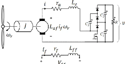
[image:2.595.317.537.581.694.2]Let us consider the wind energy conversion system in Figure 2. This system is based on a DC-Generator/Multiplier-Boost-Converter combination.
Fig. 2. Wind energy conversion system based on a separately excited DC-Generator connected to a DC-DC Multiplier Boost Converter.
(5)
(6)
(7) where is the duty cycle of the converter and the input of the dynamical system; is the sum of the converter inductance and the armature inductance ; is the
armature current, the mutual inductance of the
generator; the field current, an equivalent capacitance
of the multiplier converter; the number of capacitors at the output of the converter; the resistive load; the total inertia of the system; the torque that would be given by the wind turbine; , and the state variables which are the armature current, the output voltage and the rotor speed, respectively.
Let us rewrite equations (5)-(7) and use the rotor speed as the output of the dynamical system , this is
(8) where
;
Since the input multiplies some of the state variables in (8), it is clear that the dynamical system is nonlinear. Therefore, a nonlinear control technique is used for controlling the rotor speed of the wind turbine. In particular, input-output feedback linearization [6] is employed. The process of obtaining a subsystem that represents the input-output dynamics of the system includes to derive the input-output, this is
(9) where and are known as the Lie derivatives
of along the vectors and [6]. Using the definition in (9) and employing (8), the following expressions can be derived
therefore
(10) This state equation clearly corresponds to the rotor speed state equation since . Since the input is not involved in the first derivative of the output (see (10)), the second derivative is calculated, this is
(11) where
and
therefore
(12) Since the input is directly involved in the output second derivative, the following expression for the input is proposed
In this case
as
(14) Expression (14) is clearly a linear state equation. In order to obtain a linear state space representation for controlling the input-output subsystem, let us propose the following change of coordinates,
(15) In order to address system uncertainties, the following integrator is employed
(16) Where is the reference for the rotor speed. By employing equation (14) and (16) and considering the change of coordinates in (15), the following linear subsystem is obtained
(17) where the input can be defined by a linear control law based on the pole placement technique (see [12]), this is
(18)
IV. WIND SPEED ESTIMATION
A previous approach for the estimation of the wind speed in a wind energy conversion system was presented in [11]. In this paper, the wind speed estimation is extended for a wind energy conversion system based on a DC-Generator/Multiplier-Converter combination. An adaptive observer that has been proposed in [13] is employed. This approach considers the rotor speed and the armature current as measurable variables. Let us consider the following subsystem
(19) The wind turbine torque is given by [2],
(20) Thus, dynamic subsystem in (19) can be rewritten as
(21) State equation in (21) has the following form
(22) where is a set of measurable variables ( and in our case) and is an unknown parameter vector (the wind speed for this particular case). Therefore,
An adaptive observer for (22) that is able to estimate the non-measurable state variables and unknown parameters of the system was previously presented in [13]. It was derived to be applied to a class of cascade state affine systems. The equations of the observer are
(23) where and ; and are sufficiently large positive constants; is a bounded positive definite matrix. The gain associated to the estimation of the state vector of the system includes ; it is calculated as a solution of
(24) According to Fig. 1, the maximum power point is reached when . By considering equation (2) for the tip
speed ratio, the controller reference for the rotor speed in equation (16) is,
(25) It is clear that when the wind speed changes, the reference must change as well in order to track the optimal value of the power coefficient . By following the proposed methodology, we will consider the estimated wind speed
which was considered as an unknown parameter in
equation (22). Therefore,
(26) V. STABILITY OF THE CLOSED-LOOP SYSTEM
The stability of the linear subsystem (17) is accomplished by the adequate selection of gains , , . In other words, the input-output subsystem is stable if the standard closed loop matrix ( ) is a Hurwitz matrix. On the other hand, since the relative degree is equal to 2 and it is smaller than the order of the system, the internal dynamics of the system must be analyzed to ensure the stability of the full-order system [6]. For the purpose of analyzing the stability, the literature suggests to study the zero dynamics of the closed loop system. The zero dynamics is analyzed by selecting an initial condition for the output and a particular input that ensures that . This is,
(27) It is clear that the output will be zero for all . Then by following the conditions established in (27), the internal stability of the system will be analyzed. In other words, the stability of the state equations corresponding to the armature current and the output voltage will be verified.
Since and , the input of the system becomes,
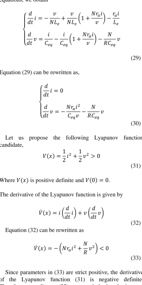
(28) By substituting the above input into the rest of the state equations, we obtain
(29) Equation (29) can be rewritten as,
(30) Let us propose the following Lyapunov function candidate,
(31) Where is positive definite and .
The derivative of the Lyapunov function is given by
(32) Equation (32) can be rewritten as
(33) Since parameters in (33) are strict positive, the derivative of the Lyapunov function (31) is negative definite. Therefore, according to (33), we conclude that the internal dynamics of the closed-loop system is stable.
VI. SIMULATION RESULTS
Simulation results of the wind speed estimation and the rotor speed of the wind energy conversion system are presented. The parameters for the simulation are; , , , ,
, , , ,
.The parameters of in (4) were employed. Figure 3 shows the wind speed compared to the estimation provided by the adaptive observer. The initial conditions for the observer are,
[image:5.595.306.546.104.584.2]Fig. 3. Wind speed and wind speed estimation.
[image:6.595.61.276.274.395.2]Figure 4 shows the simulation trace of the rotor speed that is controlled by using the estimated version of the wind speed. Figure 4 also shows the simulated optimal rotor speed that is calculated by using equation (2) and the actual rotor speed.
Fig. 4. Desired optimal rotor speed and simulation results of the controlled rotor speed.
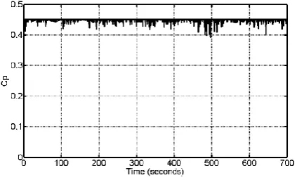
Figure 5 shows the transient behavior of the power coefficient as a function of the time. It is clear that the maximum optimum value in Fig. 1 is reached and tracked despite wind speed changes.
Fig. 5. Power coefficient in closed loop operation.
VII. CONCLUSION
This paper proposes an observer-based nonlinear control for a wind energy conversion system based on a DC-Generator and a Multiplier Boost Converter. The simulation results show the robustness of the controller regarding changes in the wind speed.
The presented methodology can be easily extended for other topologies that employ a state space approach. The use of a multiplier boost converter presents several advantages for wind energy conversion applications. In future works, a similar methodology may be employed for a brushless DC generator/ Multiplier Boost Converter combination.
REFERENCES
[1] Rosas-Caro, J.C.; Ramirez, J.M.; Peng, F.Z.; Valderrabano, A.; , "A DC-DC multilevel boost converter," Power Electronics, IET , vol.3, no.1, pp.129-137, January 2010.
[2] Iulian Munteanu, Antoneta Iuliana Bratcu, Nicolaos-Antonio, Cutululis, Emil Ceang, Optimal Control of Wind Energy Systems. Springer; 2008.Springer; 2008.
[3] Dehghan, S.M.; Mohamadian, M.; Varjani, A.Y.; , "A New Variable-Speed Wind Energy Conversion System Using Permanent-Magnet Synchronous Generator and Z -Source Inverter," Energy Conversion, IEEE Transactions on , vol.24, no.3, pp.714-724, Sept. 2009. [4] Kazmi, S.M.R.; Goto, H.; Hai-Jiao Guo; Ichinokura, O.; , "A Novel
Algorithm for Fast and Efficient Speed-Sensorless Maximum Power Point Tracking in Wind Energy Conversion Systems," Industrial Electronics, IEEE Transactions on , vol.58, no.1, pp.29-36, Jan. 2011. [5] Ching-Tsai Pan; Yu-Ling Juan; , "A Novel Sensorless MPPT Controller for a High-Efficiency Microscale Wind Power Generation System," Energy Conversion, IEEE Transactions on , vol.25, no.1, pp.207-216, March 2010.
[6] A. Isidori, Nonlinear Control Systems, 3rd ed. London, U.K.:Springer-Verlag, 1989.
[7] Wei Qiao, Wei Zhou, Jos M. Aller, and Ronald G. Harley, Wind Speed Estimation Based Sensorless Output Maximization Control for a Wind Turbine Driving a DFIG, IEEE Trans. onpower electronics, vol. 23, no. 3, 2008, pp.1156–1169.
[8] J. S. Thongam, P. Bouchard, H. Ezzaidi and M. Ouhrouche, Wind Speed Sensorless Maximum Power Point Tracking Control of Variable Speed Wind Energy Conversion Systems. Electric Machines and Drives Conference, 2009.
[9] Peter F. Odgaard, Chris Damgaard, Rasmus Nielsen, On-Line Estimation of Wind Turbine Power Coefficients Using Unknown Input Observers. IFAC. 2008.
[10] Hui Li, K. L. Shi and P. G.McLaren, Neural-Network-Based Sensorless Maximum Wind Energy Capture With Compensated Power Coefficient. IEEE Trans. on industry aplications, vol. 41, no. 6, 2005, pp.1548–1556.
[11] Salas-Cabrera, R.; Mayo-Maldonado, J.C.; De Leon-Morales, J.; Rosas-Caro, J.C.; Garcia-Guendulain, C.; Salas-Cabrera, N.; Castillo-Ibarra, R.; Gomez-Garcia, M.; Castillo-Gutierrez, R.; , "On the real time estimation of the wind speed for wind energy conversion systems," Electronics, Communications and Computer (CONIELECOMP), 2010 20th International Conference on , vol., no., pp.237-241, 22-24 Feb. 2010
[12] Franklin G.F., Powell J.D., Workman M.: Digital Control of Dynamic Systems. Addison Wesley, California (1997).
[13] M. Ghanes, G. Zheng and J. De-Leon, On simultaneous parameter identification and state estimation for cascade state affine systems.
Proc. of the American Control Conference, Seattle, WA, USA. 2008. pp. 45-50.
[14] P. C. Krause, O. Wasynczuk and S. D. Sudhoff, Analysis of Electrical Machinery and Drive Systems. John Wiley and Sons, IEEE Press Power Engineering; 2004.
[15] J. C. Mayo-Maldonado, R. Salas-Cabrera, H. Cisneros-Villegas, M. Gomez-Garcia, E. N. Salas-Cabrera, R. Castillo-Gutierrez and O. Ruiz-Martinez. “Modeling and Control of a DC-DC Multilevel Boost
Converter”. Proceedings of the World Congress on Engineering and Computer Science, San Francisco, USA. 2010.
[image:6.595.63.275.497.625.2]