1
Faculty of Electrical Engineering,
Mathematics & Computer Science
A Built-In Self-Test as a Countermeasure
for Fault Injection Attacks on
Cryptographic Devices
T.H. Redonet Klip B.Sc. Thesis
July 2018
Supervisors:
Problem Statement
Background
IV PROBLEMSTATEMENT
Problem Statement
In this Bachelor thesis, fault injection attacks on FPGA-based cryptographic implementations and appropriate countermeasures should be investigated. Known fault injection attacks, e.g. [4] [5] [6] should be considered and corresponding countermeasures should be developed. Possible countermeasures could be redundancy, CRC codes, or self-checking Lookup tables (LUTs) [5]. The developed countermeasures should be analyzed and implemented on an FPGA. The protection against to above mentioned attacks should be demonstrated. The following issues should be solved:
• Get familiar with the FPGA design flow and architecture.
• Setting up the fault injection attack for AES-based cryptographic implementations (see Master thesis Yuan Ji [5]).
• Literature research about countermeasures for the above mentioned attack.
• Developing countermeasures.
• Implement and test countermeasures.
• Evaluate the protection by the developed countermeasures.
Contents
Problem Statement iii
List of acronyms vii
1 Introduction 1
2 The Advanced Encryption Standard 3
3 Fault Injection Attacks 7
3.1 Differential Fault Analysis . . . 7
3.2 Differential Fault Analysis by Christophe Giraud . . . 8
3.3 Fault Injection Attack on a FPGA-based Cryptographic Implementation . . . . 10
4 Countermeasures for Fault Injection Attacks 13 4.1 General Countermeasures for FIAs . . . 13
4.2 Countermeasures for attacks on the FPGAs bitfile . . . 14
5 Built-In Self-Test as a Countermeasure 15 5.1 Concept . . . 15
5.2 Security Level . . . 16
5.3 Encryption and Authentication of the bitfile as a Countermeasure . . . 17
5.4 Overhead . . . 17
6 Implementation of the Built-In Self-Test 19 6.1 Implementation . . . 19
6.2 ZedBoard . . . 20
6.3 Vivado HLS . . . 20
6.4 Implementation of the Built-In Self-Test on the ZedBoard . . . 21
6.5 Overhead in the FPGA implementation . . . 22
List of acronyms
AES Advanced Encryption Standard
DES Data Encryption Standard
GF Galois Field
DFA Differential Fault Analysis
FIA Fault Injection Attack
FPGA Field Programmable Gate Array
LUT Lookup table
PCAP Processor Configuration Access Port
HMAC Hash Message Authentication Code
BIST Built-In Self-Test
HLS High Level Synthesis
ASIC Application Specific Integrated Circuit
Chapter 1
Introduction
FPGAs operate in a broad range of applications. An FPGA can solve any computable prob-lem. In fact, an FPGA is very similar to an Application Specific Integrated Circuit (ASIC). One of the applications where FPGAs are used is in cryptographic solutions. Encryption algorithms are designed to make messages unreadable for those who don’t have the se-cret key to decrypt the messages. Although the encryption algorithms may be unbreakable, several researchers [2] [4] [5] proved to crack the hardware implementations of these algo-rithms. FPGAs are amongst these hardware implementations as well. This indicates that there is a need for security on cryptographic devices.
The objective of this research is to investigate countermeasures for an attack on the bit-file of an FPGA which aims to extract the key of a cryptographic implementation. To be more specific, this research intents to counter the successful attack performed by Yuan Ji in his master’s thesis [5]. Several types of attacks are discussed and a working solution is proposed.
Chapter 2
The Advanced Encryption Standard
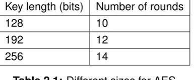
The Advanced Encryption Standard (AES) [7], successor of the Data Encryption Standard (DES), is a symmetric key cipher. Which means that it uses the same key for both encryption and decryption. AES is a modified version of the Rijndael Cipher [8]. The modified Rijndael Cipher was acknowledged as the encryption standard by the U.S. National Institute of Stan-dards and Technology in 2001 after Vincent Rijmen and Joan Dael won the contest for the new encryption standard back in January 1997. It is used in many applications worldwide because of its high speed, low need of memory and high security. The difference between AES and Rijndael is that AES only takes one size for the blocks of plaintext of 128 bits and three sizes for the keys, 128, 192, and 256 bits while Rijndael supports both variable block and key lengths. AES repeats a series of operations ten to fourteen times, depending on the key length which is specified in Table 2.1
Key length (bits) Number of rounds
128 10
192 12
[image:11.595.219.412.464.544.2]256 14
Table 2.1:Different sizes for AES
SubBytes
In this operation each byte is swapped with a byte from a predetermined table called the S-Box. The S-Box can be found in Appendix A.
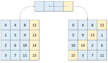
ShiftRows
[image:12.595.173.396.241.371.2]In the ShiftRows operation the 128-bit block is placed in a matrix of eight by eight bytes. Then each row is shifted 0, 1, 2, or 3 bytes. An example is illustrated in Figure 2.1
Figure 2.1:The ShiftRows operation.
MixColumns
The next operation is a bit more mathematically complicated. The importance in this step is the diffusion in the columns. This means that information in one byte gets smeared out over the rest of the column. The columns are transformed using a predetermined multiplication matrix. The coefficients of the multiplication matrix are chosen such that the transformation is fast and the diffusion is high. Instead of regular multiplication the matrices are multiplied in GF(28) [9], which treats the columns as 7th grade polynomials. Instead of additions, XOR
operations are used and overflows are corrected. The multiplication matrix is shown in Equa-tion 2.1 below.
y0 y4 y8 y11
y1 y5 y9 y13
y2 y6 y10 y14
y3 y7 y11 y15
=
2 3 1 1
1 2 3 1
1 1 2 3
3 1 1 2
×
x0 x4 x8 x11
x1 x5 x9 x13
x2 x6 x10 x14
x3 x7 x11 x15
(2.1) AddRoundKey
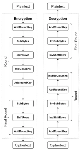
The Final Round
[image:13.595.174.452.206.719.2]In the last or final round of the encryption algorithm theMixColumns step is left out. This is because the algorithm is symmetric so the decryption is practically equivalent to the en-cryption, only with the functions inversed. The general encryption and decryption structure is illustrated in Figure 2.2
Chapter 3
Fault Injection Attacks
Encryption algorithms are designed to encrypt in such a way that it is impossible to reverse engineer the plaintext from the ciphertext. Furthermore, it is even impossible to reverse engineer the secret key when both the plaintext and the ciphertext are known. But if the en-cryption algorithm would malfunction, useful information about the key could be extracted. When an attacker makes the encryption algorithm malfunction intentionally, the attack is called a Fault Injection Attack (FIA). The goal of a FIA is to extract the secret key. This chap-ter discusses several methods to use the ciphertext with an induced fault to fully recover the key. Subsequently, an implementation of a FIA on an FPGA is discussed.
In this research, FIAs are subdivided in different types of attacks. Static transient fault injec-tion, dynamic transient fault injecinjec-tion, static permanent fault injection and dynamic perma-nent fault injection are evaluated in this research.
A transient fault is a fault which doesn’t induce permanent damage or modifications on the algorithm. A permanent fault is, logically, a fault which permanently alters the algorithm. A dynamically fault is a fault which is induced during runtime while a statically induced fault is induced before the algorithm starts.
3.1 Differential Fault Analysis
to occur, and that the fault in the encryption is random and caused by random hardware errors or by the user itself. This can be done by changing the supply voltage, exposing the circuit to electromagnetic radiation, changing the external clock frequency, tampering the circuit with a precise light beam, etc. Biham and Shamir did not demonstrate this in physical experiments but used the following fault model: the smartcard is assumed to have random faults with a small probability of occurrence in each bit. With other words, the model lets the attacker induce single bit error at a random location and time while the encryption is running. When the attacker lets the smartcard encrypt an unknown plaintext twice, the two ciphertexts won’t be equivalent if an error occurred in one of the two encryptions. Biham and Shamir deduced a lot of useful information and accomplished to extract the secret key from the DES algorithm by analyzing between 50 and 200 ciphertexts.
3.2 Differential Fault Analysis by Christophe Giraud
Christophe Giraud published an effective Fault Injection Attack (FIA) in 2005 called ’DFA on AES’ [4], because he found out that Biham and Shamir’s attack doesn’t work on AES. Giraud discusses two attacks based on two different fault models. The first fault model is based on a single bit error which is induced at the beginning of the final round. The second fault model is based on an induced fault which possibly changes a whole byte, but this fault model is out of the scope of this research and therefore the second attack too.
To assist the description of this attack, Giraud’s notations will be used:
• The plaintext is denoted byM and the key byK.
• The temporary cipher result after i encryption rounds is denoted by Mi and the jth
byte ofMi byMi j.
• Theith roundkey is denoted byKiand thejthbyte ofKibyKji.
• The correct ciphertext is denoted byCand thejthbyte ofC byCj.
• The faulty ciphertext is denoted byDand thejthbyte ofDbyDj.
• The intentionally induced bit error on thejthbyte ofMji is denoted byej.
The strategy of this attack is to extract M9 in order to deduce K10fromM9 andC. The full key can then be recovered by reversing the Rijndael Keyschedule algorithm [7] fromK10.
The final round transformsM9toCand consist of theSubBytesoperation, theShiftRows operation and finally and XOR-operation withK10. See Chapter 2.
So the following equation can be defined forC.
Next, some more notations will be adapted:
• The result of theSubBytesoperation on thejthbyte ofMjiis denoted bySubByte(Mji)
• The result of theShiftRowsoperation on thejthbyte ofMjiis denoted byShiftRow(Mji)
From Equation 3.1,CShif tRow(i)can be deduced as follows:
CShif tRow(i)=SubByte(Mi9)⊕KShif tRow10 (i),∀i∈ {0, ..,15} (3.2)
If a single bit errorej is induced onMj9,D with a one byte error is obtained. The non-zero
byte in C⊕D determines on which byte of M9 the single bit error was induced after an
inverseShiftRowsoperation onC⊕D. ThenDShif tRow(i)can be defined as well:
DShif tRow(i)=SubByte(Mi9⊕ej)⊕KShif tRow10 (i),∀i∈ {0, ..,15} (3.3)
Combining and reducing Equation 3.2 and 3.3 gives:
CShif tRow(j)⊕DShif tRow(j) =SubByte(j)(Mj9)⊕SubByte(Mj9⊕ej) (3.4)
Now that j is determined, Mj9 can be found. First, a set of possible values is found which
satisfy Equation 3.4 with a guessed position of the single bit errorej in Mj9. When this is
done with another faulty ciphertext, the correct value of Mj9 is expected to appear more
often. Giraud states that there is a 97% chance of determining a correct value ofM9
j with
three faulty ciphertext where the single bit errorej is induced on the same byte. Hence, the
3.3 Fault Injection Attack on a FPGA-based Cryptographic
Im-plementation
Figure 3.1: The location of the LUT to be flipped
[image:19.595.340.528.88.438.2]The netlist reveals which part of the hardware needs to modified in order to inject the error. Since theSubBytesoperation is the first opera-tion in the last encrypopera-tion round, the fault needs to be injected into the input of the S-Box. It turns out that an efficient way to implement AES on an FPGA is to replicate the S-Box block sixteen times, one for each byte in the (temporary) ci-phertext in order to process theSubByte oper-ation in parallel. Each of those sixteen S-Boxes has ten input groups, one for each encryption round. The error needs to be injected in the last input in one of those S-Boxes. Since the state of the input byte is determined by eight Lookup tables (LUTs), the truth table of one of the LUTs needs to be inverted to realize the fault injec-tion. To realize Giraud-based FIA, three different faulty ciphertext are needed to recover one byte of the key, so three LUTs need to be inverted per S-Box. This means that a minimal of forty-eight LUTs need to be inverted to fully recover the key. Figure 3.1 illustrates the location of the LUT to be inverted. The next step is to identify this LUT in the bitfile. The coordinates can easily be found in the netlist, but the attacker is assumed not to
Chapter 4
Countermeasures for Fault Injection
Attacks
In this chapter existing countermeasures for DFA are discussed. Countermeasures for gen-eral FIAs are treated. Subsequently, specific countermeasures for FIAs on an FPGAs bitfile are discussed.
4.1 General Countermeasures for FIAs
Several methods to inject faults in cryptographic devices require physical intrusions into the system. The attacker can use a directed light flash, laser or electromagnetic waves on an exposed circuit. An approach to defend the device against attacks like these can be to make the circuit physically inaccessible. This requires the housing of the circuit to be tamper-proof. For example through sensors that detect tampering with the housing. This method has been applied by IBM on their cryptographic processors [12].
For attacking methods which avoid the physical protection mentioned above, such as tem-pering with the supply voltage, the external clock, or the environmental temperature which cause the device to malfunction, there are hardware-based adjustments to counter them. One of those is to place the decryption process directly after the encryption. If the output of the decryption matches the original plaintext, no fault has been induced. However, this method has an overhead of over 100% on both space and time. A modification on this method can avoid this overhead. Two encryption processes either run in parallel on two pieces of hardware or in serial on the same piece of hardware. No fault is induced when the two ciphertexts match. However, the latter method will not work if the induced fault is permanent.
4.2 Countermeasures for attacks on the FPGAs bitfile
Chapter 5
Built-In Self-Test as a
Countermeasure
5.1 Concept
The countermeasures discussed in Section 4.1 don’t counter the attack on the bitfile or don’t provide enough protection against other types of FIAs. On the other hand, encryption and authentication is only available on some FPGAs. Besides, the attack on the bitfile executed by Ji [5] showed to be effective against encrypted bitfiles as well.
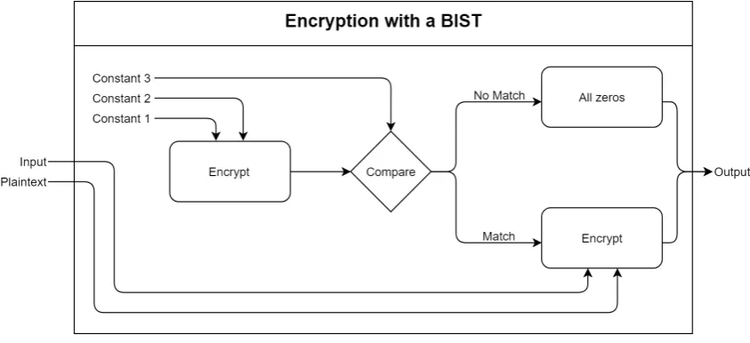
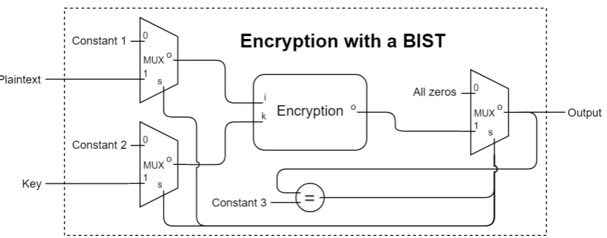
[image:23.595.103.525.516.709.2]This research proposes a countermeasure which protects cryptographic implementations against not only the type of attack described in Section 3.3 but several other attacks as well. This approach implements a Built-In Self-Test (BIST) on the encryption algorithm. The strategy is to encrypt a hardcoded plaintext with a hardcoded key and compare the output with a hardcoded pre-calculated output to legitimate the encryption algorithm. This check is prior to the encryption of the actual plaintext. The figure below illustrates this BIST.
Even though the fact that the goal of this countermeasure is to protect FPGAs against FIAs on the bitfile, the BIST can be implemented on other cryptographic devices as well. Since the BIST proves to be successfully implementable on an FPGA, it can be implemented on an ASIC too. In some aspects, ASICs might be more vulnerable for certain types of FIAs than FPGAs. Other types of attacks and for which the BIST is effective is discussed in the next section.
5.2 Security Level
The FIA discussed in section 3.3 is an example of a static permanent fault injection because the fault is injected before the FPGA is programmed and will occur at every encryption. The automated process of the FIA by Ji where the fault in the bitfile is induced during runtime through the PCAP is an exmaple of a dynamic permanent fault injection.
The BIST is not persistent against faults which are induced during the encryption of the plaintext. However, if the induced fault is permanent the attack will fail the second time. These attacks are a subset of the dynamically induced faults. The BIST will counter every other type of FIA, assumed that the attacker does not have any knowledge of the presence of the BIST. To verify if the BIST is working, the static FIA by Ji is executed. Since the BIST is implemented in a way that it will be active at every encryption, it can be assumed to be proved that the BIST will counter both of Ji’s FIAs on the bitfile. An overview of attacks which the BIST can counter is shown in Table 5.1.
Type of Attack Effective
Bitfile fault injection Yes
Transient fault injection before encryption Yes Transient fault injection during encryption No Permanent fault injection before encryption Yes
[image:24.595.107.462.456.557.2]Permanent fault injection during encryption At the second encryption
5.3 Encryption and Authentication of the bitfile as a
Counter-measure
Although Ji’s attack is successful even on an encrypted bitfile, the attack on an encrypted bitfile with a HMAC is still not possible. One could say that an authenticated encryption scheme might be sufficient. But P. Swierczynski et al. struggled with the same matter in their work Bitstream Fault Injections (BiFi)Automated Fault Attacks Against SRAM-Based FPGAs[14]. They found out that according to the annual reports only around fifty percent of the FPGAs that are sold from both Xilinx and Altera have bitstream authentication. So a large scale of FPGAs that are currently in use are not protected against attacks on the bitfile.
Since FPGAs can simply be programmed with the BIST, it can protect a larger scale of FPGAs. It is also worth noting that, as discussed, the BIST counters several other FIAs as well and that the BIST can be implemented on, for example, ASICs too.
5.4 Overhead
Chapter 6
Implementation of the Built-In
Self-Test
6.1 Implementation
[image:27.595.98.535.460.631.2]The implementation of the BIST is in hardware. The output is connected to a multiplexer which switches the output between the ciphertext and all zeros. The select line of the mul-tiplexer is connected to a comparator which checks the ciphertext computed from the hard-coded plaintext and key. This is illustrated in Figure 6.1. Since the implementation of the BIST is fairly simple and doesn’t need any elements which an encryption algorithm doesn’t have already, the BIST can be implemented on a lot of cryptographic devices.
In this research, the hardware is implemented on an FPGA. The platform used in this research is the ZedBoard. This board is equipped with an FPGA and a processing system. Both the implementation of the encryption with the BIST and the attack are executed on the ZedBoard.
6.2 ZedBoard
The Zedboard [11] is an educational development board. One if its features is its FPGA, the xc7z020 device. This FPGA is equipped with 53,200 LUTs and 106,400 flip-flops. Another feature on the ZedBoard is the on-board processing system. This can run programs writ-ten in C++ but more importantly, it can communicate with the FPGA via various interfaces. This makes it very feasible to develop the Fault Injection Attack on the FPGA for research purposes.
6.3 Vivado HLS
6.4 Implementation of the Built-In Self-Test on the ZedBoard
In this research, the BIST is implemented on the FPGA of the ZedBoard. To clarify this, the AES implementation in Ji’s research [5] was programmed in C++ [15]. The digital hard-ware implementation was generated using HLS. This was implemented on the xc7z020 device [11], where the ARM processor could perform the attack on the FPGA. The BIST is implemented using HLS as well. In the C++ code can be seen that the BIST function handles the input. This function performs the validity check before it encrypts the actual plaintext. The validity check is done by the following lines of code:
1 aes_core(&binput, &bkey, &aes_output);
2 if(aes_output == boutput){
3 aes_core(inptext, key, outtext);
4 }else{
5 *outtext = zero_output;
6 }
This if-statement legitimates the AES before it encrypts the plaintext. The variables binput, bkey, and boutput are the constants for the BIST. The variables inptext, key, and outtext are the input and output variables for the encryption. aes core is the actual encryption function.
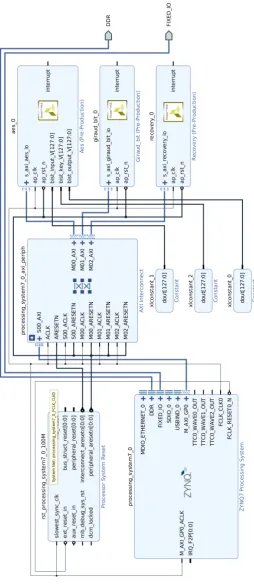
When the constants are simply hardcoded directly in the C++ code the implementation will not work. Vivado HLS aims to implement the code as efficient and optimized as possible. Since the tool doesn’t anticipate FIAs on the bitfile, the BIST will be seen as redundant and not be implemented at all. This is why the three constants need to be pulled out of the C++ code so that the HLS tool sees them as variables. The constants can then be inserted into the block design. The block design can be found in Figure 6.2.
For obvious reasons, the validity check needs to run on the same AES block as the actual encryption. The HLS tool tends to generate two separate hardware blocks if the same func-tion is called twice. This can be prevented and other preferences for hardware generafunc-tion can be added using pragmas [16]. To ensure that only one hardware block is generated for the encryption the following pragma is added:
1 pragma HLS allocation instances=aes_core limit=1 function
6.5 Overhead in the FPGA implementation
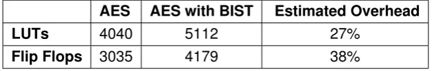
When no techniques are used to reduce the timing overhead, the BIST implementation lets the encryption take at least twice as long. But the BIST also needs additional circuitry. The FPGA needs LUTs and flip-flops to implement the BIST which gives overhead in hardware as well. The estimated overhead of the BIST implementation on the ZedBoard can be seen in Table 6.1.
AES AES with BIST Estimated Overhead
LUTs 4040 5112 27%
[image:30.595.128.443.204.256.2]Flip Flops 3035 4179 38%
Block Design of the Implementation in Vivado
Chapter 7
Evaluation on Security
This research also looked at possibilities to crack the BIST with a modified attack. For this hypothesis the attacker is assumed to have complete knowledge about the presence and functioning of the BIST. When looked at the internal hardware of the BIST a multiplexer switches the output between the ciphertext and all zeros. If the select line of the multiplexer is intentionally flipped while a fault is injected, the output will be the faulty ciphertext and the BIST will be cracked. Intuitively, one could expect that this select line is implemented as a LUT. In this case, the attacker would probably just execute the attack three times. The step attack would be to look for an all zeros output because that means that the BIST is activated. The next step would be to look for the LUT which changes the output from all zeros to a faulty ciphertext. At this point the attacker knows that the LUT which controls the BIST has been hit and that it has been cracked. The last step would be the attack on AES like the BIST is not there. Since all LUTs can be traversed in thirty minutes, the complete attack would at most take only ninety minutes. However, it turns out that a CARRY4 handles the select line and that the output of the CARRY4 goes to every output bit via an AND gate. So the BIST cannot be cracked using the LUT flipping method.
[image:33.595.97.532.623.672.2]If the bitfile were to be further reverse engineered to the point that LUTs can be modified instead of flipped, the BIST can be cracked. As mentioned before, whether the output will be the ciphertext or all zeros is determined by an AND gate for every output bit. These AND gates can be disabled when the attacker is able to modify the truth tables of LUTs. The output line of the CARRY4 which acts as the select line of the multiplexer needs to turn into a ’don’t care’ line. This is illustrated in the next figure.
Although this method seems feasible once the attacker figures out how to modify LUTs, there are some major uncertainties. The way to disable the BIST at every bit which takes the least amount of time is to try to find each AND gate one by one. Since finding one takes at most thirty minutes, disabling the whole BIST can take up to sixty-four hours. However, the attacker would only discover one of those AND gates if the output of the (faulty) ciphertext is one. When the output of the ciphertext is zero, the attacker wouldn’t notice any difference in the output bit and would miss the AND gate. The attacker would need multiple ciphertexts to find all one hundred twenty-eight AND gates to crack the BIST. This would take an ex-cessive amount of time.
Another method to crack the BIST would be to reverse engineer the bitfile so that the CARRY4 will malfunction. The attacker would need to decipher the complete working of the CARRY4 in the bitfile in order to force it to do the opposite of what it is supposed to do. However, at this level of reverse engineering of the bitfile it might be practical to aim directly at the key instead of a specific faulty ciphertext.
As discussed, there are several hypotheses to crack the BIST. However, the attacker would probably require to know the functioning of the BIST to successfully execute an attack. Even then, the attacker might have to traverse through massive search spaces.
Revision on the FIA by Yuan Ji
Chapter 8
Conclusions and Recommendations
The goal of this research was to investigate countermeasures for a Giraud-based Fault In-jection Attack (FIA) on the bitfile of an FPGA. A Built-In Self-Test (BIST) was successfully implemented on the Xilinx xc7z020 [11] and fully countered the FIA on the bitfile. As dis-cussed in Section 5.2, it is highly plausible that the BIST is effective against other types of FIAs as well.
This research also investigated possibilities to crack the BIST itself, assumed that the at-tacker has complete knowledge about the presence and the functionality of the BIST. It proved to be the case that it is not possible to extract a faulty ciphertext using a modified version of Ji’s LUT flipping method. Even when the attacker is able to partially modify a LUT, the attacker needs to traverse through an excessive search space. When the attacker chooses to abandon the LUT flipping method to crack the BIST, the bitfile needs to be re-verse engineered on a deeper level in order to be successful.
For further research purposes, the following concepts could be considered:
• Since the hardware is generated using High Level Synthesis (HLS), there is a lot of inessential circuitry which can be optimized away if the BIST is to be designed directly in Hardware Description Language (HDL).
• It might be beneficial to operate the encryption process, including the BIST, at double the clock frequency with respect to the rest of the system in order to achieve optimal security with minimal overhead.
Bibliography
[1] A. Barenghi, L. Breveglieri, I. Koren, and D. Naccache, “Fault injection attacks on cryptographic devices: Theory, practice and countermeasures,” Proceedings of IEEE, pages. 3056–3076, 2012.
[2] E. Biham and A. Shamir, “Differential fault analysis of secret key cryptosystems,” CRYPTO ’97 Proceedings of the 17th Annual International Cryptology Conference on Advances in Cryptology, pages. 513–525, Oct. 1996.
[3] D. Boneh, R. A. DeMillo, and R. J. Lipton, “Differential fault analysis of secret key cryp-tosystems,”CRYPTO ’97 Proceedings of the 17th Annual International Cryptology Con-ference on Advances in Cryptology, pages. 513–525, Aug. 1997.
[4] C. Giraud, “Dfa on aes,” International Conference on Advanced Encryption Standard, pages. 27–41, 2004.
[5] Y. Ji, “Protection of fpga-based cryptographic implementations against fault injection attacks,” Ph.D. dissertation, Friedrich-Alexander Universit¨at Erlangen-N¨urnberg, Dec. 2017.
[6] S. Raza, N. S. Malik, A. Shakeel, and M. I. Khan, “Implementation and comparative analysis of the fault attacks on aes,”nt. Arab J. Inf. Technol., pages. 625–634, 2013.
[7] F. I. P. S. 197,Advanced Encryption standard (AES). United States National Institute of Standards and Technology (NIST), November 26, 2001.
[8] J. Daemen and V. Rijmen,The Design of Rijndael. Springer -Verlag, 2002.
[9] C. J. Benvenuto, “Galois field in cryptography,” May 2012.
[10] M. M. Meier, “Untersuchung von fehlerinjektionsangriffen auf fpga-basierte kryp-tographische implementierungen,” Ph.D. dissertation, Technische Universit¨at Hamburg, Mar 2017.
[11] Xilinx, “Zynq-7000 all programmable soc technical reference manual,”Xilinx FPGA User Guide UG585.
[12] IBM, “Ibm 4764 pci-x cryptographic coprocessor specifications.” [Online]. Available:
[13] Xilinx, “Vivado 2017.2 release.”
[14] P. Swierczynski, G. T. Becker, A. Moradi, and C. Paar, “Bitstream fault injections (bifi)automated fault attacks against sram-based fpgas,” IEEE Transactions on Com-puters, 2017.
[15] B. Stroustrup,The C++ Programming Language, 1997.
Appendix A
AES: The S-Box
00 01 02 03 04 05 06 07 08 09 0A 0B 0C 0D 0E 0F
00 63 7C 77 7B F2 6B 6F C5 30 01 67 2B FE D7 AB 76
10 CA 82 C9 7D FA 59 47 F0 AD D4 A2 AF 9C A4 72 C0
20 B7 FD 93 26 36 3F F7 CC 34 A5 E5 F1 71 D8 31 15
30 04 C7 23 C3 18 96 05 9A 07 12 80 E2 EB 27 B2 75
40 09 83 2C 1A 1B 6E 5A A0 52 3B D6 B3 29 E3 2F 84
50 53 D1 00 ED 20 FC B1 5B 6A CB BE 39 4A 4C 58 CF
60 D0 EF AA FB 43 4D 33 85 45 F9 02 7F 50 3C 9F A8
70 51 A3 40 8F 92 9D 38 F5 BC B6 DA 21 10 FF F3 D2
80 CD C0 13 EC 5F 97 44 17 C4 A7 7E 3D 64 5D 19 73
90 60 81 4F DC 22 2A 90 88 46 EE B8 14 DE 5E 0B DB
A0 E0 32 3A A0 49 06 24 5C C2 D3 AC 62 91 95 E4 79
B0 E7 C8 37 6D 8D D5 4E A9 6C 56 F4 EA 65 7A AE 08
C0 BA 78 25 2E 1C A6 B4 C6 E8 DD 74 1F 4B BD 8B 8A
D0 70 3E B5 66 48 03 F6 0E 61 35 57 B9 86 C1 1D 9E
E0 E1 F8 98 11 69 D9 8E 94 9B 1E 87 E9 CE 55 28 DF
[image:39.595.100.555.281.568.2]F0 8C A1 89 0D BF E6 42 68 41 99 2D 0F B0 54 BB 16
Appendix B
Implementation in Vivado
The C++ code of the BIST and the Block Design in Vivado [13] can be found on the next pages. The BIST cannot be seen in the block design since it is implemented in the AES block and as mentioned before it is irrelevant to illustrate the insides of the AES block due to the extend of the circuit. However, the code of the BIST can be found in the Appendix B.1. In both the source code and the block design can be seen that the constants are not hardcoded. Instead constant blocks are connected to additional inputs of the AES block. This is because the HLS would optimize the BIST away since Vivado HLS [13] does not anticipate bitfile injection attacks. With other words, the BIST will not be implemented in the hardware at all.
B.1 Source code of the BIST
/ * −−−−−−−−−−−−−−−−−−−−−−−−−−−−−−−−−−−−−−−−−−−−−−−*
* B u i l t−In Self−Test
* Author : Tonino Redonet , U n i v e r s i t y of Twente * Date : June 2018
* To use the BIST , a c t i v a t e the f u n c t i o n below . * Make sure to comment the c o r r e c t s e c t i o n out * i n the f u n c t i o n above t h i s message .
* −−−−−−−−−−−−−−−−−−−−−−−−−−−−−−−−−−−−−−−−−−−−−−−* /
void aes ( a p u i n t<128> * i n p t e x t , a p u i n t<128> * key ,
a p u i n t<128> * o u t t e x t , a p u i n t<128> * b i s t i n p u t ,
a p u i n t<128> * b i s t k e y , a p u i n t<128> * b i s t o u t p u t ){
#pragma HLS INTERFACE s a x i l i t e p o r t =r e t u r n bundle= aes io #pragma HLS INTERFACE s a x i l i t e p o r t = i n p t e x t bundle= aes io #pragma HLS INTERFACE s a x i l i t e p o r t =key bundle= aes io #pragma HLS INTERFACE s a x i l i t e p o r t = o u t t e x t bundle= aes io #pragma HLS INTERFACE ap none p o r t = b i s t i n p u t bundle= b i s t i o #pragma HLS INTERFACE ap none p o r t = b i s t k e y bundle= b i s t i o #pragma HLS INTERFACE ap none p o r t = b i s t o u t p u t bundle= b i s t i o #pragma HLS PIPELINE
#pragma HLS a l l o c a t i o n instances =aes core l i m i t =1 f u n c t i o n
a p u i n t<128> aes output ;
a p u i n t<128> b i n p u t = * ( b i s t i n p u t ) ;
a p u i n t<128> bkey = * ( bist key ) ;
a p u i n t<128> boutput = * ( b i s t o u t p u t ) ;
a p u i n t<128> z e r o o u t p u t = a p u i n t<64>(0x0000000000000000 )
. concat ( a p u i n t<64>(0x0000000000000000 ) ) ;
aes core (& binput , &bkey , &aes output ) ; i f ( aes output == boutput ){
aes core ( i n p t e x t , key , o u t t e x t ) ; }else{
* o u t t e x t = z e r o o u t p u t ; }