Application of Active Suspension System to Reduce
Aircraft Vibration using PID Technique and Bees
Algorithm
Ali Reza Toloei
Department of Aerospace Shahid Beheshti UniversityTehran, Iran
Milad Zarchi
Department of Aerospace Shahid Beheshti UniversityTehran, Iran
Behrooz Attaran
Department of Mechanic Shahid Chamran UniversityAhwaz, Iran
ABSTRACT
The dynamic load and vibration caused by landing impact and the unevenness of runway will result in airframe fatigue, discomfort of crew/passengers and the reduction of the pilot’s ability to control the aircraft. The aim of the current paper is to design Proportional Integral Derivative classical controller based on Bees Intelligent Algorithm as the optimization techniquefor nonlinear model of active landing gear system that chooses damping and stiffness performance of suspension system at touchdown as optimization object. Optimal setting of controller parameters to achieve desirable time response using numerical software method based on Bees Algorithm is easier and more effective than other traditional methods because it does not need high experience and complex calculations and leads to better results. This research develops nonlinear two-dimensional mathematical model to describe landing gear system with oleo-pneumatic shock absorber and linear tire. Based on this model, the dynamic equations derived are used to investigate the behavior of an aircraft active landing gear system subject to runway disturbance excitation and the stability conditions of the landing system around static equilibrium position is studied according to the Routh-Hurwitz criterion.Simulink control system simulation software is utilized to validate the theoretical analysis of system stability and results comparison and adaptation of this paper with research of Wang and Xing about investigation of active landing gear system. Results of system numerical Simulation with optimized controller using Bees Algorithm in MATLAB software shows that the transmitted impact load to airframe, the vertical vibration of aircraft and time to return static equilibrium position at touchdown are significantly improved compared with other control performances.
General Terms
Classical Technique, Intelligent Optimization Algorithm
Keywords
Aircraft Active Landing Gear, PID Technique, Bees Algorithm
1.
INTRODUCTION
An aircraft landing gear system must absorb the kinetic energy produced by a landing impact and excitations caused by the aircraft travelling over an uneven runway surface. This is the necessary requirement of a successfully designed landing system [1-2]. The oleo-pneumatic shock strut is the most common type of shock absorber landing gear system used in aircrafts. It dissipates the kinetic energy produced by impacts arising when an airplane lands at high speed but also
offers a comfortable ride to passengers when the airplane taxies at low speed. The strut behaves in a strongly nonlinear manner, which influences the performance of the landing system [3-5]. From 1970s, the active control and semi-active control began to be popular and widely used in vibration control of constructions and vehicle suspensions. Compared with the passive control, the active and semi-active controls have excellent tunabilities due to their flexible structure.
Investigations [6-9] involving real-time feedback of the ground input to the landing system have shown that active control greatly reduces impact and fatigue loads experienced by the aircraft as well as vertical displacements. This is achieved by adjusting the system’s stiffness and damping values [6-9]. In most current airplane designs, a traditional passive landing gear system is used [10]. The impact loads experienced are large [11], because the characteristic design parameters of a shock-absorbing device in a passive system can not adjust to meet different landing and runway environments. In very bad landing conditions, large impact loads can reach the design limitations of the airframe and landing gear structure to cause a possible flight accident [11-12].
The development of shock absorber control technology is identified by passive, semi-active and active control phases [10]. The major difference between an active and a passive control landing gear system is that the hydraulic damping is changed following the shock strut stroke and the impact load [12]. This improves the performance of the active control shock absorber and the resulting vibration reduced by designing a suitable controller. Through measurement of the strut’s stroke, the controller influences a servo valve which regulates the damping characteristic and hence reduces the vibration [12].
for landing gear system at touchdown. Drop tests are carried out on an experimental passive landing gear system to validate the parameters of the simulation model. The result of numerical simulation shows that the isolation of impact load at touchdown can be significantly improved compared to other control algorithms. J.T. Xing [18] develops a mathematical model to control aircraft vibrations caused by runway excitation using an active landing gear system and focuses his paper on optimization of the performance of the active landing gear system. MATLAB simulation software is used to run simulations using a PID strategy.
The reminder of this paper is organized as follows: In section 2, the model of active landing gear is introduced. Then in section 3, PID control technique and Bees intelligent optimization algorithm is developed. Section 4 presents stability analysis of system. In section 5, the numerical simulation is performed and the conclusion of this investigation is summarized in sections 6.
2.
MODEL OF ACTIVE LANDING
GEAR SYSTEM
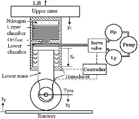
Figure 1 illustrates a model of an active landing gear system with a typical oleo-pneumatic shock absorber [18-20]. The absorber is the main component of a passive system. It consists of lower and upper chambers that these two chambers are connected by a small orifice. The upper volume of the top chamber is filled with pressurized nitrogen and the remaining volumes of the upper and lower chambers are filled with oil. This absorber design produces both spring and damping characteristics. During the process of an airplane landing, the shock strut experiences compression and extension. This motion forces the oil to pass through the orifice, which dissipates the large amount of energy created by a landing impact. The oil flows from the lower to the upper chamber, compressing the nitrogen that stores the remaining impact energy. When this stored energy is released, the shock strut extends and the oil flows from the upper to the lower chamber, thus dissipating the impact energy residue. This compression and extension oscillation continues until all landing impact energy dissipates. To this active landing gear system, an active control system is added as shown in Figure 1. The latter consists of a servo valve, a low-pressure (LP) reservoir, a high-pressure (HP) accumulator, a hydraulic pump, an electronic controller and feedback transducers. When an aircraft lands, the shock absorber stroke is influenced by the aircraft’s payload and varies depending on runway excitation. The stroke is measured by the transducers and their signals input into the electronic controller. This directs the servo valve to regulate the oil flow into or out of the shock absorber, hence producing the active control force to reduce the force transferred to the airplane. As will be shown, this action improves the performance of the passive system.
[image:2.595.317.544.72.266.2]To establish a mathematical model to describe the active landing gear system, the notations adopted are shown in Figure 2 [18]. Here, the airplane and possible attachments are simplified by a sprung concentrated mass m1 to which an aerodynamic lift L is applied. The suspension and tire systems are modelled by the unsprung concentrated mass m2. These two masses are connected by a spring with stiffness coefficient k1 and a damper with damping factor c1, which simulate the stiffness and damping of the shock strut unit. k2 and c2 stiffness and damping coefficients represent the stiffness and damping of the tire system, respectively.
[image:2.595.322.525.171.508.2]Fig. 1: Model of nonlinear landing gear with active control system
Fig. 2: Schematic sketch of the dynamic model of the active landing gear system
2.1 Dynamic Equilibrium Equations
Using Newton's second law of motion and the system model in Figure 2, we represent the dynamic equilibrium equations as
1 1 1
2 2 2
m y m g L Fa Fo f FQ
m y m g Ft Fa Fo f FQ
(1)
2.2 Shock Strut Force
[image:2.595.343.512.308.517.2]the tightness of the seal and the other friction force is due to the offset wheel.
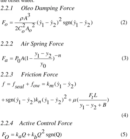
2.2.1
Oleo Damping Force
3
2
(
1
2
) sgn(
1
2
)
2
2
2
A
F
o
y
y
y
y
C Ao
o
(2)
2.2.2
Air Spring Force
1 2
(1 )
0
0
y y n
Fa P A y
(3)
2.2.3
Friction Force
( 1 2)
2
sgn( 1 2) ( 1 2) ( )
1 2
f fseal fow km y y
F Lt y y kn y y
y y B
(4)
2.2.4 Active Control Force
2 sgn(Q) FQ k Qa k Q
b
(5)
Where ka and kb are the two charactristic constants measured
for the servo valve system [12]. The flow quantity Q is calculated as follows [18]:
p p
sh sl Q C wxQ
(6)
Psh , Psl are pressure in the HP and LP reservoirs, respectively,
as shown in Figure 1, CQ represents a non-dimensional
discharge coefficient, w defines the orifice area gradient and x represent the displacement of the servo valve spool.
2.3 Tire Force
In order to simplify the mathematical model, the tire is acted as a combination of a linear spring and a linear damper as follows [21]:
(
2
)
(
2
)
F
t
c y
t
y
g
k
t
y
y
g
(7)
3.
CONTROLLER DESIGN
Classical controller accounts for more than 90% of the controls and automation applications today, primarily because effective and simple to implement. They originally are intended for linear, time-invariant systems. This type of controller has developed, to control systems with more complex dynamics. For linear systems and some nonlinear systems, classic controllers such as PI, PD and PID have been widely used in industrial control processes.
3.1 Introduction of PID Controller
Proportional Integral Derivative Controller (PIDC) is used where system is second-order or high order. It ensures set point tracking with zero steady state error and allows faster response without oscillatory nature of PI control greater influence of error response, degree of overshoot and oscillation.
The displacement of servo valve spool is controlled by classical method as shown in figure 3. The classical controllers have the advantage of being structurally simple, mathematically credible, more or less easy to realize with scope for adjustment, thus making it widely applicable in
[image:3.595.53.282.87.332.2]engineering systems. These control methods are chosen to complete the mathematical model and to investigate the landing gear system’s performance.
Fig. 3: Schematic sketch of the PID classical controller
In Figure 3, r represents a reference signal and y is the feedback signal measured from the landing gear by transducers. Their difference e is input into the classical controllers. The transfer functions of PID controller is defined as follows:
( )
( )
( )
k
U s
i
C s
k
p
k s
d
E s
s
(8)
Here, kp represents a proportionality coefficient, ki an integral
coefficient and kd a differentional coefficient. These feedback
coefficients can be adjusted to obtain the best control efficiency. The output signal of the controller gives the displacement x of servo-valve spool as follows:
( ) { ( ) ( )} { ( ) ( )} { ( ) ( )} x t kp r t y t k r ti y t kd r t y t
(9)
3.2. Introduction of Bees Algorithm
During the harvesting season, a colony of bees keeps a percentage of its population as scouts [22] and uses them to explore the field surrounding the hive for promising flower patches. The foraging process begins with the scout bees being sent to the field where they move randomly from one patch to another.
Algorithm. For more details, the reader is referred to [28]. The algorithm requires a number of parameters to be set, namely: number of scout bees (n), number of sites selected for neighborhood searching (out of n visited sites) (m), number of top-rated (elite) sites among m selected sites (e), number of bees recruited for the best e sites (nep), number of bees recruited for the other (m-e) selected sites (nsp), the initial size of each patch (ngh) (a patch is a region in the search space that includes the visited site and its neighborhood), and the stopping criterion.. Figure 5 represents schematic sketch of the classical controller with Bees Algorithm. The objective function of optimization problem is introduced in Equation 10.
Fig. 4: Flowchart of the Bees Algorithm (BA)
Fig. 5: Schematic sketch of the PID-BA controller
( ) 0 T
ITAE t e t dt
(10)
4.
STABILITY ANALYSIS
We assume that, in time, the aircraft returns to its static equilibrium position after a landing impact or a runway excitation. A passive landing gear satisfies this assumption. As shown in figure 1, an active landing system is established by using of an active control unit. This unit provides additional damping and stiffness forces to improve the performance of the passive landing gear system. these additional forces play a modifying role with the expectation that they cause the aircraft to return to its static equilibrium position quicker than by the passive landing gear system. Furthermore, these forces cause the less impact to induce to
aircraft’s airframe than by the passive landing gear system only.
4.1 Static Equilibrium Solution
To determine the static equilibrium solution of the landing gear system, the time derivatives of the displacements y1 and
y2, the ground inputs and its time derivative are set to zero
[18]. This allows Equation 1 reduce to
1 1
2 2
m y
F
a
F
o
f
m y
F
t
F
a
F
o
f
(11)
4.2 Dynamic Equations Around the Static
Equilibrium Solution
By using Taylor's expansion around static stroke of shock absorber and neglecting higher-order quantities, the term arising Equation 11 is derived as follow
4.2.1 Oleo Damping Force
0
Fo
(12)
4.2.2 Air Spring Force
( )( )
0 0 1 2
n
Fa p A y y
y
(13)
4.2.3 Friction Force
( 1 2)f km y y
(14)
4.2.4 Active Control Force
F
Q
k Q
a
(15)
4.3 Stability Conditions
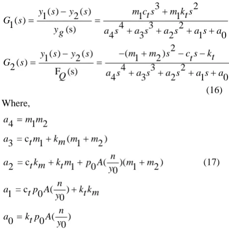
By substitution of linearized Equations in Equation 11 and taking Laplace transform, the transfer functions of system are derived as follow
3
2
( )
( )
1
2
1
1
( )
1
(s)
4
3
2
4
3
2
1
0
2
(
)
( )
( )
1
2
1
2
( )
2
F (s)
4
3
2
4
3
2
1
0
y s
y
s
m c s
t
m k s
t
G s
y
g
a s
a s
a s
a s
a
m
m
s
c s
k
y s
y
s
t
t
G
s
a s
a s
a s
a s
a
Q
(16) Where,
4 1 2
= c ( )
3 1 1 2
= c ( )( )
2 1 0 0 1 2
= c ( )
1 0 0
( )
0 0 0
a m m
a tm km m m n
a tkm k mt p A m m y
n
a tp A k kmt y
n a k p At
y
(17) [image:4.595.314.548.477.711.2]
( ).
1
(s)
1
2
3
2
(
1
1
)
.
4
3
2
1
4
3
2
1
0
3
4
min{
,
}
1
1
3
2
min{
,
}
1
1
2
1
min{
,
}
1
1
C s G
k s
p
k
i
k s
d
m c s
t
m k s
t
s
a s
a s
a s
a s
a
a
a
k
d
m c
t
m k
t
a
a
k
p
m c
t
m k
t
a
a
k
i
m c
t
m k
t
(18)( ).
2
(s)
1
2
2
(
1
2
)
.
1
4
3
2
4
3
2
1
0
3
2
1
max{
,
,
}
(
1
2
)
0
2
1
max{
,
,
}
(
1
2
)
0
1
max{
,
, 0}
(
1
2
)
C s G
k s
p
k
i
k s
d
m
m
s
c s
t
k
t
s
a s
a s
a s
a s
a
a
a
a
k
d
m
m
c
t
k
t
a
a
a
k
p
m
m
c
t
k
t
a
a
k
i
m
m
ct
(19)5.
NUMERICAL SIMULATION
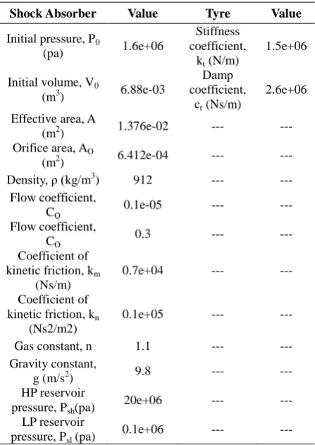
SIMULINK control system simulation software derives numerical simulations of the active landing gear system responses. We investigate A6 Intruder airplane with values according to Table 1 and Parameters of the Bees Algorithm are given in Table 2. Aircraft and Landing gear masses are 4832.7 kg and 145.1 kg, respectively. Lift Aerodynamic Force is 7500 N and Touchdown velocity is 78 m/s and runway disturbance is half sin-type ramp of height 10cm and time 0.4s over which the airplane travels. As derived from [18], the parameters defining the stability conditions are given by
1.680
5
1.23 10
1.601
1.042
k p
ki
k
d
(20)
TABLE 1: Data used in the simulation Shock Absorber Value Tyre Value Initial pressure, P0
(pa) 1.6e+06
Stiffness coefficient,
kt (N/m)
1.5e+06
Initial volume, V0
(m3) 6.88e-03
Damp coefficient,
ct (Ns/m)
2.6e+06
Effective area, A
(m2) 1.376e-02 --- ---
Orifice area, AO
(m2) 6.412e-04 --- ---
Density, ρ (kg/m3
) 912 --- ---
Flow coefficient, CQ
0.1e-05 --- ---
Flow coefficient, CO
0.3 --- ---
Coefficient of kinetic friction, km
(Ns/m)
0.7e+04 --- ---
Coefficient of kinetic friction, kn
(Ns2/m2)
0.1e+05 --- ---
Gas constant, n 1.1 --- ---
Gravity constant,
g (m/s2) 9.8 --- ---
HP reservoir pressure, Psh(pa)
20e+06 --- ---
LP reservoir pressure, Psl (pa)
[image:5.595.54.287.71.392.2] [image:5.595.317.541.81.397.2]0.1e+06 --- ---
TABLE 2: Data used in the Bees Algorithm Case 1 (without runway disturbance) Value
N 100
M 15
E 4
Nep 12
Nsp 5
Ngh 50
Case 2 (with runway disturbance) Value
N 80
M 10
E 4
Nep 10
Nsp 4
5.1 RESULTS AND DISCUSSIONS
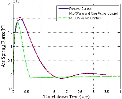
Three kinds of control methods including passive control, PID-Wang & Xing active control and PID-Bees Algorithm active control are used in the computer simulation. In the process of simulation, the comparison is taken in terms without disturbance and with disturbance of runway.
[image:6.595.63.263.164.326.2]5.1.1 Case 1: Results without Runway Disturbance
[image:6.595.323.523.244.405.2]Fig. 6: The vertical vibration of aircraft with
y
1 optimization objective functionFig. 7: The vertical vibration of aircraft with
y
s optimization objective functionThe vertical displacement of the aircraft is an important parameter in designing an aircraft landing gear system. It is expected that an aircraft rapidly returns to its original equilibrium state without runway disturbance. Through numerical simulation and according to the parameters defining the stability conditions, we found that the approximate optimum set in Bees Algorithm produced the best control efficiency. Figures 6 and 7 show that there is 7% and 27% decrease of the aircraft’s displacement response, respectively, making taxiing smoother and therefore the crew/passenger comfort improved. The passive system requires approximately 3s for the aircraft to return to its static equilibrium position. This time is reduced to approximately 1s using active system with PID controller and Bees Algorithm that demonstrates a significant improvement over the performance of the passive system.
[image:6.595.63.261.352.526.2]Fig. 8: The air spring force with
y
1optimization objective function [image:6.595.323.522.443.612.2]The amplitude of the spring force transmitted to the airframe and landing gear affects the structural strength and the fatigue life of them. Figures 8 and 9 show that this force is reduced using the PID-BA active system and indicate that there is 11% and 33% decrease of the transmitted force in the passive landing gear respectively, if this system is used that results in improvements to the longevity of the airframe and landing gear and comfort to passengers.
[image:7.595.60.262.179.346.2]5.1.2 Case 2: Results with Runway Disturbance
[image:7.595.317.522.258.411.2]Fig. 10: The vertical vibration of aircraft with
y
1 optimization objective functionFig. 11: The vertical vibration of aircraft with
y
s optimization objective function [image:7.595.61.260.356.543.2]The vertical displacement of the aircraft is an important parameter in designing an aircraft landing gear system. It is expected that an aircraft rapidly returns to its original equilibrium state when influenced by a runway disturbance. Through numerical simulation and according to the parameters defining the stability conditions, we found that the approximate optimum set in Bees Algorithm produced the best control efficiency. Figure 11 shows that there is a 18% decrease of the aircraft’s displacement response with optimization objective function of shock absorber stroke velocity, making taxiing smoother and therefore the crew/passenger comfort improved. The passive system requires approximately 3s for the aircraft to return to its static equilibrium position. This time is reduced to approximately 2s using active system with PID controller and Bees Algorithm that demonstrates a significant improvement over the performance of the passive system as shown in Figure 11.
Fig. 12: The air spring force with
y
1optimization objective function [image:7.595.318.522.452.621.2]The amplitude of the spring force transmitted to the airframe and landing gear affects the structural strength and the fatigue life of them. Figures 12 and 13 show that this force is reduced using the PID-BA active system and indicate that there is 7% and 27% decrease of the transmitted force in the passive landing gear respectively, if this system is used that results in improvements to the longevity of the airframe and landing gear and comfort to passengers.
6. CONCLUSION
Comparison of passive control, PID-Wang & Xing active control and PID-Bees Algorithm active control in two cases (without disturbance and with disturbance) identify the effectiveness of the third through significant reduction in the magnitude of the displacement of the center of gravity of the aircraft and the load transmitted to the airframe by the landing gear during aircraft landing. It is further demonstrated that by using an active landing gear system, a reduction in the time length of responses to return to their static equilibrium positions is achieved, thus improving the performance of the landing gear, the fatigue life of the airframe and landing system, crew and passenger comfort, the pilot’s ability to control the airplane during ground operations and a reduction of the influence of runway unevenness. This study provides a theoretical and numerical approach to initiate the design of a realizable active landing gear system. The linearized equations are used here to study the stability of a nonlinear system about static equilibrium point.
7. REFERENCES
[1] N.S. Currey, “Aircraft landing gear design: principles and practices, AIAA Education Series, AIAA (1998). [2] R. Freymann, “Actively damped landing gear system,
Landing Gear Design Loads Conference, No.20,
AGARD CP-484, 1991. [3] R. Freymann, “An experimental–analytical routine for
the dynamic qualification of aircraft operating on rough runway surfaces, AGARD R-731 (1987).
[4] T. Catt, D. Cowling, A. Shepherd, “Active landing gear control for improved ride quality during ground roll, SDL Report No. 232, Stirling Dynamics Limited, 1992. [5] T.W. Lee, “Dynamic response of landing gears on rough
repaired runway, Menasco Aero Systems Division (1998) 124–135.
[6] I. Ross, R. Edson, Application of active control landing gear technology to the A-10 aircraft, NASA CR-166104 (1983).
[7] W.E. Howell, J.R. Mc Gehee, R.H. Daugherty, W.A. Vogler, F-106B airplane active control landing gear drop test performance, Landing Gear Design Loads Conference No. 21, AGARD CP-484, 1991.
[8] C.H. Lucas, Modeling and validation of a navy A6-intruder actively controlled landing gear system, NASA TP-209124 (1999).
[9] I. Ross, R. Edson, An electronic control for an electro hydraulic active control landing gear for the F-4 aircraft, NASA CR-3552 (1982).
[10] I.P. Jocelyn, An overview of landing gear dynamics, NASA TM-209143 (1999).
[11] B.W. Payne, A.E. Dudman, B.R. Morris, M. Hockenhull, Aircraft dynamic response to damaged and repaired runways, AGARD CP-326 (1982).
[12] Y.H. Jia, Taxiing performance analysis of active
control of landing gear, Acta Aeronautica et Astronautica Sinica 20 (6) (1999)545–548.
[13] G.L. Ghiringhelli, Testing of semiactive landing gear control for a general aviation aircraft, Journal of Aircraft 37 (4) (2000) 607–616. [14]
[14] D. Karnopp, Active damping in road vehicle suspension system, Vehicle Systems Dynamics 12 (6) (1983) 291–316.
[15] R.M. Goodall, Active controls in ground transportation, A review of the state-of-the-art and future potential, Vehicle Systems Dynamics 12 (4) (1983) 225–257.
[16] J.K. Hedrick, The application of active and passive suspension techniques to improve vehicle performance, Final Report, US Department of Transportation, Contract DTRS5680-C-00018, 1983.
[17] WU Dong-su, GU Hong-bin, LIU Hui. GA-Based Model Predictive Control of Semi-Active Landing Gear. Chinese Journal of Aeronautics 20(2007) 47-54.
[18] Haitao Wang, J.T. Xing, W.G. Price, Weiji Li. An investigation of an active landing gear system to reduce airceaft vibeations caused by landing impacts and runway excitations. Journal of Sound and Vibration 317(2008)50-66.
[19] D.L. Xu, Y.R. Li, Mathematical model research on aircraft landing gear, Journal of System Simulation 17 (4) (2005) 831–833.
[20] P. Jin, H. Nie, Dynamic simulation model and parameter optimization for landing gear impact, Journal of Nanjing University of Aeronautics & Astronautics 35(5)(2003) 498–502.
[21] E. Bakker, H.B. Pacejka, L. Linder, New tire model with an application in vehicle dynamic studies, Progress in Technology 57 (1995)439–452.
[22] Leite J.P.B. and Topping B.H.V. “Improved Genetic Operators for Structural Engineering Optimization”. Advances in Engineering Software, 1998. 29(7-9): pp. 529-562.
[23] Seeley T.D. “The Wisdom of the Hive: The Social Physiology of Honey Bee Colonies”. Cambridge, Massachusetts; Harvard University Press. 1996
[24] Von Frisch K. Bees: Their Vision, Chemical Senses and Language. Revised Edition, Ithaca, N.Y.: Cornell University Press.1976
[25] Camazine S., Deneubourg J.-L., Franks N.R., Sneyd J., Theraula G., and Bonabeau E. Self-Organization in Biological Systems. Princeton: Princeton University Press.2003
[26] Bonabeau E., Dorigo M., and Theraulaz G. Swarm Intelligence: from Natural to Artificial Systems. New York: Oxford University Press.1999
[27] Karaboga D. An Idea Based on Honey Bee Swarm for Numerical Optimization. Turkiye: Erciyes University, Engineering Faculty, Computer Engineering Department. Technical Report. TR06.2005