SC-FDMA based Systems to Reduce PAPR by using a
Modified Commanding Scheme
Sajjan Singh
12
Ph.D Research Scholar Department of Electronics & Communication Engineering Lingaya’s University Faridabad,
India
Pardeep
21
M.Tech Research Scholar Department of Electronics & Communication Engineering
BRCM CET, Bahal Bhiwani, India
S. V. A. V. Prasad
33
Professor
Department of Electronics & Communication Engineering
Lingaya’s University Faridabad, India
ABSTRACT
The 3rd generation partnership project (3GPP) long term evolution (LTE) standard uses single carrier frequency division multiple access (SCFDMA), scheme for the uplink transmissions and orthogonal frequency division multiplexing access (OFDMA) in downlink. SCFDMA makes use of single carrier modulation and frequency domain equalization, it is a technique that has similar performance and essentially the same overall complexity as those of OFDM, But in OFDMA high peak-to-average power ratio (PAPR) is a major drawback. An outstanding advantage of SC-FDMA is its lower PAPR due to its single carrier structure. In this paper, we analyze the PAPR of SC-FDMA signals with pulse shaping. We analytically derive the time domain SC-FDMA signals and numerically compare PAPR characteristics using the complementary cumulative distribution function (CCDF) of PAPR. The results show that SC-FDMA signals indeed have lower PAPR compared to those of OFDMA. Comparing the two forms of SC-FDMA, we find that localized FDMA (LFDMA) has higher PAPR than interleaved FDMA (IFDMA) but somewhat lower PAPR than OFDMA. Also noticeable is the fact that pulse shaping increases PAPR. To reduce the PAPR, we propose an efficient Kalman filter based PAPR reduction algorithm.
Keywords
OFDMA, SC-FDMA, IFDMA, LFDMA, PAPR, Kalman Fil;ter
1.
INTRODUCTION
Today demands for media-rich wireless data services have brought much attention to high speed broadband mobile wireless techniques in recent years. Orthogonal frequency division multiplexing (OFDM), which is a multicarrier communication technique, has become widely accepted primarily because of its robustness against frequency selective fading channels which are common in broadband mobile wireless communications. Orthogonal frequency division multiple access (OFDMA) is a multiple access scheme which is an extension of OFDM to accommodate multiple simultaneous users. Furthermore, by adding the cyclic prefix in an OFDM symbol as the guard interval, it can reduce the inter-channel interference (ICI) and inter-symbol inference (ISI).
Long term evolution (LTE) is standardized by the third generation partnership project (3GPP) and is an evolution to existing 3G technologies in order to meet projected customer needs over the next decades. 3GPP LTE uses orthogonal
PTS algorithm, and the SLM algorithm, have relatively good performance in regards to the out-of-band interferences and information transfer rate, but signal shape degrades [13,14].
2.
OVERVIEW OF SC-FDMA SYSTEM
MODEL
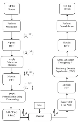
[image:2.595.44.301.262.662.2]A simplified block diagram of the SC-FDMA transceiver is depicted in Figure 1. Figure 1 illustrates the transmitter and receiver structure of SC-FDMA system. At the transmitter side, a baseband modulator transmits the binary input to multilevel sequences of complex number
{
x
n( )p}
in one of several possible available modulation formats, such as Quadrature Phase Shift Keying (QPSK), and Quadrature Amplitude Modulation (QAM), etc [7]. The transmitter next groups the modulation symbols,x
n( )p into blocks each containing N symbols.Fig 1: Transmitter and Receiver structure of an SC-FDMA system model.
The first step in modulating the SC-FDMA subcarriers is to perform an N-point discrete Fourier transform (DFT), to produce a frequency domain representation
X
k( )p of the input symbols as given by (1). ). It then maps each of the NDFT outputs to one of the M (> N) orthogonal subcarriers that can be transmitted. Typically, N = M/Q is an integer sub multiple of M. M represents the total number of available subcarriers, where M = Q.N. Q is the bandwidth expansion factor of the symbol sequence. For example, if all terminals transmit N symbols per block, the system can handle Q simultaneous transmissions without co-channel interference. We further assume that each user occupies the same number of subcarriers, so in this case Q also represents the number of users. Each user p,
p
0,1,....,
Q
1
generates a block of N complex-valued symbolsx
n( )p where0,1,...,
1
n
N
. By applying an N-point DFT tox
n( )p , the frequency domain symbolsX
k( )p can be described as:2
1 ( )
( ) ( )
0
N j kn
p p N
k n
n
X
x
e
….. (1)
The frequency domain symbols are then mapped onto a set of user-dependent subcarriers [10]. The result of the subcarrier mapping is the set of complex subcarrier amplitudes, where N of the amplitudes are non-zero. As in OFDMA, an M-point inverse FFT (IFFT) transforms the subcarrier amplitudes to a complex time domain signal. Each then modulates a single frequency carrier and all the modulated symbols are transmitted sequentially [8].
The transmitter performs two other signal processing operations prior to transmission. It inserts a set of symbols referred to as a cyclic prefix (CP) in order to provide a guard time to prevent inter-block interference (IBI) due to multipath propagation. The transmitter also performs a linear filtering operation referred to as pulse shaping in order to reduce out-of-band signal energy [9].
There are M subcarriers, among which N (< M) subcarriers are occupied by the input data. In the time domain, the input data symbol has symbol duration of T seconds and the symbol duration is compressed to
~
(
N
).
T
T
M
after goingthrough SC-FDMA modulation [11]. There are two methods to choose the subcarriers for transmission as shown in Fig. 2.
(a) Distributed Mode Noise
I/P Bit Stream
Perform Modulation
N-point DFT
Apply Subcarrier
Mapping
M-point IFFT
PAPR Normalization using
Companding
Add CP (+)
& DAC Channel
O/P Bit Stream
Perform Demodulation
N-point IDFT
Apply Subcarrier Demapping &
Frequency Domain Equalization (FDE)
M-point FFT
Remove CP (-) & ADC ( )
{
x
n p}
( )
{
X
k p}
~ ( )
{
X
l p}
( ) ~
{
}
p m
x
*RU#: Resource Unit Number RU#0 RU#1 RU#2 RU#3
(b) Localized Mode
Fig. 2: Frequency Domain Representation of SC-FDMA system: Distributed mode, (b) Localized mode. An
example of M=16, Q=4 and N=4
Figure 2 shows an example of a frequency division multiple access schemes with distributed and localized subcarrier mapping. There are 16 (M=16) available subcarriers shared by 4 (Q=4) users and each user occupies 4 (N=4) subcarriers. Each user must map its frequency domain symbols onto the assigned resource unit (RU) and zeros are inserted for the remaining subcarriers. In DFDMA, the RU for each user is a set of interleaved subcarriers across the available transmission band. DFDMA is robust against frequency selective fading since it better exploits the available frequency diversity [10]. In LFDMA, the RU for each user is a set of adjacent subcarriers. LFDMA can potentially achieve multiuser diversity if for each user the localized section of allocated bandwidth experiences high channel gain. This form of multiuser diversity requires independent frequency selective fading per user combined with intelligent radio resource unit allocation [10]. In the distributed subcarrier mapping mode, DFT outputs of the input data are allocated over the entire bandwidth with zeros occupying in unused subcarriers, whereas consecutive subcarriers are occupied by the DFT outputs of the input data in the localized subcarrier mapping mode. We will refer to the localized subcarrier mapping mode of SC-FDMA as localized FDMA (LFDMA). The case of M = Q. N for the distributed mode with equidistance between occupied subcarriers is called Interleaved FDMA (IFDMA) [11].
0
x
x
1x
2x
3 [image:3.595.318.542.136.269.2]? ? ? ? ? ? ? ? ? ? ?
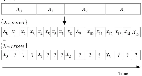
Fig. 3 An example of SC-FDMA transmit symbols in the time domain for N = 4, Q = 4 and M = 16.
An example of SC-FDMA transmit symbols in the time domain for N = 4, Q = 4 and M = 16 is illustrated in figure 3. After subcarrier mapping, the frequency data is transformed back to the time domain by applying inverse FFT (IFFT).
The frequency domain samples
~ ( )
{
p}
l
X
after the subcarrier mapping process (Distributed and Localized) are represented by equations (2) and (3) respectively:Where l represents the subcarrier index going into the M-point IFFT,
l
0,1,....,
M
1
and p is the resource unit number (RU#). It should be noted that p can also denote the user index, i.e.p
0,1,....,
Q
1
. After subcarrier mapping,the sampling period
~
T
is reduced, i.e.~
(
N
). ,
T
M
T
where T is user input symbol period. The frequency domain samples
{
X
l( )p}
are transformed back into the time domain by an M-point IDFT. The output time domain samples of SC-FDMA before the application of pulse shaping can generally be described by equation (4):3.
PAPR OF SC-FDMA SIGNALS
In this section, we analyze the PAPR of the SC-FDMA signal for each subcarrier mapping mode. For distributed subcarrier mapping mode, we will consider the case of IFDMA. In the subsequent derivations, we will assume M = Q. N.
Let
{
x
n:
n
0,1,....,
N
1}
be data symbols to be modulated. Then,{X : k
k
0,1,....,
N
1}
are frequency domain samples after DFT of{
x
n:
n
0,1,....,
N
1}
,( ) ~
{
:
0,1,...., M 1}
p
l
X
l
are frequency domainsamples after subcarrier mapping, and
~
{
x
m: m
0,1,..., M 1}
are time symbols after IFFT of( ) ~
{
:
0,1,...., M 1}
p
l
X
l
. The complex pass bandtransmit signal of SC-FDMA
x t
for a block of data is represented as:0 1 2 3 4 5 6 7 8 9 10 11 12 13 14 15 Subcarrier Index
0
x
x
1x
2x
3x
4x
5x
6x
7x
8x
9x
10x
11x
12x
13x
14x
150
x
x
1x
2?
x
3~
{
x
m}
~ ,
{
x
m IFDMA}
~ ,
{
x
m LFDMA}
Time
2
( ) 1 ~
~ ( )
( ) 0
1
p M j ml
p M
m l
l
x
X
e
M
( )
~
pl
X
( ) ( ) ( ),
p p
k l Np
X X l k Np
0 ,
otherwise
……. (3)
……. (4)
( )
~
pl
X
( ) ( ) ( )/ ,
p p
k l p Q
X X l Qk p
0 ,
otherwise
……. (2)
1 ~ ~
0
( )
c(
)
M j t
m m
x t
e
x r t
mT
[image:3.595.46.291.542.673.2]Where cis the carrier frequency of the system and r(t) is the baseband pulse. In our research, we use a raised-cosine pulse, which is a widely used pulse shape in wireless communications, defined as follows in the time domain [11, 12].
~
~ 2 2
~ 2
cos
( )
sin
4
1
t
t
T
r t
c
t
T
T
….. (6) Where
is the roll off factor which ranges between 0 and 1.The PAPR is defined as the ratio of peak power of
x t
to the average power ofx t
, follows for transmit signalx t
: ~ ~ 2 0 2 ~ 0
max | ( ) |
1
| ( ) |
t M T
M T
x t
PAPR
x t
dt
M T
….. (7) Without pulse shaping, that is, using rectangular pulse shaping, symbol rate sampling will give the same PAPR as the continuous case since SC-FDMA signal is modulated over a single carrier [11]. Thus, PAPR without pulse shaping with symbol rate sampling can be expresses as follows:
~ 2 0,1,.., 1 1 ~ 2 0
max
|
|
1
|
|
m m M M m mx
PAPR
x
M
….. (8) A. Time domain symbols of IFDMAFor IFDMA, the frequency samples after subcarrier mapping
~
{
X
l}
can be described as follows.~
l
X
= lQ,
.
X
l
Q k
(0
k
N
1)
0 , otherwise ….. (9)After subcarrier mapping, we derive the time symbols
~
{
x
m}
which are obtained by taking inverse FFT of
~
{
X
l}
.Let,
m
N q n
.
where0
q
Q
1
and0
n
N
1
Then,
1 1
~ ~ ~ 2 2
0 0
1
1 1
(
Nq n)
l.
m m
M j l N j k
N M
m k
l k
x
x
X e
X e
M
Q N
1 2 01 1
.
Nq nN j k
N k k
X e
Q N
If q=0, then
1 2 0
1
1
.(
)
nN j k
N k k
X e
Q
N
….. (10)
1
x
nQ
The resulting time symbols
~
{
x
m}
are simply a repetition ofthe original input symbols
{ }
x
n in the time domain. Therefore, the PAPR of IFDMA signal is the same as in the case of conventional single carrier signal. An example of an IFDMA signal is shown in Fig. 3.B. Time domain symbols of LFDMA
For LFDMA, the frequency samples
~
{
X
l}
after subcarriermapping can be described as follows:
~ l
X
X
l, 0
l
N
1
0
, N
l
M
1
…. (11)Let
m
Q n
.
q
, where0
n
N
1
, and0
q
Q
1
. Then,~ ~
(
Qn q)
mx
x
1 ~ 2 0
1
l
m
M j l
M l
X e
M
1 2 01 1
.
Qn qN j l
QN l l
X e
Q N
….. (12)If q=0, then above equation becomes
1 ~ 2 0
1
1
.(
)
nN j k
N
m k
l
x
X e
Q
N
….. (13)
1
x
nIf
q
0
, since1 2
0
p
N j l
N
l p
p
X
x e
, equation (12) can besimplified after derivation, as follows:
1
~ ~ 2
( ) 2 0
1
1
1
.
1
q N
j
p Q
m Qn q
n p q
j
p N Qn
x
x
x
e
Q
N
e
….. (14)
As can be seen from equations (12) and (14), in the time domain, LFDMA signal has exact copies of input time symbols in the N-multiple sample positions. In-between values are sum of all the time input symbols in the input block with different complex-weighting, which would increase the PAPR. An example of an LFDMA signal is shown in Fig. 3. C. Super Frame Scheme with IFDMA
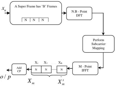
[image:5.595.53.290.316.492.2]The figure 4 shows the block diagram of Super frame technique used in SC-FDMA based systems. This technique also reduces PAPR of SC-FDMA signals.
Fig 4: Structure of the transmitter using SC-OFDM with super frame scheme
Inthis scheme B frames with N subcarriers will be combined into one super frame. It reduces the PAPR compared the normal IFDMA. The super frame with lowered PAPR will finally be divided into B OFDM frames for the transmission. The super frame technique (SF-IFDMA) is most suitable for the IFDMA systems with small number of subcarriers N, for example N ≤ 512. This scheme is very effective in reducing the PAPR in IFDMA systems, especially when N is small. It can achieve significant reduction of PAPR without requirement of and side information.
D. Companding Transform with Kalman Filter (Proposed Scheme)
A Companding using Kalman filter is an algorithm to reduce the dynamic range of a signal by increasing the amplitudes of the smaller signals . The average signal power is increased with this technique. PAPR is reduced to an extent if dynamic range is reduced. Fig. 1 shows the block diagram of OFDM system with companding scheme to reduce PAPR in OFDM systems.
a) Companding Transform
Our aim in this work involves applying u-law companding at the transmitter to reduce the PAPR of the transmitted waveform so as to reduce distortion through the transmit amplifier and allow operation closer to amplifier saturation. Values of u ranging between 0.125 and 64 were used in the study since the optimal performance was found to reside within this range of operation.
max max
|
( ) |
ln[1
]
( )
( )
[
( )]
ln[1
]
dat
c dat
x
n
u
x
x n
K u x
sign x
n
u
…… (16)
Where
max
max(
dat( ))
nx
x
n
….. (17)And where K(u) is a normalization constant such that the average power of the companded signal is equal to the average power of the uncompanded signal. A proposed approximation for K(u) is as follows:
ln(1
)
( )
u
K u
u
….. (18)However, this approximation is not highly accurate, and in practice, would lead to unnecessary degradation in the demodulation performance. To mitigate errors introduced by normalization inaccuracies, numerically-determined values of K(u) were computed and employed instead, where long-term power averages of both uncompanded and companded OFDM symbols were numerically estimated to find K(u).
To reduce the PAPR of an OFDM system a new technique based on companding with Kalman Filter is proposed in this paper. This technique gives the opportunity to keep the PAPR to an adequate level by doing the task of multiple companding which is illustrated by below given steps.
The key signal processing steps are described as follows: Step 1: Binary data is generated and modulation is performed in order to create symbols or vectors
X
m. Step 2: IFFT is performed on vectorX
m, and the output ofIFFT is represented in the form as given by equation (19).
[x(1), x(2),..., x(N)]
Tx
….. (19)
Step 3: A threshold value of PAPR based on application requirement is set for comparison i.e. for level 4 the value of the threshold is set at
4
th
PAPR
db
Step 4: Calculate
PAPR
1 and it is compared withth
PAPR
A Super Frame has ‘B’ Frames
N N N X1 X2 XB
N.B - Point DFT
Perform Subcarrier
Mapping
M - Point IFFT
N N N Add
CP
X1 X2 . . . XB
/
o p
n
x
m
X
~
s m
Step 5: If,
PAPR
1
PAPR
ththen the original signal is transmitted i.e.Transmitted signal,
t n
r( )
x n
( )
Step 6: A counter is initialized (i.e. a=0) to indicate how many times Companding is performed when,
Transmitted signal,
t n
r( )
x n
( )
Step 7: If, A Companding transform is then applied to x (n) by using Kalman Filter i.e.
1
( )
{x(n)}
x n
C
…… (20)
Step 8: Step 2 & step 4 are repeated for
x n
1( )
.Here the calculated PAPR forx n
1( )
isPAPR
2.Step 9: If
PAPR
2
PAPR
ththen,t n
r( )
x n
1( )
and a=1.Step 10: If,
PAPR
2
PAPR
th Another companding transform is applied tox n
1( )
.Step 11: This whole procedure is repeated unless
PAPR
m
PAPR
th Where m=1, 2, 3,. .a) Introduction to Kalman Filter
The Kalman filter is a mathematical tool which consists of a set of mathematical equations; these equations provide an efficient computational means in order to estimate the state of a process, in a way such that the mean of the squared error is minimized. The filter can be used to estimate past, present and even future states.In order to estimate the state
x
n of a discrete-time controlled process which is given by the linear stochastic difference equation (21) below:1 1 1
k k k k
x
Ax
Bu
w
... (21)With a measurement
z
mthat is given by Eqn. (22)k k k
z
Hx
v
…. (22) In practice H might change with each time step, but here we assume it is constant. The Kalman filter estimates a process with the help of feedback control: the filter estimates the process state at some time and then obtains feedback in the form of measurements.The equations of Kalman filter are divided into two groups viz: (1) Time Update equations and (2) Measurement Update equations. The time update equations can also be thought of as predictor equations, [16] while the measurement update equations can also be thought of as corrector equations. The equations for the time update and measurements update are given below. Kalman filter Time Update Equations as follows:
^ ^
1 1
k k k
x
A x
Bu
... (23)1
T
k k
P
AP A
Q
... (24)Kalman filter Measurement Update Equations as follows:
1T T
k k k
K
P H
HP H
R
... (25)
^ ^ ^
k k k k k
x
x
K
z
H x
... (26)
P
k
I
K H P
k
k
... (27)
4.
SIMULATION RESULTS
In this section, we present the results of computer simulations used to evaluate PAPR reduction capability. In the simulation, an OFDM system with a sub-carrier of N = 128,512 and QAM modulation was considered. We can evaluate the performance of the PAPR reduction scheme using the complementary cumulative distribution (CCDF) of the PAPR of the OFDM signal.
a. CCDF Performance
We can evaluate the performance of PAPR using the cumulative distribution of PAPR of OFDM signal. The cumulative distribution function (CDF) is one of the most regularly used parameters, which is used to measure the efficiency of and PAPR technique [15]. The CDF of the amplitude of a signal sample is given by equation (28).
.
F z
( )
1 exp( )
z
... (21) However, the complementary CDF (CCDF) is used in-stead of CDF, which helps us to measure the probability that the PAPR of a certain data block exceeds the given threshold. The CCDF of the PAPR of the data block is desired is our case to compare outputs of various reduction techniques. This is given by equation (22).P(PAPRz) 1 P PAPR( z) 1 (1 exp(z))N
[image:6.595.302.546.439.693.2]... (22)
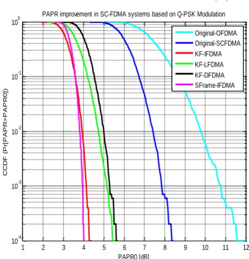
Fig. 5 PAPR PERFORMANCE OF SCFDMA USING Q-PSK AT ROLLOFF FACTOR 0.22
1 2 3 4 5 6 7 8 9 10 11 12
10-4 10-3 10-2 10-1 100
PAPR0 [dB]
C
C
D
F
(P
r[
P
A
P
R
>
P
A
P
R
0
])
PAPR improvement in SC-FDMA systems based on Q-PSK Modulation
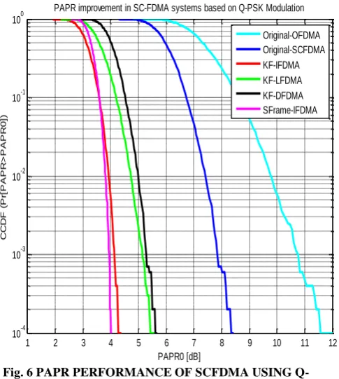
Fig. 6 PAPR PERFORMANCE OF SCFDMA USING Q-PSK AT ROLLOFF FACTOR 0.42
Fig. 7 PAPR PERFORMANCE OF SCFDMA USING Q-PSK AT ROLLOFF FACTOR 0.82
*KF-IFDMA- PAPR Reduction in IFDMA systems Using Kalman Filter
*KF-LFDMA- PAPR Reduction in LFDMA systems Using Kalman Filter
*KF-DFDMA- PAPR Reduction in DFDMA systems Using Kalman Filter
*SFrame-IFDMA- PAPR Reduction in Super Frame based IFDMA Using Kalman Filter
The simulation parameters are as follows:
No. of subcarriers: 64, 128 & 512 Modulation scheme: Q-PSK Channel: AWGN
SNR range: 0 to 20 (in dB)
Total number of Bits transmitted: 64000, 128000 & 512000 Total OFDM symbols: 1000
5.
CONCLUSION
The proposed scheme introduces an effective implementation of PAPR reduction Single Carrier- Frequency Division Multiple Access based communication systems. Simulation results have shown satisfactory PAPR performance at 10-4
CCDF level. The results are shown at different values of roll off factor using Q-PSK modulation scheme. We also analyse behaviour of system under QAM modulation scheme also. Companding based analysis provides some advantages over uncompading based analysis such as it is more immune to impulse and narrowband noises, also improves spectral efficiency and saving in transmission power. In this paper, a Kalman filter approach is used to improve the PAPR performance of OFDM system. It provides greater efficiency & good BER performance also.From the results shown in figures we observed that there is a very good improvement is found in IFDMA based systems than LFDMA based systems. We also found that Super Frame scheme gives more improved results over normal IFDMA system.
6.
ACKNOWLEDGMENTS
The authors would like to thank the anonymous reviewers for their constructive comments, which helped improve this paper.
7.
REFERENCES
[1] M. M. Rana, Md. Saiful Islam and Abbas Z. Kouzani ,” Peak to Average Power Ratio Analysis for LTE Systems,” 2010 Second International Conference on Communication Software and Networks, pp 516-520. [2] Mohamed Noune and Andrew Nix,” Frequency-Domain
Precoding for Single Carrier Frequency-DivisionMultiple Access,” IEEE Communications Magazine • June 2009, pp 68-74
[3] Elias Yaacoub and Zaher Dawy ,”A Game Theoretical Formulation for Proportional Fairness in LTE Uplink Scheduling,” IEEE Communications Society subject matter experts for publication in the WCNC 2009. [4] GILBERTO BERARDINELLI, LUIS ÁNGEL
MAESTRO RUIZ DE TEMIÑO, SIMONE
FRATTASI,” OFDMA VS. SC-FDMA:
PERFORMANCE COMPARISON IN LOCAL AREA IMT-A SCENARIOS,” IEEE Wireless Communications • October 2008, pp 64-72.
[5] F. S. Al-kamali · M. I. Dessouky · B. M. Sallam ,” Equalization and Carrier Frequency Offsets Compensation for the SC-FDMA System,” Springer Wireless Pers Commun Sep. 2011.
[6] F.S. Al-kamali · M.I. Dessouky · B.M. Sallam ,” Impact of the power amplifier on the performance of the single carrier frequency division multiple access system,” Telecommun Syst ,Springer , April 2011.
[7] Enchang SUN, Pengbo SI, Ruizhe YANG, Yanhua SUN, and Yanhua ZHANG ,” Power function companding
1 2 3 4 5 6 7 8 9 10 11 12 10-4
10-3 10-2 10-1 100
PAPR0 [dB]
C
C
D
F
(P
r[
P
A
P
R
>
P
A
P
R
0
])
PAPR improvement in SC-FDMA systems based on Q-PSK Modulation Original-OFDMA Original-SCFDMA KF-IFDMA KF-LFDMA KF-DFDMA SFrame-IFDMA
1 2 3 4 5 6 7 8 9 10 11 12 10-4
10-3 10-2 10-1 100
PAPR0 [dB]
C
C
D
F
(P
r[
P
A
P
R
>
P
A
P
R
0
])
scheme for peak-toaverage power ratio reduction of SC-FDMA signals,” 2011 10th IEEE/ACIS International Conference on Computer and Information Science, 2011. [8] Hyung G. Myung, Kyle Jung-Lin Pan, Robert Olesen, and Donald Grieco,” Peak Power Characteristics of Single Carrier FDMA MIMO Precoding System, ©2007 IEEE, pp 477-481.
[9] Meng Ma, Xiaojing Huang, Member, IEEE, Bingli Jiao, Member, IEEE, and Y. Jay Guo, Senior Member, IEEE,” Optimal Orthogonal Precoding for Power Leakage Suppression in DFT-Based Systems,” IEEE TRANSACTIONS ON COMMUNICATIONS, VOL. 59, NO. 3, MARCH 2011 pp 844-853.
[10] Gillian Huang, Andrew Nix and Simon Armour,” IMPACT OF RADIO RESOURCE ALLOCATION AND PULSE SHAPING ON PAPR OF SC-FDMA SIGNALS,” The 18th Annual IEEE International Symposium on Personal, Indoor and Mobile Radio Communications (PIMRC'07), ©2007 IEEE.
[11]Hyung G. Myung Junsung Lim and David J. Goodman,” PEAK-TO-AVERAGE POWER RATIO OF SINGLE CARRIER FDMA SIGNALS WITH PULSE SHAPING,” The 17th Annual IEEE International Symposium on Personal, Indoor and Mobile Radio Communications (PIMRC'06) 2006 IEEE.
[12]Mohamed Salah , Gamal Abdel-Fadeel, and Zaki B. Nossair ,” Peak to Average Power Ratio Reduction in Single Carrier OFDMA Systems,” ASAT-13 May 2009 pp1-12.
[13] Md. Mahmudul Hasan “A New PAPR Reduction Technique in OFDM Systems Using Linear Predictive Coding” Wireless Pers Commun DOI 10.1007/s11277-013-1387-2, Springer Science+Business Media New York 2013.
[14]Chunjiang Duanmu · Hongtao Chen ,”Reduction of the PAPR in OFDM Systems by Intelligently Applying Both PTS and SLM Algorithms,” Wireless Pers Commun, © Springer Science+Business Media New York 2013. [15] Zhongpeng Wang,” Combined DCT and Companding
for PAPR Reduction in OFDM Signals,” Journal of Signal and Information Processing, 2011 pp 100-104 [16]Mukunthan Pandurangan and Dananjayan Perumal,”