© 2016, IRJET | Impact Factor value: 4.45 | ISO 9001:2008 Certified Journal | Page 1255
FABRICATION OF MINI HOISTING DEVICE
Mr. S.N Tripathy
1, Sachin Kumar
2,
Krupasindhu Munda
3, Prassana Bauri4
Associate Professor
1, student
2, 3, 4, Dept. of Mechanical Engineering, GIET, Gunupur, Odisha, India
---***---Abstract
- In this project we tried our best to design, fabricateand to make a working model of a mini hoisting device. Generally in our workshop or construction places we need to lift our bulky loads of 15kg to 30kg manually. To make the process simpler we made a hoisting device which is a mixture of crane and hoisting device. We made it so simple that we can easily assemble and disassemble it easily at any place where there is its need. This is achieved by the provision of bolting system. Instead of welding method to join one part with other we use bolt system. The design was first made by using Auto Cad software. Then according to design parameter we cut the different cross-section and then assemble it. After assembling the engine part is attached and thus it works.
Key Words: Auto-Cad, CATIA, Hoisting, Bolt and HP.
1.INTRODUCTION
Hoisting equipment which can be portable is a large component of any mechanical shop. This can be achieved through the use of chain drives, etc. We know that all motor powered machines are expensive and need subsistence and fuel, the manually governed machines for example hoists are inexpensive and do not require much or any maintenance work.
We know that crane is a kind of hoisting device which is assembled with hoist, wire rope or cable, chain etc... It is used both to raise and put to down materials and to move them horizontally or vertically. Machine of this type is mainly used for lifting heavy or bulky things and transporting them from one other place.
Cranes are a central component in engineering industries and are related with large number of threats with its operations in workshop and also there are numerous types of hoisting machine available depending upon basic design, mechanism and working, so it is also make problem to handle these type of hoisting machinery in workshops. There are numerous types of hoisting machinery accessible in big industries which are manufactured by different manufacturer increases threat associated with it, based upon the design and technology and mechanism which make modification in safety devices, motions, braking systems of hoisting machinery which became danger to handle by regular skilled operator’s. As the machinist were shifted from one crane to another, there was a big chance of doing fault during moving the controls, which might have consequence in severe accidents, due to lack of training, guidance and education of operator’s especially during time of workload.
Movable hoists may use a hydraulic or electric technology to raise the load so that they can be shifted between two close surfaces. They are not made to transfer load from one room to another room. Many transportable hoists now use an electric servo mechanism integrating two way switch control to raise and lower the weight.
Hoisting device same as all appliances, followed the law of conservation of energy, which means that the power transfer to the load cannot cross the power given into the machine. Let us take an example, if a pulley system double the applied force, then the load moves only one and half as far as the applied force. Since energy is directly corresponding to force multiplied by distance, the resulted energy is kept roughly equal to the input energy.
The same law can operate in contradiction. In case of some difficult situation, the sum of heavy load and large height can advance small objects to large speed. Such steps can result in severe accident to nearby structures and people. Cranes can also get in continuous chain reaction; one crane can damage the other ones.
Here the main aim is to lower the cost of our device and optimum use out if it. We have used the materials which can be easily available in our workshop. We have facilitated both manual and electrical way of mechanism to lift the load and to place it in some other place where it is required.
2 LITERATURE RIVIEW
Lawrence K. Shapiro and Jay P. Shapiro stated that crane gives a cost-effective way to elevate heavy loads anywhere in a facility; therefore it is one of the most commonly used machine workshops. Old gantry cranes can be classified into fixed height and adjustable height according to the maximum load height, single girder or double girder according to the type of girder construction, and wheel mounted or rail mounted according to the way it moves. Every model has its own advantages and disadvantages with respect to the working environment, safety precautions, ease of use, maintenance, and load capacity [1].
© 2016, IRJET | Impact Factor value: 4.45 | ISO 9001:2008 Certified Journal | Page 1256 Hanafy Omar, W. Szyszkowski, Chung, Y. K., Masoud, Z. N.,
Nayfeh, A. H., Henry, R. J., and Mook D. T concentrate on the development of the crane controller [2-4,6-7].
N. Rudenko gives idea about chassis different parts are standard steel parts that are connected using welding and bolted joints to form the final chassis structure. All structure parts, welding and bolted joints are checked for shear stresses, crushing stresses and bending moment stresses using the recommended factors of safety [8].
Calculating for the preliminary design for the crane chassis structure, empirical formulae from [8] are considered such that they are chosen to be compatible with standards requirements for gantry cranes manufactures [9-11]. There are many factors to be considered while the design of the crane can be compile in the resistance due to the influence of the wind and the acceleration of the moving masses. But, these factors can be ignored considering lack of wind effect due to indoor and choosing low speeds for load hoisting and movement. Other important factor is to guarantee the operating safety as a simple mistake can lead to tragic accidents most of which are caused by relaxed load and load capacity exceeded [12].
3 THE HOISTING PARTS AND FABRICATION OF
OUR MINI HOISTING DEVICE:
3.1 Hoist motor
In our hoisting device we have used 3phase, 0.5HP Ac motor which is generally used for a house hold purposes. We use it to make the project cheaper. This type of motor is also known as induction motor or asynchronous motor. So asynchronous motor therefore does not need separate-excitation, mechanical commutation, for entire or part of the energy transferred from stator to rotor, in DC and large synchronous motors. An asynchronous motor is of 2 type squirrel-cage type or wound type.
3-phase squirrel-cage asynchronous motors are extensively used in industries because they are rough, steady, safe and cost-effective. 1-phase induction motors are used largely for lighter loads, such as household equipment like fans. In spite of conventionally used in constant-speed service asynchronous motors are greatly being used with VFD in variable-speed service. VFDs basically important energy savings scope for existing and proposed asynchronous motors in fluctuating torque centrifugal fan, compressor, pump load applications. Squirrel cage asynchronous motors are very widely used in both variable-frequency and fixed-speed variable-frequency drive appliance. Variable frequency and fluctuating voltage drives are also used in variable-speed service.
Fig.1. 0.5HP AC motor used in hoisting device
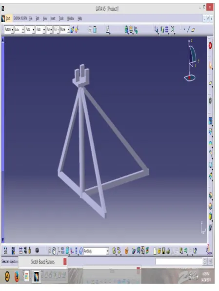
3.2 Base frame
Base frame is the main buildings block our hoisting device. It carries all the weight of the crane hand and load which is lifted by the device. The frame is like the Truss structure as we know a truss is a structure that consists of two-force members only, which are organized so that the association as a whole act as a single object. A 2-force member is a structural element where force is enforced to only two points. Although this correct definition allows the members to have all shape connected in any stable structure, trusses typically be composed of five or more triangular units manufactured with straight members whose ends are joined at joints designated as nodes. Here, reactions and external forces to those forces are treated to act only at the nodes due to which forces in the members which are either compressive or tensile. For straight members, moments (torques) are clearly excluded because, all the joints in a truss are considered as revolute.
© 2016, IRJET | Impact Factor value: 4.45 | ISO 9001:2008 Certified Journal | Page 1257
3.3 Crane boom
Boom is a part of a crane, can be called as the hand of the crane. . It is used to give facility to lift the load up to certain height so that we can place it in our desired position. Boom cranes are used to efficaciously and comfortably to lift heavy and inelegant to move objects. The crane is generally used to hoist bulky equipment and goods on construction sites, work-shops, cargo ships.
Fig.3. crane hand or boom
3.4 Wire rope
A hoisting device use wire rope, chain, fibre as its hoisting medium. Wire rope consists of number of strands twisted together like a helix. Every strand too is made of metal wires arrange together like a helix. Abrasion resistance developed with some of larger outside wires per strand. Also fatigue resistance developed with larger outside smaller wires per strand.
Concentrated wire rope is composed of number of wire strands which have passed through coiling wheels to compress and shape each of the wires to form consolidated structures or decreases diameters before wounding strands around the core. Because of benefit of the compacting process, the surface of outside wires is flattened and the meeting area between strands is increased.
We have different no. of rope falls increase in number of rope fall use in reducing the tension in the wire rope. Due to friction if no. of rope falls increases then due to friction force tension also go up in one rope fall so increases the tension by c times.
C is known as coefficient factor varies from 1.029 to 1.14.
Fig.4. Microscopic view of strands of wire
3.5 Crane Hook
Crane hooks are extremely important components and are always subjected to failure due to aggregation of large amount of stresses which can ultimately lead to its failure. Crane hooks are the hoisting unit which are generally used to upraise the heavy load in mechanical workshops and industries etc. A crane is assembled with a wire ropes or a hoist, sheaves and chains used to elevate and move heavy material. Cranes are mainly employed in construction, transport, and manufacturing industry. A crane hook is a device used for clutching and rising up the loads by means of a hoisting device or crane. It is primarily a hoisting fixture manufactured to engage link or ring of a lifting cable or chain. Therefore it must be designed and manufactured to give best performance without failure. The hooks are crucial unit and are generally subjected to failure due to aggregation of large amount of stresses, which are finally leading to failure. Due to continuous loading and unloading fatigue occurs in crane hook. If the crack is developed in the hoisting hook, leads fracture of the hook and cause to severe accident. Tensile stress, Bending stress, plastic deformation due to overburden, crippling of the hook due to wear, enormous thermal stresses are few of the other reasons of failure.
3.6 Chain drive unit
© 2016, IRJET | Impact Factor value: 4.45 | ISO 9001:2008 Certified Journal | Page 1258 proportion can be corrected according to the load to be
lifted.
Fig.5. Chain drive unit with 0.5HP motor
3.7 Rope drum
Rope drum is used for winding up of wire rope. It should have provision for guiding the wire rope while lifting and putting down the load. It also should be of high strength so that it would not bend while lifting of load.
In our project we have use a motorcycle rim as our rope drum. As it is very durable and light weight we preferred it so that maximum weight can be lifted.
Fig.6. Motorcycle rim used as Rope drum
3.8- STEPS OF FABRICATION
3.8.1 Metal cutting
We have used iron bars that are triangular, rectangular in cross section.
Dimensions are marked as per required design. We used multi point metal cutter.
Metal cutting operation is done.
Fig.7. All the cut parts
3.8.2 Welding
We need provisions for fixing of frames by using bolt for which we need flanges are welded by using arc welding.
© 2016, IRJET | Impact Factor value: 4.45 | ISO 9001:2008 Certified Journal | Page 1259
3.8.3 Assembling
[image:5.595.36.261.179.478.2]Finally the whole body structure which consist of base frame, crane boom, hoist motor, chain drive unit, wire rope and hook are assembled together.
Fig. 9. CATIA DESIGN of our Base frame
4. TABULATION AND SPECIFICATION
Sl no.
POWER
(HP)
LOAD
(Kg)
SPEED
(rpm)
TORQUE
(Nm)
1 0.5 0
1395
2.553
2 0.5 2
1185
3.006
3 0.5 4
922
3.85
4 0.5 6
698
5.103
5 0.5 8
408
8.73
6 0.5 10
203
17.54
7 0.5 12
108
32.98
5. CALCULATION
Here we are calculating the amount of torque that is required for lifting of different loading condition.
Formula used:
Power, P = (2×π×N×T)/60 Watt Eq. (1)
P = 0.5 HP = 0.5×745.6998 watt Eq. (2)
= 372.849 watt
T1 = (60 ×372.849)⁄(2×3.14×1395)
= 2.553 N.m
© 2016, IRJET | Impact Factor value: 4.45 | ISO 9001:2008 Certified Journal | Page 1260
6 GRAPH
CHART 1: Speed vs. Load
CHART 2: Speed vs. Torque
7. Result
For the same power input when we vary the load in increasing order the torque for each additional weight increases.
8. CONCLUSION
The aim of our project was to fabricate a working model of mini hoisting crane type device which is capable to lift a load of 10 kg or more. And hence we successfully achieved our target. Also we are successful in making the motion of vertical crane boom to rotate〖360〗^°. We are sure that it can lift more than 10Kg.
REFRENCE
[1] Lawrence K. Shapiro, Jay P. Shapiro, "Cranes and Derricks", McGraw Hill Inc., 4th ed., 2010.
[2] Hanafy Omar, "Control of Gantry and Tower Cranes", PhD thesis, Faculty of the Virginia Polytechnic Institute and State University, 2003.
[3] W. O. Connor and H. Habibi, “Gantry crane control of a doublependulum, distributed-mass load, using mechanical wave concept,” Mechanical Sciences, vol. 4, pp. 251–261, 2013.
[4] S. Woods and W. Szyszkowski, "Optimal Manoeuvres of Underactuated Linear Mechanical Systems: The Case of Controlling Gantry Crane Operations", Journal of Applied Mathematics, Article ID 283565, Volume 2014, 16 pages, http://dx.doi.org/10.1155/283565/2014.