© 2016, IRJET ISO 9001:2008 Certified Journal Page 1103
Bit Error Rate Analysis of OFDM
Nishu Baliyan
1, Manish Verma
21
M.Tech Scholar, Digital Communication Sobhasaria Engineering College (SEC), Sikar (Rajasthan Technical University) (RTU), Rajasthan India
2Assistant Professor, Department of Electronics and Communication Engineering
Sobhasaria Engineering College (SEC), Sikar (Rajasthan Technical University) (RTU), Rajasthan India
---***---Abstract -
Orthogonal Frequency Division Multiplexing or OFDM is a modulation format that is being used for many of the latest wireless and telecommunications standards. OFDM has been adopted in the Wi-Fi arena where the standards like 802.11a, 802.11n, 802.11ac and more. It has also been chosen for the cellular telecommunications standard LTE / LTE-A, and in addition to this it has been adopted by other standards such as WiMAX and many more. The paper focuses on The MATLAB simulation of Orthogonality of multiple input multiple output (MIMO) signals and bite error rate (BER) with MIMO transmitter and receiver.Key Words: Long Term Evaluation (LTE), Bit Error Rate
(BER), Orthogonal Frequency Division Multiplexing (OFDM),
1. INTRODUCTION
OFDM is a bandwidth efficient signaling scheme for digital communications that was first proposed by Chang. The main difference between frequency division multiplexing (FDM) and OFDM is that in OFDM the spectrum of the individual carriers mutually overlap, giving therefore an optimum spectrum efficiency (asymptotically Q b/Hz for modulation of each carrier). OFDM carriers exhibit the property of orthogonality on a symbol interval if synthesized such that they are spaced in frequency exactly at the reciprocal of the symbol interval. There are two deleterious effects caused by frequency offset, out of which one is the reduction of signal amplitude in the output of the filters matched to each of the carriers and the second is introduction of IC1 from the other carriers which are now no longer orthogonal to the filter. Because, in OFDM, the carriers are inherently closely spaced in frequency compared to the channel bandwidth requirement, the tolerable frequency offset becomes very small fraction of the channel bandwidth requirement. Maintaining sufficient open loop frequency accuracy can become difficult with links, such as satellite links with multiple frequency channels
estimations and translations or, as mentioned previously, in mobile digital links that may also introduce significant Doppler shift. Orthogonal frequency division multiplexing has also been adopted for a number of broadcast standards from DAB Digital Radio to the Digital Video Broadcast standards, DVB. It has also been adopted for other broadcast systems as well including Digital Radio Mondiale used for the long medium and short wave bands. Although OFDM, orthogonal frequency division multiplexing is more complicated than earlier forms of signal format, it provides some distinct advantages in terms of data transmission, especially where high data rates are needed along with relatively wide bandwidths. OFDM is a form of multicarrier modulation. An OFDM signal consists of a number of closely spaced modulated carriers. When modulation of any form - voice, data, etc. is applied to a carrier, then sidebands spread out either side. It is necessary for a receiver to be able to receive the whole signal to be able to successfully demodulate the data. As a result when signals are transmitted close to one another they must be spaced so that the receiver can separate them using a filter and there must be a guard band between them. This is not the case with OFDM. Although the sidebands from each carrier overlap, they can still be received without the interference that might be expected because they are orthogonal to each another. This is achieved by having the carrier spacing equal to the reciprocal of the
symbol period. OFDM is very effective for
© 2016, IRJET ISO 9001:2008 Certified Journal Page 1104 (as seen by the individual subcarriers). Flat fading is
easier to combat (compared to frequency selective fading) by employing simple error correction and equalization schemes.
2. MIMO OFDM
Multiple transmit and receive antennas can be used to form multiple-input multiple-output (MIMO) channels to increase the capacity by a factor of the minimum number of transmit and receive antennas. In this paper, orthogonal frequency division multiplexing (OFDM) for MIMO channels (MIMO-OFDM) is considered for wide band transmission to mitigate inter symbol interference and enhance system capacity. MIMO (Multiple Input Multiple Output) is a diversity technique and one of the most recent contributions in the communication field. MIMO improves the received signal quality and increase the data communication speed by using various digital processing technique to combine the signal via various wireless path i.e. through multiple transmit and receive antennas. This type of configuration is quite complex and consume lots of power. Therefore some schemes have been proposed to reduce the system complexity. In wireless communication there occurs frequency selective fading in channel, this results in the intersymbol interference that can degrade the communication quality. So to overcome with this problem, OFDM system is used.
A MIMO-OFDM system with four transmit and receive antennas is shown in Fig.1.Though the figure shows MIMO-OFDM with four transmit antennas, the techniques developed can be directly applied to OFDM systems with any number of transmit antennas. At
time, n each of two data blocks,{ } for
i= 1 and 2, is transformed into two different signals, for } for i = 1 and 2, respectively, through two space time encoders. The OFDM signal for the transmit antenna is modulated by [n,k] at kth tone of the nth OFDM block.
Fig.1 OFDM MIMO system
From the figure, the received signal at each receive antenna is the super position off our distorted transmitted signals, which can be expressed as
for denotes the additive complex
Gaussian noise at the jth receive antenna, and is assumed to be zero-mean with variance and uncorrelated for different n’s,k ’s,or j’s.
denotes the channel frequency response for the kth tone
at time n, corresponding to the ith transmit and the jth
receive antenna. The input–outpu trelation for OFDM can be also expressed in vector form as
Where
© 2016, IRJET ISO 9001:2008 Certified Journal Page 1105
3. MODEL OF MIMO OFDM
MIMO system consists of three components, mainly transmitter, channel and receiver. Transmitter sends a multiple data such as x1, x2, x3… xN say xi from different
transmit antenna and signal is received by each receive antenna (r1, r2, r3….rN say rj) simultaneously. The
relation between transmit data and receive data is given by
r1= h11 x1 + h12 x2+…+ h1N x N,
r2= h21 x1 + h22 x2+…+ h2N x N,
…
[image:3.595.42.283.239.418.2]rN = hN1 x1 + hN2 x2+...+ hNN x N.
Fig. 2 MIMO System Model.
The MIMO signal model is described as
r = Hx+n, (2)
where r is Nr*1 received signal vector, H is Nr*Nt the
channel matrix, x is Nt*1 transmitted vector and n is
Nr*1 Gaussian noise vector. With Nt inputs and Nr
outputs the channel can be expressed as Nr*Nt channel
matrix H. By showing the channel in a matrix form, we can fully recover the transmitted data. The channel matrix can be represented as
Where hij is the attenuation and phase shift between
the j transmitter and i receiver. It is assumed the MIMO channel behaves in the quasi static manner [14].
4. CAPACITY Of MIMO OFDM channel
Capacity is maximum possible information that can be transmitted with available bandwidth and transmitted power [15]. In single antenna SISO having bandwidth
B, transmitted power P, noise spectrum No and channel assumed to be white Gaussian, then the capacity of a system is given by Shannon’s capacity formula
C= B log2( 1 + SNR)
When multiple antennas are used, channel faces multiple input and output, and its capacity is determined by extended Shannon’s capacity. Antenna with Nt input from transmitter and Nr output in a
receiver channel is expressed as Nr * Nt matrix of
channel H The capacity of a MIMO channel can be estimated by the following equation
Where H is Nr x Nt channel matrix, Rx is
covariance of input signal x, HH is transpose conjugate
of H matrix and is the variance of the uncorrelated and Gaussian noise [16]. Since this equation is obtained by large theoretical calculations, but practically it has never been achieved yet. To achieve more precise results linear transformation at both transmitter and receiver can be performed by converting MIMO channel (Nr, Nt) to a SISO sub channel min (Nr, Nt).
According to singular value decomposition (SVD) every matrix can be decomposed. Suppose the channel
matrix H transformation is given by H = UDVH, Where
the matrix U is Nr x Nr matrix, V is Nc x Nc matrix and D
is non-negative diagonal matrix of Nr x Nt. Therefore
capacity of N SISO subchannels is sum of individual capacity and results the total MIMO capacity. MIMO capacity varies for different numbers of transmit antennas and receiver antennas. The MATLAB program can calculate the theortical MIMO capacity of 200 random MIMO cxhannels of different sizes at an SNR of 3 dB. We consider the case a transmitter that does not have the MIMO channel knowledge . Hence, each transmit antena is allocated the same signal power Additionally , the channel noises are assumed to be indepndent additive white Gaussian with variance . The entries in the MIMO channel matrix H are randomly generated from Gaussian distribution of zero mean and unit variance . Because the channels are random for M transmit antennas and N receive antennas, the MIMO capacity per ytransmission is
© 2016, IRJET ISO 9001:2008 Certified Journal Page 1106
random. From the 200 channels, each N x M MIMO configuration should generate 200 different capacity values.
5. SIMULATION RESULTS
Communications System Toolbox™ provides
algorithms and tools for the design, simulation, and analysis of communications systems. These capabilities
are provided as MATLAB® functions, MATLAB System
objects™, and Simulink® blocks. The system toolbox
includes algorithms for source coding, channel coding,
interleaving, modulation, equalization,
synchronization, and channel modeling. Tools are provided for bit error rate analysis, generating eye and constellation diagrams, and visualizing channel characteristics. The system toolbox also provides adaptive algorithms that let you model dynamic communications systems that use OFDM, OFDMA, and MIMO techniques.
6. Conclusions
We have also implemented the OFDM for MIMO system. The BER is calculated with respect to single input single output (1 x1) system, single transmitter two receivers (1 x 2), single transmitter and four receivers (1 x 4). The BER analysis and MATLAB simulation expresses that the value of BER is decreasing as the number of receiver antennas are increasing. For the perfect MIMO OFDM system the BER should be decreased and channel capacity should be increased. The orthogonal nature of the ODDM signal is also simulated. The MIMO OFDM system are the boon for 4G and next generation of the wireless communication systems.
REFERENCES
[1] A. V. Oppenheim and R. W. Schafer, Discrete-Time Signal Processing. Englewood Cliffs, NJ: Prentice-Hall, 1999.
[2] Asymmetric Digital Subscriber Line Transceivers 2 (ADSL2), ITU-T Standard G.992.3, Jan. 2005.
[3] A. Cortes, I. Velez, and J. F. Sevillano, “Radix rk FFTs: Matricial representation and SDC/SDF pipeline implementation,” IEEE Trans. Signal Process., vol. 57, no. 7, pp. 2824–2839, Jul. 2009.
[4] A. Raghunathan , S. Dey, N. K. Jha, “High-level macro-modeling and estimation techniques for switching activity and power consumption”, Very Large Scale Integration (VLSI) Systems, IEEE Transactions on, Vol. 11, Issue 4, Aug. 2003 Page(s):538 – 557.
[5] B. M. Baas, “A low-power, high-performance, 1024-point FFT processor,” IEEE J. Solid-State Circuits, vol. 34, no. 3, pp. 380–387, Mar. 1999.
[6] B. G. Jo and M. H. Sunwoo, “New continuous-flow mixed-radix (CFMR) FFT processor using novel in-place strategy,” IEEE Trans. Circuits Syst. I, Reg. Papers, vol. 52, no. 5, pp. 911–919, May 2005.
[7] C.-L. Hung, S.-S. Long, and M.-T. Shiue, “A low power and variable length FFT processor design for flexible MIMO OFDM systems,” in Proc. IEEE Int. Symp. Circuits Syst., May 2009, pp. 705–708
[8] E. E. Swartzlander, W. K. W. Young, and S. J. Joseph, “A radix 4 delay commutator for fast Fourier transform processor implementation,” IEEE J. Solid-State Circuits, vol. 19, no. 5, pp. 702–709, Oct. 1984.
[9] S Salivahanan, “C Gnanapriya “Didital Signal Processing” Second Edition Tata McGraw Hill Education Private Limited , New Delhi. 2011.
[10] M. Karunaratne, C. Ranasinghe, A. Sagahyroon, “A dynamic switching activity generation technique for power analysis of electronic circuits,” Circuit and
Systems, 2005, 48thMid west Symposium on , Page(s)
1884-1887 Vol.2, 7-10 Aug. 2005.
[11] Y.-T. Lin, P.-Y. Tsai, and T.-D. Chiueh, “Low-power variable-length fast Fourier transform processor,” IEE Proc. Comput. Digital Tech., vol. 152, no. 4, pp. 499– 506, Jul. 2005.
© 2016, IRJET ISO 9001:2008 Certified Journal Page 1107
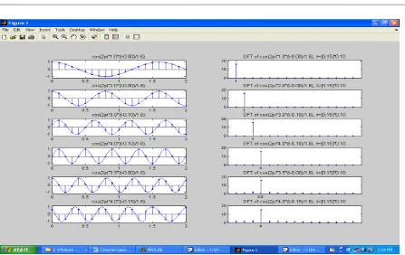
Fig. 3 Orthogonality of MIMO signals
[image:5.595.78.522.391.661.2]© 2016, IRJET ISO 9001:2008 Certified Journal Page 1108
BIOGRAPHIES
Nishu is presently pursuing M.Tech in Digital
Communication from SobhaSaria Engineering College (rajasthan). She did her B tech in Electrical and Electronics Engineering from BIT,Meerut(UPTU)
Manish Verma is presently working as an Assistant Professor in the Department of Electronics and
Communication Engineering in Sobhasaria Group of Institutions, Sikar (Raj.). He is pursuing his PhD from ISM Dhanbad in Electronics & Communication