© 2016, IRJET | Impact Factor value: 4.45 | ISO 9001:2008 Certified Journal
| Page 812
A COMPLEXITY REDUCTION TECHNIQUE FOR MULTI HOP RELAY
NETWORK WITH OUT SIGNAL INFORMATION
A.VENKATA HANUMALEELA
1, M.NAGA MANI
21
A.V.H.LEELA, PG Student, Department of Electronics &Communication Engineering, SRKIT, Vijayawada, India
2M.NAGA MANI, Assistant professor, Department of Electronics &Communication Engineering, SRKIT, Vijayawada,
India
---***---Abstract
- Improved Differential distributed space-timecoding (I-DDSTC) has been consider to improve both diversity and data rate in the absence of channel (signal) information [CSI]. This paper proposes a new differential encoding and decoding process for D-DSTC systems with two relays. The proposed method is robust against synchronization errors and does not require any channel information at the destination. Simulation results shows less complexity for various synchronization errors without CSI at receiver.
Key Words
:
Differential Distributed space time coding, diversity, differential encoding and decoding, synchronization errors, OFDM, relay networks.1. INTRODUCTION
Cooperative communication techniques are used in a network can listen to a source during its transmission phase, they are able to re-broadcast the received data to the destination in another phase. Therefore, the overall diversity and performance of a network would benefit cooperatively by multiple users. Depending on the protocol, relays are used to process and re-transmit the received signal to the destination.
On the other hand, due to the dispensed nature of relay networks, the received signals from relays at the destination are not always aligned in the symbol level. They are known as synchronization errors between relays, causes inter symbol interference (ISI).
1.1
DSTC Network
A differential encoding and decoding process is designed to contest synchronization error when neither CSI nor synchronization delay are available at the destination. We consider the case that a source communicates with a destination via two relays and the received signals from the two relays may not be aligned. All channels are assumed to be Rayleigh flat-fading and slowly changing over time. Differential encoding and decoding are
combined with an OFDM approach to circumvent both channel estimation and the ISI. At the source, differential encoding and the Inverse Discrete Fourier Transform (IDFT) are employed. At the relays, essential configuration and a protecting guard are applied as will be detailed later. At the destination, the Discrete Fourier Transform (DFT) and differential decoding are utilized to obtain a symbol-by-symbol decoding with low complexity. The proposed method does not require any CSI or the amount of synchronization error and provides significant performance improvement compared to cases with symbol misalignment.In DSTC networks, the relays cooperate to combine the received symbols by multiplying them with a fixed or variable factor and forward the resulting signals to the destination. The cooperation is such that a space-time code is effectively constructed at the destination. Coherent detection of transmitted symbols can be achieved by providing the instantaneous channel state information (CSI) of all transmission links at the destination. Although this requirement can be accomplished by sending pilot (training) signals and using channel estimation techniques.
1.2SYSTEM MODEL
© 2016, IRJET | Impact Factor value: 4.45 | ISO 9001:2008 Certified Journal
| Page 813
Fig.1. Cooperative network under consideration, Source communicates with Destination through two relays.
In the conventional DDSTC system, information bits are converted to symbols from constellation set
v
(such as PSK, QAM) at Source. Let us assume that two symbols1
,
2v v
v
are going to be sent from Source to Destination. The transmission process is divided into two phases and sending two symbols from Source to Destination in two phases is referred to as “one transmission block”, indexed byk
Z
. First, symbols are encoded to a Unitary space-time coding (USTC) matrix as 1 *2
*
2 2
2 1
1 2
1
(1)
k
v
v
V
v
v
v
v
Fig2. Received signals from Relays 1 and 2 at Destination after the matched filter using a raised-cosine pulse-shape with roll-off factor
0.9
.The received signals at Destination at block-index (k) can be written as
k k k k-1 k
y1 =g x1 11 +g20 21x +g21 22x + n1
k k k k k
y2 =g x1 12 +g20 22x +g21 21x + n2 2
Where
g20=p τ g ,g
2 21=p T -τ g ,
S 2and
k
nj CN 0,N0 , j=1,2 are the noise element at
Destination. Thus, the effect of synchronization error is collected into quantities
g
20andg
21.Depending on the number of side-lobes of the pulse-shape filter, more terms may appear in (2). In our model, the small contributions of the side-lobes ofp t
are neglected .if the information is not available (system under consideration), one can treat the ISI as noise. In this case, assuming that channel coefficients are constant during two consecutive blocks, the data symbols can be conventionally decoded as
k k k-1
v , v = arg min y1 2 -V y 3
v
1.3REVIEW OF PREVIOUS METHOD
In this section consider a GSM system with ordered block MMSE detector. The MIMO channel is assumed to be of quasi-static frequency flat fading, and hence can be represented by a
N
rXNtchannel matrix H. Consequently,the received signal y can be described as y = Hx + w, where x denotes the transmitted symbol vector, and w denotes the zero-mean circularly-symmetric complex Gaussian random noise vector with covariance matrix .
In GSM system, only
N
ptransmit antennas are activated ateach time instance. Consequently, there are t p
N N
C
possibleTACs. Among these TACs, N = log (C2 NtNp)
2
TACs are chosen to conveylog N
2 bits of information. Since only antennas are active, and are assumed to be drawn i.i.d. from a M-ary constellation set. We first denote the channel matrix associated to the TAC as H = B,c]I [ , where B and c areformed by the first Np – 1 column vectors and the last column vector ofHIrespectively. By using the property of
projection matrices, we have
I [ ] B
H B,c B ( P )c I-P =I-P =P
and
P,
wherePB
and
P(I-PB)cdenote projection matrices associated to the subspaces spanned by the columns of B and(I-P )c
Brespectively. It follows that for any two arbitrary vectors f
r r
N ×1 N ×1
C
and g C
, one can compute.
I B B
I
H H H H
H [B,c] H (I-P )C
H H H 2
H H B B
H [B,c] 2 H
B
f P g=f P
g=f P g+f P
g
for special case f=g=y then we obtain
y P y+|c y-c P y|
y P y=y P
y=
© 2016, IRJET | Impact Factor value: 4.45 | ISO 9001:2008 Certified Journal
| Page 814
With the above procedure, we can write the explicitexpression of I
H H
y P y for any Np - 2 in terms of inner
products among the columnsHI and y. Here we provide
the explicit expression for the Np = 3 as an example. From the above discussion, it is clear that the computation Of
I
j H H
u =y P y
can always be decomposed into some basicarithmetic operations of inner products between the columns of
H
Iand the data vector y, and also the innerproducts between the columns of
H
I . Let the weightingfactors be sorted as
1 2 N
m m m
u _u
_. . ._u
. Since there areonly finitely many (more precisely) possible channel vectors, it is expected that when we compute
u
mjfor somerelatively large j, many of the required inner product terms may have already been computed when computing
1 2 (j-1)
m m m
u _u _. . ._u . This motivates the development of
the previous CECML computation algorithm in which the redundant computation of these inner product terms is avoided.
A summary of the proposed CECML ordering algorithm for the case of Np = 3 is described as in Table I.
TABLE1:summary of CECML algorithm
N X Nr
N t
input:TAC sets {I } and channel matrix H C
j j=1 Î
N output:weighting factors {u } =1
j j
N X Nt t N X Nt t N X1t
1.set Γ =0 ,Φ =0 ,γ =0
hh hh hy
2.for l=1 to N dot
2 H
3. [Γ ] =||h || , [Φ ] =1,[γ ] =h y hh l,l l hh l,l hy l l 4.end for
5.for j=1 to N do 6.if [Φ ] ==0 then
hh j j 2, 1
H
7.[Γ ] ==h h ,[Φ ] =1 hh j j j j hh j j
2, 1 2 1 2, 1
*
8.[Γ ] ==[Γ ] ,[Φ ] =1
hh j j hh j j hh j j
1, 2 2, 1 1, 2
9.end if
10.if [Φ ] ==0 then hh j j3, 1
H
11.[Γ ] ==h h ,[Φ ] =1 hh j j j j hh j j
3, 1 3 1 3, 1
* 12.[Γ ] ==[Γ ]
hh j j hh j j
1, 3 3, 1
,[Φ ] =1 hh j j
1, 3 13.end if
14.if [Φ ] ==0 then hh j j
3, 2 H
15.[Γ ] ==h h ,[Φ ] =1 hh j j j j hh j j
3, 2 3 2 3, 2
*
16.[Γ ] ==[Γ ] ,[Φ ] =1 hh j j hh j j hh j j
2, 3 3, 2 2, 3
17.end if
H H
18.compute u using y P[t1,t2,t3]y=y P[t1,t2]y+num/den with following q
j uantites
H H H
t y=[γ ] ,t y=[γ ] ,t y=[γ ] ,
1 hy j 2 hy j 3 hy j
1 2 3
2 2
||t || =[Γ ] , ||t || =[Γ ]
1 hh j j 2 hh j j
1, 1 2, 2
2 ||t || =[Γ ]
3 hh j j 3, 3
H H *
t t =(t t ) =[Γ ] 1 2 1 2 hh j j
1, 2
H H *
t t =(t t ) =[Γ ] 1 3 1 3 hh j j
1, 3
H H *
t t =(t t ) =[Γ ] 2 3 2 3 hh j j
2, 3 19.end for
The algorithm first initializes the elements in
hh h,h hy
Γ ,
, and γ
to be all zeros. The (l,m)th element ofhh
Γ
will used to store the value of Hl m
h h
after it has beencomputed. The (l,m)th element of
h,h
is set to 1 if[Γ ]
hh l,mhas been computed and then stored, while lth element of
y
H
h l
© 2016, IRJET | Impact Factor value: 4.45 | ISO 9001:2008 Certified Journal
| Page 815
2. PROPOSED METHOD
In this section, we propose a method for combating the synchronization error in the above system. The method combines differential encoding and decoding with an OFDM approach and is referred to as Differential OFDM (D-OFDM) DSTC. To establish the notation, first a brief review of OFDM systems is provided.
2.1 OFDM System
Frequency selective channels are usually modeled with finite impulse response (FIR) filters in the base-band. The channel output is the convolution of the channel impulse response and input sequence which leads to ISI. OFDM is a low complexity approach to deal with the ISI encountered in frequency-selective channels as explained in the following. Let
x n
,n=0,...,N-1
represent the datasymbols of length N and
h ,...,h0 L-1
represent the discrete time channel of length L. The N-point IDFT defineas
N-1
n=0
X m =IDFT x n =1 N
x n exp j2πnm N is applied to obtain sequence. Let us assume that the additive noise is zero. The channel output sequence, after
Fig4. Encoding process at Source
Removing the first L received symbols, then we get
Y m =h Ä X m ,1 m=0,...,N-1.From
N-1
y n =DFT Y m =1 N Y m exp -j2πmn N m=0
is applied.
Using OFDM, the ISI is removed and the L-tap frequency-selective channel is converted to N parallel flat-fading channels.
2.2Differential OFDM DSTC
Using Eq(2), the effect of synchronization error is modeled by a frequency-selective channel with two taps and the OFDM method is utilized to remove the ISI. Similar to the conventional method, a two-phase transmission process is employed. However, instead of two symbols, a sequence of symbols will be transmitted during each phase. In Phase I, Source encodes data information as depicted in Fig. 4 and transmits 2N symbols to the relays. Then, the relays apply a special configuration, append 2L symbols and transmit 2(N+L) symbols to Destination in Phase II. Finally, Destination removes the symbols 2L and decodes the 2N
symbols. Transmission of
2
N
symbols from Source to Destination in two phases is referred to as “one block transmission”, indexed byk
Z
. The two sequences are then encoded to USTC matrices based on (1) to differentially encoded asObtain
V n ,
n=1,...,N
. Next, matrices
V n
are
k k k-1 1
2
0 t
s n
s n
= V n
s n
=
s n
s n
= 1
0 ,
n=0 ,...., N-1,
9
for simplicity of notations, the block-index
k
is omitted.Then, the N-point IDFT is applied to
s n ,
1
s n
2
then
S m =IDFT s n
1
1
andS m =IDFT s n ,
2
2
m=0,..., N-1
. The obtained sequencesS m
1
andS m
2
are then transmitted consecutively from Source to the relays over two sub-blocks, in Phase I. The received signals at the relays for
m=0,..., N-1
are expressed as
ij 0 i j ij
R m = 2P q S m + Z m ,
i,j=1,2
10
Where Zij
m CN 0,N
0 are the noise elements atRelay
i
and sub-blockj
. The received signals at Relays 1 and 2 form
0,...,
N
1
are configured as
1j 1j
o *
21 22
o *
22 21
X m = A R m , j=1,2,
X m = -A R m ,
X m = A R m , 11
Where A is the amplification factor and
R
2j
m
is thecircular time-reversal[15] of R2j
m defined as
o 2j
2j
2j
R 0 , m=0
R m = 12
R N-m , otherwise.
Before transmission, the last
L
symbols of sequences
Xij m ,i, j=1,2
are appended to their beginnings as the cyclic prefix to obtain
Xij N-L ,..., Xij N-1 ,..., Xij N-1
With length N+L. Here, L is the cyclic prefix length
determined based on the amount of delay between the received signals from both relays and will be discussed shortly.
In Phase II, Relay 1 transmits sequences
X11
m
and
© 2016, IRJET | Impact Factor value: 4.45 | ISO 9001:2008 Certified Journal
| Page 816
X22 m
, for m=L,...,.,...,N-1, during two consecutivesub blocks or 2(N+L) symbols, to Destination.
At Destination, without loss of generality, let us assume that the received signal from Relay 2 is
dT +τS
seconds delayed with respect to that of Relay 1, where d is an integer number and
0
T
S . Thus, to avoid ISI, the cyclic-prefix length is determined as L>d. If the delay, as shown in Fig. 2, is less than one symbol duration, L=1is enough. In practice the relays do not need to know the delay and, based on the propagation environment, the maximum value of d in the network can be estimated and used to determine the cyclic prefix length.In this case, the received signals during two sub-blocks, after removing the first L symbols, can be expressed as
1 1 11 20 21 21 21 1
1 11 2 21 1
Y m = g X m + g X m-d + g X m-1-d + W m
=g X m + g m ÄX m-d + W m , m=0,..., N-1 13
2 1 12 20 22 21 22 2
1 12 2 22 2
Y m = g X m + g X m-d + g X m-1-d + W m
=g X m + g m ÄX m-d + W m , m=0,..., N-1 14
Where g2
m = 1 g21δ m-l
l=0 .By substituting (11) and (10) into the above equations, one obtains, for
m
0,...,
N
1
o *
1 0 1 1 2 2
o *
1 11 2 22 1
Y m =A 2P h S m -h m Ä S m-d
+A g Z m -g m Ä Z m-d +W m 15
o *
2 0 1 2 2 1
o *
1 12 2 21 2
Y m =A 2P h S m +h m Ä S m-d
+A g Z m +g m Ä Z m-d +W m 16
where sequences So
mj and
o
Z2j m are the circular
time reversal sequencesSj
m andZ2j
m , respectively.By taking the N-point DFT ofY m1
, Y2
m sequencesand the properties of circular time-reversal1 sequences, forn=0,...,N-1, one derives
*
y1 n =A 2P0 h s1 1 n -H2 n s2 n +w1 n ,
*
y2 n =A 2P0 h s1 2 n +H2 n s1 n +w2 n , 17
with * H2 n = q G2 2 n ,
-j2πd N G2 n = g20+g21e ,
*
w1 n =A g z1 11 n -G2 n z22 n +w1 n , *
w2 n =A g z1 12 n +G2 n z21 n +w2 n , z11 n =DFT Z11 m , z22 n =DFT Z22 m , z12 n =DFT Z12 m , z21 n =DFT Z21 m ,
w1 n =DFT W1 m , w2 n =DFT W2 m . 18
Clearly,zij
n CN 0,N
0 and wj
n CN 0,N
0 for,
1, 2
i j
.The received signals for the block-index (k),
k
ty n = y n
1 y2 n
,in the matrix form, can beexpressed as
*
1
1 2 1
0 *
2
2 1 2
2 19
k s n s n h w n
y n A P
H n
s n s n w n
It is pointed out that, for given
g
1,g
2the equivalent noise
t
2
w1 n w2 n CN 0,σ N I ,2
where
2 2
2 2
σ n =N0
1+A
g1 + g2 c n
, 20
-j2πn N2
c n = p τ +p T -τ eS . 21
Fig5. Average received SNR vs.
n
and
Also, the received SNR per symbol, for given
g
1,g
2 can
2 2 2
0 1 2 2 2 2
0 1 2
A P g + g c n
γ n,τ = 22
N 1+A g + g c n
With raised-cosine filter,
p τ =1
andp T -τ =0
S
for0
and hencec n =1
. Thus, the noise variance and© 2016, IRJET | Impact Factor value: 4.45 | ISO 9001:2008 Certified Journal
| Page 817
that of the conventional D-DSTC for
0
. However, for0
the average received SNR is a function of
andn
. To see this dependency, γ τ,n
is plotted versusn
and
inFig.5,when
N=64 , L=1,
0= P
N 25dB,P =0 P2,
r P
P = ,
4 and for simplicity
2 2
1 2
1
g
g
. As can be seen,
,
n
is symmetric around its minimum atn
N
2 1
Also, overall,
,
n
decreases with increasing
and reaches its minimum value at
0.5
T
S. This phenomena yields the same average BER for symmetric values of
around0.5
T
S, as will be seen in the simulation results.
Ù Ù k k k-1
1 2
v
v n , v n =arg min y n -V n y n , 23
decode 2N data symbols. Because of the orthogonality of V[n], symbols v1
n ,v2
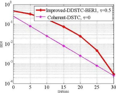
n are decoded independently, without any knowledge of CSI or delay. It is easy to see that, due to the structure of Eq.(19), the desired diversity of two is achieved in this system.2.3 SIMULATION RESULTS
Fig6.Simulation for BER of D-OFDM DSTC (proposed method,
N
64 ,
L
1,
)and coherent DSTC using BPSK for delays.Fig7 Simulation for BER of D-OFDM DSTC (proposed method,
N
64 ,
L
1,
), D-DSTC , and using BPSK forvarious values of delays
.
Fig 6: Simulation for BER of D-OFDM DSTC (proposed method,
N=64 ,
L=1,
), D-DSTC, and coherent DST usingBPSK for various values of delays.
As shown in the figure, the performance of the conventional D-DSTC system is severely degraded and an error floor appears in the BER curves. On the other hand, the proposed method is able to deliver the desired performance for all values of the delays. As explained in Section III, the BER curves are symmetric around
0.5
T
S
.3. CONCLUSIONS
[image:6.595.43.237.439.594.2]© 2016, IRJET | Impact Factor value: 4.45 | ISO 9001:2008 Certified Journal
| Page 818
channel estimation and deal with synchronization error. Itwas shown through simulations that the method works well for various synchronization error values.
REFERENCES
[1] An Improved Ordered-Block MMSE Detector for Generalized Spatial Modulation article in IEEE
communications letters, may 2015
[2] J. N. Laneman, D. N. C. Tse, and G. W. Wornell, “Cooperative diversity in wireless networks: Efficient protocols and outage behavior,” vol. 50, no. 12, pp. 3062 – 3080, Dec. 2004.
[3] J. N. Laneman and G. W. Wornell, “Distributed space-time-coded protocols for exploiting cooperative diversity in wireless networks,” vol. 49, no. 10, pp. 2415 – 2425, Oct. 2003.
[4] Y. Jing and H. Jafarkhani, “Using orthogonal and quasi-orthogonal designs in wireless relay networks,” IEEE Trans. Inform. Theory, vol. 53, no. 11, pp. 4106–4118, Nov. 2007.
[5] Y. Jing and B. Hassibi, “Distributed space-time coding in wireless relay networks,” IEEE Trans. Commun., vol. 5, no. 12, pp. 3524 –3536, Dec. 2006.
[6] P. A. Anghel and M. Kaveh, “On the performance of distributed spacetime coding systems with one and two non-regenerative relays,” IEEE Trans. on Wireless Commun., vol. 5, no. 3, pp. 682 – 692, Mar. 2006.
[7] Y. Jing and H. Jafarkhani, “Distributed differential space-time coding for wireless relay networks,” IEEE Trans. Commun., vol. 56, no. 7, pp. 1092 –1100, Jul. 2008. [8] G. Wang, Y. Zhang, and M. Amin, “Differential distributed spacetime modulation for cooperative networks,” IEEE Trans. on Wireless Commun., vol. 5, no. 11, pp. 3097 –3108, Nov. 2006.
[9] T. Wang, Y. Yao, and G. B. Giannakis, “Non-coherent distributed space time processing for multiuser cooperative transmissions,” IEEE Trans. on Wireless Commun., vol. 5, no. 12, pp. 3339 –3343, Dec. 2006.
[10] S. Wei, D. L. Goeckel, and M. C. Valenti, “Asynchronous cooperative diversity,” IEEE Trans. on Wireless Commun., vol. 5, no. 6, pp. 1547– 1557, Jun. 2006.
[11] Y. Mei, Y. Hua, A. Swami, and B. Daneshrad, “Combating synchronization errors in cooperative relays,” in IEEE Proceedings. Int. Conf. on Acoust., Speech and Signal Proc.,(ICASSP), Mar. 2005, vol. 3, pp. 369–372 Vol. 3.
[12] S. Barghi and H. Jafarkhani, “Exploiting asynchronous amplify-and forward relays to enhance the performance of IEEE 802.11 networks,” IEEE/ACM Trans. Network., vol. PP, no. 99, pp. 1–12, 2014, to appear.
[13] F. C. Zheng, A. G. Burr, and S. Olafsson, “Pic detector for distributed space-time block coding under imperfect synchronization,” Electronics Letters, vol. 43, no. 10, pp. 580–581, May 2007.
[14] Z. Li and X. Xia, “A simple Alamouti space-time transmission scheme for asynchronous cooperative systems,” IEEE Signal Process. Letters, vol. 14, no. 11, pp. 804–807, Nov. 2007.
BIOGRAPHIES
Ms A.V.H.Leela received her B.Tech degree in Electronics and Communication Engineering from Sarojini Institute of Technology, Telaprolu, in 2014 and pursuing M.Tech in SRK Institute of Technology, Vijayawada, Andhra Pradesh, India. Her Research interests are Wireless Communications.