© 2016, IRJET | Impact Factor value: 4.45 | ISO 9001:2008 Certified Journal | Page 395
Abstract
- In today’s world there is an increasing need tocreate artificial arms for different inhuman situations where human interaction is difficult or impossible. Here it is propose to build a robotic arm controlled by natural human arm movements whose data is acquired through the use of accelerometers. For proper control mechanism and to reduce the amount of noise coming in from the sensors, proper averaging algorithm is used for smoothening the output of the accelerometer. The development of this arm is based on LPC2148 and ATmega328 along with a personal computer for signal processing, which will all be interfaced with robotic arm using serial communication and with transmitter using wireless. Finally, this prototype of the arm may be expected to overcome the problem such as placing or picking hazardous objects or non-hazardous objects that are far away from the user. The orientation of the control unit is tracked and displayed using MATLAB. The results show that the system allows the control of an industrial robot in an intuitive way. However, the achieved recognition rate of gestures and postures should be improved in future, keeping the compromise with the system response time.
1. INTRODUCTION
Now a day’s technology has decreased working hours and has made complicated operations more effortless. Robotics is a field that has thrown up some wonderful machines. Typical industrial robots do jobs that are difficult, dangerous or dull. They lift heavy objects, paint, handle chemicals and perform assembly work. They perform the same, job hour after hour, day after day with precision. They don't get tired and they don't make errors associated with fatigue and so are ideally suited to performing repetitive tasks. Nowadays, robots are increasingly being integrated into working tasks to replace humans especially to perform the repetitive task.
In general, robotics can be divided into two areas, industrial and service robotics. International Federation of Robotics defines a service robot as a robot which operates semi or fully autonomously to perform services useful to the wellbeing of humans and equipment, excluding manufacturing operations.
2. BACKGROUND CONCEPT
There are various types of robots, which are used now in the modern world each having one or several tasks that it performs depending on the intelligence applied to it. However, robots can be classified broadly into two types namely:
• Autonomous mobile robots • Manipulator robots
2.1 Robot Arm
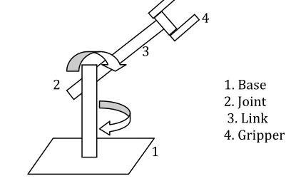
Manipulator is a fancy name for a robot or mechanical arm; hence it will be used intermittently with robot arm. A manipulator is an assembly of segments and joints that can be conveniently divided into three sections: the arm, consisting of one or more segments and joints; the wrist, usually consisting of one to three segments and joints; and a gripper or other means of attaching or grasping. Alternatively, the manipulator can be divided into only two sections, arm and gripper, but for clarity the wrist is separated out as its own section because it performs a unique function. Industrial robots are stationary manipulators whose base is permanently attached to the floor, a table, or a stand. In most cases, however, industrial manipulators are too big and use a geometry that is not effective on a mobile robot, or lack enough sensors (indeed many have no environmental sensors at all) to be considered for use on a mobile robot. Figure 1 shows the basic robotic arm.
4
3
2
1. Base
2. Joint 3. Link
[image:1.612.322.526.572.699.2]4. Gripper 1
Fig- 1: Basic robot arm
WIRELESS CONTROL OF ROBOTIC ARM SYSTEM USING ACCELOREMETER
SENSING AND ZIGBEE APPROACH
Aniket D. Kulkarni
1, Dr. Sayyad Ajij D.
21
Student of M.E.(Embedded System),MIT, Aurangabad, (MH), India
2Professor, Marathwada Institute of Technology, Aurangabad, (MH), India
Dr.
© 2016, IRJET | Impact Factor value: 4.45 | ISO 9001:2008 Certified Journal | Page 396
3. SYSTEM MODELING
The generalized block diagram of project is shown in figure 3.1. The block diagram can be divided into two parts first one is transmitter and second is receiver.
Fig- 2: Transmitter
Fig- 3: Receiver
In this dissertation there would be two section transmitter and receiver. The receiver part would contain the servo motor. The servo motor would be connected to ATmega328 microcontroller. This ATmega328 would be connected to the PC through serial port. The transmitter part would be connected to the MEMS sensor. The output of sensor is the analog voltage. This analog output would be converted into digital using ADC which is inbuilt in the LPC2138 microcontroller.
The output of ADC is processed and further given to The Zigbee module. This Zigbee module will send the data to PC and further it is received by the Zigbee Module connected to the receiver part. Depending upon the X, Y or Z movement of the sensor the respective ARM for the X, Y or Z will move. The Crystal will be used for clock frequency
Generation. The RC network circuit will be used to generate the power on reset for the microcontroller.
4. IMPLEMENTATION AND ANALYSIS
The accelerometers are connected to the LPC2138 development board which is then connected to the Computer via wireless communication. Now the data received by the computer is processed to remove as much noise as possible. Again the Aurdino development board is connected with the computer through wired communication channel. Figure 3 shows the physical setup of the system. Each motor moves the arm in one plane. As we have implemented two motors at the shoulder joint as can be seen from Figure 3, M1 is to move the arm in Y-Z plane and motor M2 is for the movement along the X-Z plane. In this way the two motors provide the shoulder joint to be moved in any direction in space.
Fig-4: Typical set up of the system
Fig-5: Prototype of robotic arm
Accelerometer Sensors
Microcontroller
Zigbee Trans-receiver Power Supply
Zigbee Trans-receiver
Computer with MATLAB
Microcontroller ROBOT
With Servo motor
Power supply
Motor M2
© 2016, IRJET | Impact Factor value: 4.45 | ISO 9001:2008 Certified Journal | Page 397
The calculation of torque is depending on the link length of the robotic arm and the weight of an object. Torque is defined as turning or twisting force and is calculated using the following relation:
Torque = Force × Length = F× L
Force (F) = m × g Torque = m × g × L
Speed of the motor depends on the model of the servo motor. The more power used will be able to lift an item quickly. Different model of servo motor has different torque and the ability to lift heavy weight is depending on it. Result from the torque calculation will help on choosing suitable servo motor to lift an item within specific weight.
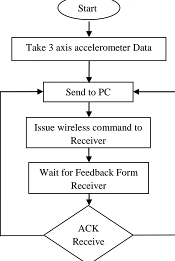
4.1 Hand motion detection
The hand motion is recorded by accelerometer sensor. The signal conditioning circuit amplifies and converts it into three axis representation in digital format. The respective command developed by LPC2138 is send to remote PC through zigbee transmitter. The output buffer is computer memory allocated by the serial port object to store data that is to be written to the device. A flow chart is shown in figure6.
Fig-6: flow chart of hand motion detection
4.2Data Acquisition, Processing and Calibration
Data acquisition (DAQ) is the process of measuring an electrical or physical phenomenon such as voltage, current, temperature, pressure, or sound with a computer. A DAQ system consists of sensors, DAQ measurement hardware, and a computer with programmable software.4.3Data Acquisition
The data from the accelerometer is shown in Figure 4 which is plotted using MATLAB. LPC2138 sends the output of the accelerometer after A-D conversion through the serial port. Figure show the real time plots of the serial data. Further processing will be carried out at a later stage of our project.
Fig-7: Accelerometer data in time domain
4.4 Data processing
Here in my project I have plot FFT & use a simple moving average algorithm to smoothen the output of the accelerometer. Using the Fourier series representation we have Discrete Fourier Transform (DFT) for finite length signal. DFT can convert time‐domain discrete signal into frequency‐ domain discrete spectrum. The Fast Fourier Transform does not refer to a new or different type of Fourier transform. It refers to a very efficient algorithm for computing the DFT. The time taken to evaluate a DFT on a computer depends principally on the number of multiplications involved. DFT needs N2 multiplications. FFT only needs Nlog2 (N).
ACK Receive
Take 3 axis accelerometer Data
Start
Send to PC
Issue wireless command to Receiver
[image:3.612.319.547.300.494.2] [image:3.612.73.248.418.679.2]© 2016, IRJET | Impact Factor value: 4.45 | ISO 9001:2008 Certified Journal | Page 398
The MATLAB fft function returns the DFT y of an input vector x using a fast Fourier transform algorithm:
y = fft (x);
In this call to fft, the window length m = length(x) and the transform length n = length(y) are the same. The transform length is specified by an optional second argument:
y = fft (x,n);
Fig- 8 : FFT graph of accelerometer signal
4.5 System integration and testing
The robot arm design project was split into smaller tasks to reduce complexity and also to facilitate parallel implementation of independent tasks. The tasks include robot arm fabrication, assembly, control circuit design and implementation, design and implementation of wireless communication module and software development for both the GUI and microcontrollers. These tasks constantly met to establish and update guidelines that will ensure the compatibility of the various modules during system integration.
With respect to hand motion in particular direction the motion of robotic arm shown in figure 9, 10, 11 and12 given below.
Fig-9: Movement of robotic arm in upward direction
Fig-10: Movement of robotic arm in downward direction
Fig-11: Movement of robotic arm in right direction
Fig-12 : Movement of robotic arm in left direction
5. RESULTS
A) Speed of execution
© 2016, IRJET | Impact Factor value: 4.45 | ISO 9001:2008 Certified Journal | Page 399
time of AD conversion should be significantly less than the response time. Since the bandwidth of ADXL335 is 1600 Hz, to acquire accurate reading we cannot measure at a rate more than that. Moreover, the electrical response time is 2ms, so we chose a time of 10ms for each AD conversion. The total time of updating one gesture is <70 ms.Typical hand movement value is (~10Hz). Based on our experience, we conclude that the controller is sensitive and respond rapidly to hand action.
B) Accuracy
I have separated and tested the accuracy of detecting hand movement, hand direction and the overall action. For each test, we made sure the actions were in every direction. Based on result, I conclude that the accuracy was very high for static gestures such as hand gestures. The accuracy for dynamic movement is low due to noise.
C) Safety Considerations
I enforced safety in several ways. I use insulating tape to completely wrap the metal contacts to make sure no short circuit occurs. Consequently, the only parts that the user will touch are the device itself, the USB port and the power plug, which are all secure. In addition, we make sure the project doesn’t contain any sharp object or small components, and is thus safe.
D)Usability
The idea of this dissertation is simple, but as explained before, there exists a tradeoff between the expandability of the action library and usability. I took the approach of predefining all basic movements and most common actions that are suitable for robotic arm inputs, while leaving user the freedom to expand the gestures that could be recognized. Using the control mapping manager is very easy, and once the manager is set up, the device can operate just like simulating keyboard.
6. CONCLUSION
The objectives of this project has been achieved which was developing the hardware and software for an accelerometer controlled robotic arm. Observation clearly shows that its movement is precise, accurate, and is easy to control and user friendly to use. The robotic arm has been developed successfully as the movement of the robot
can be controlled precisely. By introducing the concept of wireless technology, It is possible to make our communication more efficient and faster. When compared with other common input devices, especially the teach pendant, this approach using accelerometers is more intuitive and easy to work, besides offering the possibility to control a robot by wireless means. Using this system, a non expert robot programmer can control a robot quickly and in a natural way. The low price and short set-up time are other advantages of the system.
REFERENCES
[1]Rudiger Dillmann “Teaching and learning of robot tasks via observation of human performance,” Elsevier International journal, Volume 3, Iss: 2, pp.10-14, April 2004
[2] Jin-Shyan Lee, Yu-Wei Su, and Chung-Chou Shen “A Comparative Study of Wireless Protocols: Bluetooth, UWB, ZigBee, and Wi-Fi” International Conference on IEEE Industrial Electronics Society, Nov. 5-8, 2007.
[3] Alessandro De Luca , Dierk Schroder, Michael Thummel, “An Acceleration-based State Observer for Robot Manipulators with Elastic Joints” IEEE International Conference on Robotics and Automation , Volume 3, Iss: 2, pp.10-14 ,April 2007.
[4] Jegede Olawale, Awodele Oludele, Ajayi Ayodele, and Ndong Miko Alejandro “Development of a Microcontroller Based Robotic Arm” Computer Science and IT Education Conference, Volume 2, Iss: 2, pp.5, 2007.
[5] Claus Lenz, Suraj Nair, Markus Rickert, Alois Knoll “Joint-Action for Humans and Industrial Robots for Assembly Tasks”IEEE International Symposium on Robot and Human Interactive Communication, August 1-3, 2008. [6] Emanuele Cattin , Stefano Roccella , Nicola Vitiello , Irene Sardellitti “Design and Development of a Novel Robotic Platform for Neuro-Robotics Applications: the NEURobotics ARM (NEURARM)” International Journal Advanced Robotics, volume 22, pp.3–37,2008.
[7] Jeffrey R Croxell, Jerry B Weinberg, Ryan W Krauss, Scott R Smith “Robotic Limb Calibration: Accelerometer Based Discovery of Kinematic Constants”white paper (https://www.aaai.org/papers/
Workshops/2008).
© 2016, IRJET | Impact Factor value: 4.45 | ISO 9001:2008 Certified Journal | Page 400
gesture and posture recognition,” Industrial Robot: An International Journal, Volume 37, Iss: 2, pp. 137 – 147, 2009.
[9] Jianfeng Liu, Zhigeng Pan, and Xiangcheng Li “An Accelerometer-Based Gesture Recognition Algorithm and its Application for 3D Interaction” International Journal of Computer Science and Information Systems, Vol. 7, No. 1, February 2010.
[10] Ashraf Elfasakhany, Eduardo Yanez, Karen Baylon, Ricardo Salgado“Design and Development of a Competitive Low-Cost Robot Arm with Four Degrees of Freedom” International Journal of scientific research, volume1,PP.47-55,2011.
[12] Ruize Xu, Shengli Zhou, Wen J. Li, Fellow, “MEMS Accelerometer Based Nonspecific-User Hand Gesture Recognition” IEEE Sensors Journal, volume 12, NO. 5, May 2012.
[11] Meenaakumari.M, M.Muthulakshmi “Mems Accelerometer Based Hand Gesture Recognition” International Journal of Advanced Research in Computer Engineering & Technology (IJARCET), Volume 2, No 5, May 2013.
[12] N.Nandhini, SU.Suganthi “Wireless Control of a Robotic Arm Using Inertial Sensor” International Journal of Engineering and Advanced Technology (IJEAT), Volume-2, Issue-4, April 2013.
[13] Puran Singh, Anil Kumar, Mahesh Vashisth “Design of a Robotic Arm with Gripper & End Effector for Spot Welding” Universal Journal of Mechanical Engineering, volume 1(3), PP. 92-97, 2013.